
Aspire E360 User Guide EN
Page 14
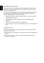
Possible upgrade options include the following: • Replace the HDD with a higher capacity model, or add a second HDD. • Install additional memory. • Install a graphics card as a fax/modem card, in one of the empty PCI slots. Opening The Case Before you purchase them. ...replace components. b) Push the case lock to the right and pull the side panel toward you to the documentation that are compatible with your Aspire computer. English 8 Installing new components Make sure you only use components that comes with your new components before you open the case, turn your...
Possible upgrade options include the following: • Replace the HDD with a higher capacity model, or add a second HDD. • Install additional memory. • Install a graphics card as a fax/modem card, in one of the empty PCI slots. Opening The Case Before you purchase them. ...replace components. b) Push the case lock to the right and pull the side panel toward you to the documentation that are compatible with your Aspire computer. English 8 Installing new components Make sure you only use components that comes with your new components before you open the case, turn your...

Aspire T160/Aspire E360 Service Guide
Page 7
... guide. Please note WHEN ORDERING FRU PARTS, that you with further technical details. 2. VII For ACER-AUTHORIZED SERVICE PROVIDERS, your Acer office may have decided to order FRU parts for repair and service of a machine (e.g. To better... fit local market requirements and enhance product competitiveness, your regional Acer office to extend the functionality of customer machines. Preface Before using this printed Service Guide. In such cases,...most up-to-date information available on card, modem, or extra memory capability).
... guide. Please note WHEN ORDERING FRU PARTS, that you with further technical details. 2. VII For ACER-AUTHORIZED SERVICE PROVIDERS, your Acer office may have decided to order FRU parts for repair and service of a machine (e.g. To better... fit local market requirements and enhance product competitiveness, your regional Acer office to extend the functionality of customer machines. Preface Before using this printed Service Guide. In such cases,...most up-to-date information available on card, modem, or extra memory capability).
Aspire T160/Aspire E360 Service Guide
Page 8
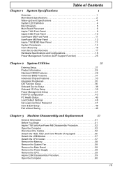
... System LED Definition 4 Block Diagram 5 Main Board Placement 6 Aspire T160 Front Panel 9 Aspire E360 Front Panel 10 AcerPower M6 Front Panel 11 AcerPower M6 Rear Panel 12 Aspire T160/E360 Rear Panel 13 System Peripherals 14 Acer eRecovery 15 Acer disc-to-disc Recovery 17 Hardware Specifications and Configurations 18 Power ...Reader (if equipped 55 Detach the USB Module 57 Detach the CPU Cooler 57 Remove the Memory 58 Remove the System Fan 58 Remove the Main Board 58 Remove the Power Supply 59 Remove the CPU 59 Aspire E360 Desassembly Procedure 59 Open the Computer 60 VIII
... System LED Definition 4 Block Diagram 5 Main Board Placement 6 Aspire T160 Front Panel 9 Aspire E360 Front Panel 10 AcerPower M6 Front Panel 11 AcerPower M6 Rear Panel 12 Aspire T160/E360 Rear Panel 13 System Peripherals 14 Acer eRecovery 15 Acer disc-to-disc Recovery 17 Hardware Specifications and Configurations 18 Power ...Reader (if equipped 55 Detach the USB Module 57 Detach the CPU Cooler 57 Remove the Memory 58 Remove the System Fan 58 Remove the Main Board 58 Remove the Power Supply 59 Remove the CPU 59 Aspire E360 Desassembly Procedure 59 Open the Computer 60 VIII
Aspire T160/Aspire E360 Service Guide
Page 9
Table of Contents Remove the PCI 60 Detach the CPU Cooler 61 Remove the Memory 62 Disconnect the Cables 62 Disassemble the HDD, ODD, FDD and Card Reader 65 Disassemble the USB Module 67 Remove the System Fan 67 Remove ... 97 INTR (Intruder, Case Open Header 97 BAT (Battery 98 How to Erase CMOS 98 Chapter 6 FRU (Field Replaceable Unit) List 99 General Description 99 Aspire E360 Exploded Diagram 100 AcerPower M6 Exploded Diagram 101 Parts 102 IX
Table of Contents Remove the PCI 60 Detach the CPU Cooler 61 Remove the Memory 62 Disconnect the Cables 62 Disassemble the HDD, ODD, FDD and Card Reader 65 Disassemble the USB Module 67 Remove the System Fan 67 Remove ... 97 INTR (Intruder, Case Open Header 97 BAT (Battery 98 How to Erase CMOS 98 Chapter 6 FRU (Field Replaceable Unit) List 99 General Description 99 Aspire E360 Exploded Diagram 100 AcerPower M6 Exploded Diagram 101 Parts 102 IX
Aspire T160/Aspire E360 Service Guide
Page 10
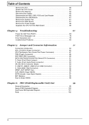
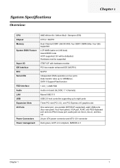
System Specifications Overview Chapter 1 CPU Chipset Memory System BIOS Feature Super I/O IDE Interface RTC Serial ATA FDD Interface Audio LAN USB Expansion Slots I/O Ports Power Connectors Power management AMD Athlon 64 / Athlon ...
System Specifications Overview Chapter 1 CPU Chipset Memory System BIOS Feature Super I/O IDE Interface RTC Serial ATA FDD Interface Audio LAN USB Expansion Slots I/O Ports Power Connectors Power management AMD Athlon 64 / Athlon ...
Aspire T160/Aspire E360 Service Guide
Page 11
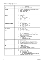
Default is enabled. Main Board Specifications Size Processor System Chipset Memory PCI Express / PCI Slots FDD Interface IDE Interface Audio LAN USB (AcerPower M6) Description T Max. 244 mm x 244 mm, Micro ATX T Processor type: AMD Athlon ...64 / Athlon 64x2 / Sempron T Socket type: AMD Socket 939 T Socket quantity: one T North bridge: Nvidia C51G T South bridge: MCP51 T Memory type: T DDR T CAS latency, CL = 4 T Socket type: DDR memory slots T Socket quantity: four T Capacity: 256MB to 4GB T Single channel T PCI Express Slot type: x1 / x16 T Quantity: none / one T PCI Slot...
Default is enabled. Main Board Specifications Size Processor System Chipset Memory PCI Express / PCI Slots FDD Interface IDE Interface Audio LAN USB (AcerPower M6) Description T Max. 244 mm x 244 mm, Micro ATX T Processor type: AMD Athlon ...64 / Athlon 64x2 / Sempron T Socket type: AMD Socket 939 T Socket quantity: one T North bridge: Nvidia C51G T South bridge: MCP51 T Memory type: T DDR T CAS latency, CL = 4 T Socket type: DDR memory slots T Socket quantity: four T Capacity: 256MB to 4GB T Single channel T PCI Express Slot type: x1 / x16 T Quantity: none / one T PCI Slot...
Aspire T160/Aspire E360 Service Guide
Page 12
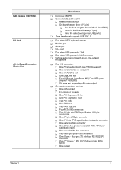
USB (Aspire E360/T160) I/O Ports All On-Board Connector / Device List Description T Controller: MCP51 T Connectors Quantity: eight T Rear connectors: four T On-board header: three (2*5 pin) T One for front ... serial port T One VGA (CRT) port T One GigaLAN port T Four USB ports (AcerPower M6) / Two USB ports (Aspire T160/E360) T Six ports jack supporting HD audio output T On-board connectors / devices T One CPU socket T Four memory sockets T One PCI Express x16 slot T One PCI Express x1 slot T Two PCI slots T One FDD slot...
USB (Aspire E360/T160) I/O Ports All On-Board Connector / Device List Description T Controller: MCP51 T Connectors Quantity: eight T Rear connectors: four T On-board header: three (2*5 pin) T One for front ... serial port T One VGA (CRT) port T One GigaLAN port T Four USB ports (AcerPower M6) / Two USB ports (Aspire T160/E360) T Six ports jack supporting HD audio output T On-board connectors / devices T One CPU socket T Four memory sockets T One PCI Express x16 slot T One PCI Express x1 slot T Two PCI slots T One FDD slot...

Aspire T160/Aspire E360 Service Guide
Page 27
Hardware Specifications and Configurations Major Chips Item System Core Logic Super I/O Controller LAN Controller Memory Controller IDE Controller Audio Controller VGA Controller Keyboard Controller Nvidia C51G MCP51 ITE 8712F Marvell 88E1111 Nvidia C51G MCP51 ALC850 Nvidia C51G ITE 8712F Specification ...
Hardware Specifications and Configurations Major Chips Item System Core Logic Super I/O Controller LAN Controller Memory Controller IDE Controller Audio Controller VGA Controller Keyboard Controller Nvidia C51G MCP51 ITE 8712F Marvell 88E1111 Nvidia C51G MCP51 ALC850 Nvidia C51G ITE 8712F Specification ...

Aspire T160/Aspire E360 Service Guide
Page 28
...First-Level Cache Configurations Cache function control Enable/Disable by BIOS Setup Chapter 1 19 System Memory Item Memory Slot Number Memory Size per Slot Supported Maximum Memory Size Supported Memory Speed Supported memory voltage Support memory module package Support to parity check feature Support to system installed with a Pentium 4 ... Setup Second-Level Cache Configurations The information below is only applicable to Error Correction Code (ECC) feature Memory module combinations four slots 256 MB ~ 1GB 4GB 400 MHz 1.8 V 240-pin DIMM Yes Yes Specification You can install...
...First-Level Cache Configurations Cache function control Enable/Disable by BIOS Setup Chapter 1 19 System Memory Item Memory Slot Number Memory Size per Slot Supported Maximum Memory Size Supported Memory Speed Supported memory voltage Support memory module package Support to parity check feature Support to system installed with a Pentium 4 ... Setup Second-Level Cache Configurations The information below is only applicable to Error Correction Code (ECC) feature Memory module combinations four slots 256 MB ~ 1GB 4GB 400 MHz 1.8 V 240-pin DIMM Yes Yes Specification You can install...
Aspire T160/Aspire E360 Service Guide
Page 38
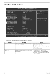
... [None] IDE Channel 4 Master [None] IDE Channel 5 Master [None] Floppy Drive A [None] Video Setting Halt On Setting [EGA/VGA] [All, But Keyboard] Base Memory Setting 640K Extended Memory Setting 456704K :Move Enter:Select +/-/PU/PD:Value F10:Save ESC:Exit F1:General Help F5 Previous Values F7:Optimized Defaults The following table...
... [None] IDE Channel 4 Master [None] IDE Channel 5 Master [None] Floppy Drive A [None] Video Setting Halt On Setting [EGA/VGA] [All, But Keyboard] Base Memory Setting 640K Extended Memory Setting 456704K :Move Enter:Select +/-/PU/PD:Value F10:Save ESC:Exit F1:General Help F5 Previous Values F7:Optimized Defaults The following table...

Aspire T160/Aspire E360 Service Guide
Page 39
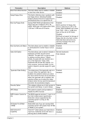
... detection step and allow for automatic device detection. Parameter IDE Primary/Secondary Master, Slave Drive A Video Setting Halt On Base Memory Setting Extended Memory Setting Description Options Allows you . Chapter 2 30 The IDE CD-ROM is present during POST (default) None: Select this...Landing Zone: Landing Zone T Sector: Number of sectors The category identifies the types of CPU. The BIOS determines how much extended memory is always automatically detected. The option EGA/VGA means Enhanced Graphic Adapter/Video Graphic Array. This item enables user to select the ...
... detection step and allow for automatic device detection. Parameter IDE Primary/Secondary Master, Slave Drive A Video Setting Halt On Base Memory Setting Extended Memory Setting Description Options Allows you . Chapter 2 30 The IDE CD-ROM is present during POST (default) None: Select this...Landing Zone: Landing Zone T Sector: Number of sectors The category identifies the types of CPU. The BIOS determines how much extended memory is always automatically detected. The option EGA/VGA means Enhanced Graphic Adapter/Video Graphic Array. This item enables user to select the ...
Aspire T160/Aspire E360 Service Guide
Page 41
... select if chipset or keyboard controller should control GateA20. Note that there will not be used to provide support for the system chipset to address memory above 1 Mbyte. Boot Up NumLock Status This item allows user to enable or disable Enabled to set up enable or disable the APCI function Enabled...
... select if chipset or keyboard controller should control GateA20. Note that there will not be used to provide support for the system chipset to address memory above 1 Mbyte. Boot Up NumLock Status This item allows user to enable or disable Enabled to set up enable or disable the APCI function Enabled...
Aspire T160/Aspire E360 Service Guide
Page 42
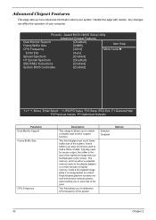
... used to hold a frame of data. This field displays how much frame buffer size of the system. Handle this page with several memory planes, each holding one or more advanced information about your computer. Enabled Disabled Options 33 Chapter 2 Award BIOS CMOS Setup Utility Advanced ...support function. This field allows you to determine CPU frequency of the system. Phoenix - The memory, which is either a separate memory bank on the display adapter or a reserved part of regular memory, holds a bit mapped image while it is the size of the maximum image that can ...
... used to hold a frame of data. This field displays how much frame buffer size of the system. Handle this page with several memory planes, each holding one or more advanced information about your computer. Enabled Disabled Options 33 Chapter 2 Award BIOS CMOS Setup Utility Advanced ...support function. This field allows you to determine CPU frequency of the system. Phoenix - The memory, which is either a separate memory bank on the display adapter or a reserved part of regular memory, holds a bit mapped image while it is the size of the maximum image that can ...
Aspire T160/Aspire E360 Service Guide
Page 43
... sets. This benefit may result. and SSE2-optimized software to make use of those instructions to process large amounts of memory controller. Selecting Enabled allows caching of the system BIOS ROM at the default setting of LDI & PCI bus control. This... multiple data elements simultaneously. It is Hyper Transport between CPU and North Bridge. HT is highly recommended that you leave this memory area, a system error may in some parameters of data simultaneously. Enabled Disabled Options Enabled Disabled Enabled Disabled Enabled Disabled Enabled ...
... sets. This benefit may result. and SSE2-optimized software to make use of those instructions to process large amounts of memory controller. Selecting Enabled allows caching of the system BIOS ROM at the default setting of LDI & PCI bus control. This... multiple data elements simultaneously. It is Hyper Transport between CPU and North Bridge. HT is highly recommended that you leave this memory area, a system error may in some parameters of data simultaneously. Enabled Disabled Options Enabled Disabled Enabled Disabled Enabled Disabled Enabled ...

Aspire T160/Aspire E360 Service Guide
Page 47
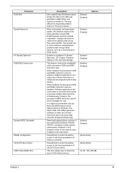
...[Disabled] :Move Enter:Select +/-/PU/PD:Value F10:Save ESC:Exit F1:General Help F5:Previous Values F7:Optimized Defaults Parameter OnChip USB USB Memory Type USB Keyboard Support USB Mouse Support AC 97 Audio MAC Lan MAC Lan Boot ROM Description Options This field allows you should certainly enable... this BIOS feature. You can disable this item to change the type of USB Memory to use . Enabled Disabled This field enables or disables USB mouse support function. This may free up an IRQ for other devices to ...
...[Disabled] :Move Enter:Select +/-/PU/PD:Value F10:Save ESC:Exit F1:General Help F5:Previous Values F7:Optimized Defaults Parameter OnChip USB USB Memory Type USB Keyboard Support USB Mouse Support AC 97 Audio MAC Lan MAC Lan Boot ROM Description Options This field allows you should certainly enable... this BIOS feature. You can disable this item to change the type of USB Memory to use . Enabled Disabled This field enables or disables USB mouse support function. This may free up an IRQ for other devices to ...

Aspire T160/Aspire E360 Service Guide
Page 50
S1(POS): The S1 sleep mode is saved to main memory. S1 (POS): Set ACPI suspend type to essential components such as main memory and wake-capable devices and all system context. Max Saving: Maximum power savings. User Define: Set each mode individually. Saving: Minimum power savings. S3 ... your own style of computer use. The information stored in a manner consistent with your system to most effectively save energy while operating in memory will be used to restore the PC to enable or disable the ACPI function Enabled Disabled This item specifies the power saving modes for ACPI...
S1(POS): The S1 sleep mode is saved to main memory. S1 (POS): Set ACPI suspend type to essential components such as main memory and wake-capable devices and all system context. Max Saving: Maximum power savings. User Define: Set each mode individually. Saving: Minimum power savings. S3 ... your own style of computer use. The information stored in a manner consistent with your system to most effectively save energy while operating in memory will be used to restore the PC to enable or disable the ACPI function Enabled Disabled This item specifies the power saving modes for ACPI...
Aspire T160/Aspire E360 Service Guide
Page 56
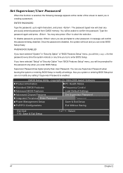
Set Supervisor/User Password When this function is selected, the following message appears at "Security Option" from CMOS memory. Also you can enter BIOS Setup freely. You may also press to eight characters, and press . A message will boot and you system or entering BIOS ...
Set Supervisor/User Password When this function is selected, the following message appears at "Security Option" from CMOS memory. Also you can enter BIOS Setup freely. You may also press to eight characters, and press . A message will boot and you system or entering BIOS ...
Aspire T160/Aspire E360 Service Guide
Page 67
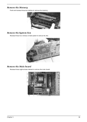
Remove the Main board Release those four screws on back panel to remove the fan. Chapter 3 58 Remove the System Fan Release those eight screws marked to remove the memory. Remove the Memory Push and release those two latches to remove the main board.
Remove the Main board Release those four screws on back panel to remove the fan. Chapter 3 58 Remove the System Fan Release those eight screws marked to remove the memory. Remove the Memory Push and release those two latches to remove the main board.

Aspire T160/Aspire E360 Service Guide
Page 71
Disconnect the Cables 1. Disconnect the Audio cable and CD_IN cable. 2. Release the CPU Cooler latch then remove it. Chapter 3 62 Remove the Memory Press those latches on the left and right sides to pop up the four memories.
Disconnect the Cables 1. Disconnect the Audio cable and CD_IN cable. 2. Release the CPU Cooler latch then remove it. Chapter 3 62 Remove the Memory Press those latches on the left and right sides to pop up the four memories.

Aspire T160/Aspire E360 Service Guide
Page 79
... check points to E000 & F000 shadow RAM. T Auto-detection of L2 cache (socket 7 or below ) T Program basic chipset registers Detect memory T Auto-detection of the power-on password option. The Power-On Self Test (POST) is fatal. This latch can be latched at port ...system components, and controls the operation of DRAM size, type and ECC. Several items are not listed in numeric co-processor and cache memory subsystem T Direct Memory Access (DMA) controller T Interrupt system T Three programmable timers T ROM subsystem T RAM subsystem T CMOS RAM subsystem and real time ...
... check points to E000 & F000 shadow RAM. T Auto-detection of L2 cache (socket 7 or below ) T Program basic chipset registers Detect memory T Auto-detection of the power-on password option. The Power-On Self Test (POST) is fatal. This latch can be latched at port ...system components, and controls the operation of DRAM size, type and ECC. Several items are not listed in numeric co-processor and cache memory subsystem T Direct Memory Access (DMA) controller T Interrupt system T Three programmable timers T ROM subsystem T RAM subsystem T CMOS RAM subsystem and real time ...


