
Aspire E360 User Guide EN
Page 14
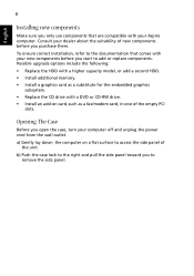
... sure you only use components that comes with your new components before you purchase them. Opening The Case Before you start to remove the side panel. a) Gently lay down the computer on card, such as a fax/modem card, in one of the unit. Possible upgrade options include the following: • ...with a DVD or CD-RW drive. • Install an add-on a flat surface to access the side panel of the empty PCI slots. b) Push the case lock to the right and pull the side panel toward you to add or replace components. Consult your dealer about the suitability of new components before...
... sure you only use components that comes with your new components before you purchase them. Opening The Case Before you start to remove the side panel. a) Gently lay down the computer on card, such as a fax/modem card, in one of the unit. Possible upgrade options include the following: • ...with a DVD or CD-RW drive. • Install an add-on a flat surface to access the side panel of the empty PCI slots. b) Push the case lock to the right and pull the side panel toward you to add or replace components. Consult your dealer about the suitability of new components before...

Aspire E360 User Guide EN
Page 15
... your system to restart your computer. Just press any of the following : • Is a non-bootable (non-system) diskette in and turned on the rear panel of your computer and each is set to restart your system, refers to save power. If pressing a key does not work, you plugged the power...
... your system to restart your computer. Just press any of the following : • Is a non-bootable (non-system) diskette in and turned on the rear panel of your computer and each is set to restart your system, refers to save power. If pressing a key does not work, you plugged the power...
Aspire T160/Aspire E360 Service Guide
Page 8
... Specifications 2 Wake-up Event Specifications 4 System LED Definition 4 Block Diagram 5 Main Board Placement 6 Aspire T160 Front Panel 9 Aspire E360 Front Panel 10 AcerPower M6 Front Panel 11 AcerPower M6 Rear Panel 12 Aspire T160/E360 Rear Panel 13 System Peripherals 14 Acer eRecovery 15 Acer disc-to-disc Recovery 17 Hardware Specifications and Configurations 18 Power Management Function (ACPI Support... the Memory 58 Remove the System Fan 58 Remove the Main Board 58 Remove the Power Supply 59 Remove the CPU 59 Aspire E360 Desassembly Procedure 59 Open the Computer 60 VIII
... Specifications 2 Wake-up Event Specifications 4 System LED Definition 4 Block Diagram 5 Main Board Placement 6 Aspire T160 Front Panel 9 Aspire E360 Front Panel 10 AcerPower M6 Front Panel 11 AcerPower M6 Rear Panel 12 Aspire T160/E360 Rear Panel 13 System Peripherals 14 Acer eRecovery 15 Acer disc-to-disc Recovery 17 Hardware Specifications and Configurations 18 Power Management Function (ACPI Support... the Memory 58 Remove the System Fan 58 Remove the Main Board 58 Remove the Power Supply 59 Remove the CPU 59 Aspire E360 Desassembly Procedure 59 Open the Computer 60 VIII
Aspire T160/Aspire E360 Service Guide
Page 9
... Fan Power Conncetor 87 FDD (Floppy Connector 88 IDE1/IDE2 (IDE Connector 89 SATA1/SATA2/SATA3/SATA4 (Serial ATA Connector 91 F_Panel (Front Panel Jumper 92 F_Audio (Front Audio Panel connector 93 CD_IN (CD In Connector, Black 94 F_USB1/F_USB2/F_USB3 (Front USB Connector 94 F_1394 (IEEE 1394 Connector 95 SPDIF_OUT (SPDIF... 97 INTR (Intruder, Case Open Header 97 BAT (Battery 98 How to Erase CMOS 98 Chapter 6 FRU (Field Replaceable Unit) List 99 General Description 99 Aspire E360 Exploded Diagram 100 AcerPower M6 Exploded Diagram 101 Parts 102 IX
... Fan Power Conncetor 87 FDD (Floppy Connector 88 IDE1/IDE2 (IDE Connector 89 SATA1/SATA2/SATA3/SATA4 (Serial ATA Connector 91 F_Panel (Front Panel Jumper 92 F_Audio (Front Audio Panel connector 93 CD_IN (CD In Connector, Black 94 F_USB1/F_USB2/F_USB3 (Front USB Connector 94 F_1394 (IEEE 1394 Connector 95 SPDIF_OUT (SPDIF... 97 INTR (Intruder, Case Open Header 97 BAT (Battery 98 How to Erase CMOS 98 Chapter 6 FRU (Field Replaceable Unit) List 99 General Description 99 Aspire E360 Exploded Diagram 100 AcerPower M6 Exploded Diagram 101 Parts 102 IX
Aspire T160/Aspire E360 Service Guide
Page 10
... ports Three PCI slot (PCI 2.3), one PCI Express x16 graphics slot One serial port, one parallel (EPP/ECP supported), eight USB ports (four rear panel / four front panel), VGA port, RJ45, one PS/2 keyboard port and one PS/2 mouse port, audio jack six mic-in, line-in, and lineout 24-pin ATX...
... ports Three PCI slot (PCI 2.3), one PCI Express x16 graphics slot One serial port, one parallel (EPP/ECP supported), eight USB ports (four rear panel / four front panel), VGA port, RJ45, one PS/2 keyboard port and one PS/2 mouse port, audio jack six mic-in, line-in, and lineout 24-pin ATX...

Aspire T160/Aspire E360 Service Guide
Page 16
... BZ1 Buzzer 22 SPEAKER Speaker cable connector 23 F_1394 Front 1394 header 24 F_USB1 Front USB header 25 F_USB2 Front USB header 26 FP Front panel 27 TBL_EN Boot block jumper 28 CLR_CMOS Clear CMOS (password switch) 29 INTR Intruder 30 J2 Recovery Chapter 1 7 No.
... BZ1 Buzzer 22 SPEAKER Speaker cable connector 23 F_1394 Front 1394 header 24 F_USB1 Front USB header 25 F_USB2 Front USB header 26 FP Front panel 27 TBL_EN Boot block jumper 28 CLR_CMOS Clear CMOS (password switch) 29 INTR Intruder 30 J2 Recovery Chapter 1 7 No.
Aspire T160/Aspire E360 Service Guide
Page 19
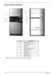
Description 1 Optical driver 2 Optical drive eject button 3 Power button 4 USB ports 5 Speaker/Headphone jack 6 Microphone jack 7 Indicators 8 Floppy disk drive 9 Card reader 10 IEEE 1394 port NOTE: The picture left is the front bezel with cover slided down. 10 Chapter 1 Aspire E360 Front Panel No.
Description 1 Optical driver 2 Optical drive eject button 3 Power button 4 USB ports 5 Speaker/Headphone jack 6 Microphone jack 7 Indicators 8 Floppy disk drive 9 Card reader 10 IEEE 1394 port NOTE: The picture left is the front bezel with cover slided down. 10 Chapter 1 Aspire E360 Front Panel No.
Aspire T160/Aspire E360 Service Guide
Page 21
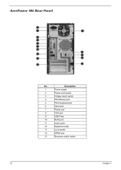
AcerPower M6 Rear Panel No. Description 1 Power supply 2 Power cord socket 3 Voltage select switch 4 PS/2 Mouse port 5 PS/2 Keyboard port 6 Serial port 7 Printer port 8 VGA port 9 USB Ports 10 RJ45 port 11 Audio jacks 12 Expansion slots 13 Lock handle 14 SPDIF port 15 Recovery switch holder 12 Chapter 1
AcerPower M6 Rear Panel No. Description 1 Power supply 2 Power cord socket 3 Voltage select switch 4 PS/2 Mouse port 5 PS/2 Keyboard port 6 Serial port 7 Printer port 8 VGA port 9 USB Ports 10 RJ45 port 11 Audio jacks 12 Expansion slots 13 Lock handle 14 SPDIF port 15 Recovery switch holder 12 Chapter 1
Aspire T160/Aspire E360 Service Guide
Page 23
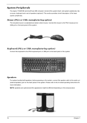
... cable to the included operating instructions for more information. NOTE: speakers are optional and the appearance might be different depending on the back panel of the system. Mouse (PS/2 or USB, manufacturing option) The included mouse is a standard two-button wheel mouse. Please refer to... the audio out (external speaker) port on the actual product. 14 Chapter 1 System Peripherals The Aspire T160/E360 and AcerPower M6 computer consist of the system itself, and system peripherals, like a mouse, keyboard and a set of the basic system peripherals....
... cable to the included operating instructions for more information. NOTE: speakers are optional and the appearance might be different depending on the back panel of the system. Mouse (PS/2 or USB, manufacturing option) The included mouse is a standard two-button wheel mouse. Please refer to... the audio out (external speaker) port on the actual product. 14 Chapter 1 System Peripherals The Aspire T160/E360 and AcerPower M6 computer consist of the system itself, and system peripherals, like a mouse, keyboard and a set of the basic system peripherals....
Aspire T160/Aspire E360 Service Guide
Page 29
... port controller resident bus Number of serial port Serial port location 16550 UART support Connector type Specification ITE 8712F LPC Bus V1.0 / 33MHz One Rear Panel Yes 9-pin D-type female connector USB Port Item Universal HCI Controller Number of the connectors Location USB Class Specification USB 2.0/1.1 MCP51 eight Rear: four for...
... port controller resident bus Number of serial port Serial port location 16550 UART support Connector type Specification ITE 8712F LPC Bus V1.0 / 33MHz One Rear Panel Yes 9-pin D-type female connector USB Port Item Universal HCI Controller Number of the connectors Location USB Class Specification USB 2.0/1.1 MCP51 eight Rear: four for...
Aspire T160/Aspire E360 Service Guide
Page 34
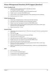
... step=10 minute). T S0, S1, S3 and S5 sleep state support. T Disable H-sync and V-sync signals to control the VESA DPMS monitor. T LED on the panel turns amber colour. T Disable H-sync and V-sync signals to control the VESA DPMS monitor. T On board device power management support. T CPU goes into the Stop...
... step=10 minute). T S0, S1, S3 and S5 sleep state support. T Disable H-sync and V-sync signals to control the VESA DPMS monitor. T LED on the panel turns amber colour. T Disable H-sync and V-sync signals to control the VESA DPMS monitor. T On board device power management support. T CPU goes into the Stop...
Aspire T160/Aspire E360 Service Guide
Page 67
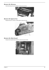
Remove the System Fan Release those four screws on back panel to remove the main board. Remove the Main board Release those two latches to remove the memory. Remove the Memory Push and release those eight screws marked to remove the fan. Chapter 3 58
Remove the System Fan Release those four screws on back panel to remove the main board. Remove the Main board Release those two latches to remove the memory. Remove the Memory Push and release those eight screws marked to remove the fan. Chapter 3 58

Aspire T160/Aspire E360 Service Guide
Page 87
... match its read/write head is clean before diagnosing any system problems. Memory test failed. 1. With the system power on, measure the voltage of Control Panel. 2. Main board. Main board. Main board and Memory NOTE: Ensure the memory modules are installed properly and the contact leads are mismatched. 1. Memory module. 3. Main...
... match its read/write head is clean before diagnosing any system problems. Memory test failed. 1. With the system power on, measure the voltage of Control Panel. 2. Main board. Main board. Main board and Memory NOTE: Ensure the memory modules are installed properly and the contact leads are mismatched. 1. Memory module. 3. Main...
Aspire T160/Aspire E360 Service Guide
Page 101
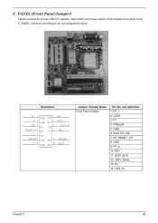
...) Please connect the power LED, PC speaker, reset switch and power switch of the chassis front panel to the F_PANEL connector according to the pin assignment below. and definition 1: FP_1 2: LEDP 3: P1 4: PMSLED 5: GND 6: SWITCH_ON* 7: FP_RESET*_FP 8: GND 9: FP_9 10: KEY 11: ... 9 Black +3.3V_SYS 11 Orange P2 13 Orange Green 2 Green 4 Red 6 Red 8 Green 12 Green 14 LEDP PMSLED SWITCH_ON* GND +3.3V_Dual LED_TX Jumper / Header Name Front Panel Header Pin No.
...) Please connect the power LED, PC speaker, reset switch and power switch of the chassis front panel to the F_PANEL connector according to the pin assignment below. and definition 1: FP_1 2: LEDP 3: P1 4: PMSLED 5: GND 6: SWITCH_ON* 7: FP_RESET*_FP 8: GND 9: FP_9 10: KEY 11: ... 9 Black +3.3V_SYS 11 Orange P2 13 Orange Green 2 Green 4 Red 6 Red 8 Green 12 Green 14 LEDP PMSLED SWITCH_ON* GND +3.3V_Dual LED_TX Jumper / Header Name Front Panel Header Pin No.
Aspire T160/Aspire E360 Service Guide
Page 102
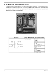
... assignment on the cable is the same as the pin assignment on the main board header. Illustration Jumper / Header Name Pin No. and Definition Front Panel Audio 1: FMIC1 FMIC1 1 FMIC2 3 AUD-FRONT-R 5 NC 7 AUD-FRONT-L 9 2 GND 4 +5V 6 LINE_OUT_R 10 LINE_OUT_L 2: GND 3: FMIC2 4: +5V 5: AUD-FRONT-R 6: ... 9: AUD-FRONT-L 10: LINE_OUT_L 93 Chapter 5 To find out if the chassis you must have front audio connector. F_AUDIO (Front Audio Panel Connector) If you want to utilize the front audio header, your dealer. In order to use Front Audio connector, you are buying support ...
... assignment on the cable is the same as the pin assignment on the main board header. Illustration Jumper / Header Name Pin No. and Definition Front Panel Audio 1: FMIC1 FMIC1 1 FMIC2 3 AUD-FRONT-R 5 NC 7 AUD-FRONT-L 9 2 GND 4 +5V 6 LINE_OUT_R 10 LINE_OUT_L 2: GND 3: FMIC2 4: +5V 5: AUD-FRONT-R 6: ... 9: AUD-FRONT-L 10: LINE_OUT_L 93 Chapter 5 To find out if the chassis you must have front audio connector. F_AUDIO (Front Audio Panel Connector) If you want to utilize the front audio header, your dealer. In order to use Front Audio connector, you are buying support ...
Aspire T160/Aspire E360 Service Guide
Page 109
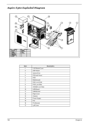
Aspire E360 Exploded Diagram Item 1 2 3 4 5 6 7 8 9 10 11 12 13 14 15 16 17 5.25 Rotate Cover A451 Bezel Optical Drive FDD with Panel HDD Motherboard HDD Lock Slide FDD Lock Slide CDROM Lock Slide USB Board USB Bracket Right Cover Chassis Power Supply Fan PCI Bracket Left Cover Description 100 Chapter 6
Aspire E360 Exploded Diagram Item 1 2 3 4 5 6 7 8 9 10 11 12 13 14 15 16 17 5.25 Rotate Cover A451 Bezel Optical Drive FDD with Panel HDD Motherboard HDD Lock Slide FDD Lock Slide CDROM Lock Slide USB Board USB Bracket Right Cover Chassis Power Supply Fan PCI Bracket Left Cover Description 100 Chapter 6
Aspire T160/Aspire E360 Service Guide
Page 110
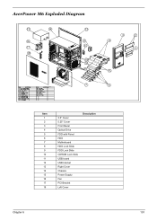
AcerPower M6 Exploded Diagram Item 1 2 3 4 5 6 7 8 9 10 11 12 13 14 15 16 17 18 3.5" Cover 5.25" Cover Front Bezel Optical Drive FDD with Panel HDD Motherboard HDD Lock Slide FDD Lock Slide CDROM Lock Slide USB board USB bracket Right Cover Chassis Power Supply Fan PCI Bracket Left Cover Description Chapter 6 101
AcerPower M6 Exploded Diagram Item 1 2 3 4 5 6 7 8 9 10 11 12 13 14 15 16 17 18 3.5" Cover 5.25" Cover Front Bezel Optical Drive FDD with Panel HDD Motherboard HDD Lock Slide FDD Lock Slide CDROM Lock Slide USB board USB bracket Right Cover Chassis Power Supply Fan PCI Bracket Left Cover Description Chapter 6 101
Aspire T160/Aspire E360 Service Guide
Page 111
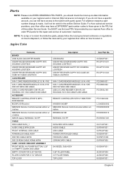
Aspire T160 Partname BOARD USB/ AUDIO DAUGHTER BOARD USB RF RECEIVER BOARD GUPPY W/O HOUSING LOGITECH USB RF ...CABLE USB CABLE POWER SWITCH/LED CABLE FDD DATA CABLE CDROM DATA CABLE S43 BEZEL SUB ASSY 5.25" FILLER PANEL 3.5" FILLER PANEL TOP-LOGO Acer Part No. 55.S26VF.001 RV.GPY01.001 RV.GPY01.002 RV.GPY01.003 PZ.00908.001 PZ.00908... of customers' machines. NOTE: To scrap or to return the defective parts, please follow the rules set by your regional Acer office on your Acer office may have access to the system with guest; KYE 9-IN-1 CARD READER MODULE 3.5 IN. KYE 9-IN-1 CARD ...
Aspire T160 Partname BOARD USB/ AUDIO DAUGHTER BOARD USB RF RECEIVER BOARD GUPPY W/O HOUSING LOGITECH USB RF ...CABLE USB CABLE POWER SWITCH/LED CABLE FDD DATA CABLE CDROM DATA CABLE S43 BEZEL SUB ASSY 5.25" FILLER PANEL 3.5" FILLER PANEL TOP-LOGO Acer Part No. 55.S26VF.001 RV.GPY01.001 RV.GPY01.002 RV.GPY01.003 PZ.00908.001 PZ.00908... of customers' machines. NOTE: To scrap or to return the defective parts, please follow the rules set by your regional Acer office on your Acer office may have access to the system with guest; KYE 9-IN-1 CARD READER MODULE 3.5 IN. KYE 9-IN-1 CARD ...
Aspire T160/Aspire E360 Service Guide
Page 129
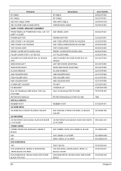
... ASSEMBLY FRONT BEZEL W/ POWER BUTTON, 5.25" 3.5" EMPTY COVER POWER BUTTON ODD COVER 1 W/ HOLDER ODD COVER 2 W/ HOLDER TOP COVER ASSY FRONT COVER WITH ACER LOGO FILLER COVER FOR 3 1/2" DEVICE CHASSIS W/O SIDE DOOR W/O I/O SHIELD H401 SIDE DOOR-LEFT SIDE DOOR-RIGHT S-LOCK-HANDLE ODD HOLDER ASSY FDD HOLDER ASSY...DATA CABLE A451 BEZEL ASSY POWER BUTTON A451 ODD-UPPER DOOR W/ HOLDER A451 ODD-LOWER DOOR W/ HOLDER TOP COVER ASSY FRONT COVER WITH ACER LOGO 3.5" FILLER PANEL H401 CHASSIS W/O SIDE DOOR W/O I/O SHIELD LEFT-BKT-DOOR (PAINTING) RIGHT-BKT-DOOR (PAINTING) S-LOCK-HANDLE ODD HOLDER ASSY FDD ...
... ASSEMBLY FRONT BEZEL W/ POWER BUTTON, 5.25" 3.5" EMPTY COVER POWER BUTTON ODD COVER 1 W/ HOLDER ODD COVER 2 W/ HOLDER TOP COVER ASSY FRONT COVER WITH ACER LOGO FILLER COVER FOR 3 1/2" DEVICE CHASSIS W/O SIDE DOOR W/O I/O SHIELD H401 SIDE DOOR-LEFT SIDE DOOR-RIGHT S-LOCK-HANDLE ODD HOLDER ASSY FDD HOLDER ASSY...DATA CABLE A451 BEZEL ASSY POWER BUTTON A451 ODD-UPPER DOOR W/ HOLDER A451 ODD-LOWER DOOR W/ HOLDER TOP COVER ASSY FRONT COVER WITH ACER LOGO 3.5" FILLER PANEL H401 CHASSIS W/O SIDE DOOR W/O I/O SHIELD LEFT-BKT-DOOR (PAINTING) RIGHT-BKT-DOOR (PAINTING) S-LOCK-HANDLE ODD HOLDER ASSY FDD ...


