Aspire 6530/6530G Quick Guide
Page 7
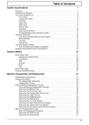
...12 Lock Keys and embedded numeric keypad 12 Windows Keys 13 Hot Keys 14 Special Key 15 Using the System Utilities 16 Acer GridVista (dual-display compatible 16 Hardware Specifications and Configurations 18 System Utilities 27 BIOS Setup Utility 27 Navigating the BIOS Utility ...General Information 42 Pre-disassembly Instructions 42 Disassembly Process 42 External Module Disassembly Process 43 External Modules Disassembly Flowchart 43 Removing the Battery Pack 44 Removing the SD dummy card 45 Removing the ExpressCard dummy card 46 Removing the Lower Covers 47 Removing the DIMM...
...12 Lock Keys and embedded numeric keypad 12 Windows Keys 13 Hot Keys 14 Special Key 15 Using the System Utilities 16 Acer GridVista (dual-display compatible 16 Hardware Specifications and Configurations 18 System Utilities 27 BIOS Setup Utility 27 Navigating the BIOS Utility ...General Information 42 Pre-disassembly Instructions 42 Disassembly Process 42 External Module Disassembly Process 43 External Modules Disassembly Flowchart 43 Removing the Battery Pack 44 Removing the SD dummy card 45 Removing the ExpressCard dummy card 46 Removing the Lower Covers 47 Removing the DIMM...
Aspire 6530/6530G Quick Guide
Page 12
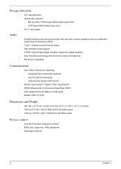
.../43.9 (H) mm (15.71 x 11.49 x 1.61/1.73 inches) • 3.80 kg (8.37 lbs.) with 2 HDDs and 8-cell battery pack • 3.60 kg (7.48 lbs.) with two built-in stereo speakers and one subwoofer* supporting low-frequency effects True5.1-channel surround sound output High...-definition audio support S/PDIF (Sony/Philips Digital Interface) support for digital speakers Acer PureZone technology with 1 HDD and 6-cell battery pack Privacy control • Acer Bio-Protection fingerprint solution* • BIOS user, supervisor, HDD passwords • Kensington lock slot ...
.../43.9 (H) mm (15.71 x 11.49 x 1.61/1.73 inches) • 3.80 kg (8.37 lbs.) with 2 HDDs and 8-cell battery pack • 3.60 kg (7.48 lbs.) with two built-in stereo speakers and one subwoofer* supporting low-frequency effects True5.1-channel surround sound output High...-definition audio support S/PDIF (Sony/Philips Digital Interface) support for digital speakers Acer PureZone technology with 1 HDD and 6-cell battery pack Privacy control • Acer Bio-Protection fingerprint solution* • BIOS user, supervisor, HDD passwords • Kensington lock slot ...

Aspire 6530/6530G Quick Guide
Page 19
...). Memory compartment Houses the computer's main memory. Bottom View No. 1 2 3 4 5 6 7 Icon Item Battery bay Description Houses the computer's battery pack. Locks the battery in position. Note: Do not cover or obstruct the opening of the fan. Battery release latch Battery lock Releases the battery for certain models). Ventilation slots and cooling fan Enable the computer to...
...). Memory compartment Houses the computer's main memory. Bottom View No. 1 2 3 4 5 6 7 Icon Item Battery bay Description Houses the computer's battery pack. Locks the battery in position. Note: Do not cover or obstruct the opening of the fan. Battery release latch Battery lock Releases the battery for certain models). Ventilation slots and cooling fan Enable the computer to...
Aspire 6530/6530G Quick Guide
Page 20
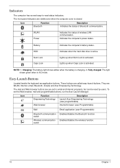
... Num Lock Caps Lock Indicates the computer's battery status. Enables/disables the wireless function. 10 Chapter 1 Easy-Launch Buttons Located beside the keyboard are pre-set the Web browser, mail and programmable buttons, run the Acer Launch Manager. To set to -read status indicators: The front panel indicators are visible even when...
... Num Lock Caps Lock Indicates the computer's battery status. Enables/disables the wireless function. 10 Chapter 1 Easy-Launch Buttons Located beside the keyboard are pre-set the Web browser, mail and programmable buttons, run the Acer Launch Manager. To set to -read status indicators: The front panel indicators are visible even when...
Aspire 6530/6530G Quick Guide
Page 36
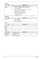
Bluetooth Item Type Features MDC Module Item Features WLAN Item Type Features Power Package Battery Item Manuafacturer Configuration Capacity Specification FOXCONN FOX_BRM_2.0 F/W 300 mini USB module • Bluetooth 1.2 qualified Embedded USB module • Extremely small size • Class 2 specification RF ...
Bluetooth Item Type Features MDC Module Item Features WLAN Item Type Features Power Package Battery Item Manuafacturer Configuration Capacity Specification FOXCONN FOX_BRM_2.0 F/W 300 mini USB module • Bluetooth 1.2 qualified Embedded USB module • Extremely small size • Class 2 specification RF ...
Aspire 6530/6530G Quick Guide
Page 45
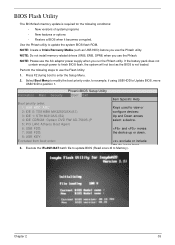
...: and moves 7: USB FDD: the device up or down. 8: USB KEY: Excluded from boot order: exclude or include the de ice to Memory). If the battery pack does not contain enough power to finish BIOS flash, the system will not boot as USB HDD) before you run the Phlash utility. NOTE...
...: and moves 7: USB FDD: the device up or down. 8: USB KEY: Excluded from boot order: exclude or include the de ice to Memory). If the battery pack does not contain enough power to finish BIOS flash, the system will not boot as USB HDD) before you run the Phlash utility. NOTE...
Aspire 6530/6530G Quick Guide
Page 52
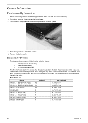
..., then disassemble the inside assembly frame in the succeeding disassembly sections illustrate the entire disassembly sequence. Unplug the AC adapter and all peripherals. 2. Remove the battery pack. Disassembly Process The disassembly process is divided into the following : 1. General Information Pre-disassembly Instructions Before proceeding with the disassembly procedure, make sure that...
..., then disassemble the inside assembly frame in the succeeding disassembly sections illustrate the entire disassembly sequence. Unplug the AC adapter and all peripherals. 2. Remove the battery pack. Disassembly Process The disassembly process is divided into the following : 1. General Information Pre-disassembly Instructions Before proceeding with the disassembly procedure, make sure that...

Aspire 6530/6530G Quick Guide
Page 53
Turn off system and peripherals power Disconnect power and signal cables from system Rem ove Battery Rem ove SD Dummy Rem ove NewCard Dummy Rem ove Lower Covers Rem ove DIMMs Rem ove VGA Module Rem ove TV Tuner Rem ove ...
Turn off system and peripherals power Disconnect power and signal cables from system Rem ove Battery Rem ove SD Dummy Rem ove NewCard Dummy Rem ove Lower Covers Rem ove DIMMs Rem ove VGA Module Rem ove TV Tuner Rem ove ...

Aspire 6530/6530G Quick Guide
Page 54
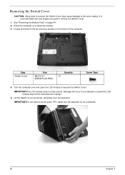
Slide and hold the battery release latch to the unlock position. 3. Removing the Battery Pack 1. Slide the battery lock/unlock latch to the release position (1), then slide out the battery pack from the main unit (2). 2 1 44 Chapter 3 Turn computer over. 2.
Slide and hold the battery release latch to the unlock position. 3. Removing the Battery Pack 1. Slide the battery lock/unlock latch to the release position (1), then slide out the battery pack from the main unit (2). 2 1 44 Chapter 3 Turn computer over. 2.

Aspire 6530/6530G Quick Guide
Page 57
See "Removing the ExpressCard dummy card" on page 45. 3. Carefully open the Lower Cover. Lower Cover 6. See "Removing the SD dummy card" on page 46. 4. Loosen the captive screws in the covers as shown. See "Removing the Battery Pack" on page 44. 2. HDD2 Cover 5. Remove the HDD2 Cover as shown. Chapter 3 47 Removing the Lower Covers 1.
See "Removing the ExpressCard dummy card" on page 45. 3. Carefully open the Lower Cover. Lower Cover 6. See "Removing the SD dummy card" on page 46. 4. Loosen the captive screws in the covers as shown. See "Removing the Battery Pack" on page 44. 2. HDD2 Cover 5. Remove the HDD2 Cover as shown. Chapter 3 47 Removing the Lower Covers 1.

Aspire 6530/6530G Quick Guide
Page 58
Repeat steps for the second DIMM module. 48 Chapter 3 Removing the DIMM Modules 1. Push out the release latches on page 47. 3. Remove the Lower Cover See "Removing the Lower Covers" on both sides of the DIMM socket to release the DIMM module. 4. See "Removing the Battery Pack" on page 44. 2. Remove the DIMM module. 5.
Repeat steps for the second DIMM module. 48 Chapter 3 Removing the DIMM Modules 1. Push out the release latches on page 47. 3. Remove the Lower Cover See "Removing the Lower Covers" on both sides of the DIMM socket to release the DIMM module. 4. See "Removing the Battery Pack" on page 44. 2. Remove the DIMM module. 5.

Aspire 6530/6530G Quick Guide
Page 60
Remove the Lower cover. Step TV Tuner Module Size M2.0*3.0-I-NI-NYLOK Quantity 2 Screw Type 50 Chapter 3 See "Removing the Lower Covers" on page 44. 2. Move the antenna cables away and remove the two screws to release the TV Tuner module and bracket assembly. NOTE: To ensure proper assembly, the antenna cable must be installed as shown. Disconnect the antenna cable from the TV Tuner board as shown. 4. See "Removing the Battery Pack" on page 47. 3. Removing the TV Tuner Module 1.
Remove the Lower cover. Step TV Tuner Module Size M2.0*3.0-I-NI-NYLOK Quantity 2 Screw Type 50 Chapter 3 See "Removing the Lower Covers" on page 44. 2. Move the antenna cables away and remove the two screws to release the TV Tuner module and bracket assembly. NOTE: To ensure proper assembly, the antenna cable must be installed as shown. Disconnect the antenna cable from the TV Tuner board as shown. 4. See "Removing the Battery Pack" on page 47. 3. Removing the TV Tuner Module 1.

Aspire 6530/6530G Quick Guide
Page 63
Removing the Main Hard Disk Drive Module 1. Remove the Lower Cover. Pull the HDD up as shown to the carrier. Step HDD Carrier Size M3*0.5+3.5I Quantity 4 Screw Type Chapter 3 53 See "Removing the Lower Covers" on top of it or placing heavy objects on page 47. 3. Remove the four screws securing the HDD to remove. Hold the Pull Tab and slide the HDD away from the connector. NOTE: To prevent damage to HDD, avoid pressing down on it . 4. See "Removing the Battery Pack" on page 44. 2.
Removing the Main Hard Disk Drive Module 1. Remove the Lower Cover. Pull the HDD up as shown to the carrier. Step HDD Carrier Size M3*0.5+3.5I Quantity 4 Screw Type Chapter 3 53 See "Removing the Lower Covers" on top of it or placing heavy objects on page 47. 3. Remove the four screws securing the HDD to remove. Hold the Pull Tab and slide the HDD away from the connector. NOTE: To prevent damage to HDD, avoid pressing down on it . 4. See "Removing the Battery Pack" on page 44. 2.

Aspire 6530/6530G Quick Guide
Page 65
Removing the Optical Disk Drive Module 1. Remove the screw securing the ODD module. Remove the Lower Cover. See "Removing the Lower Covers" on page 44. 2. Screw Type Chapter 3 55 Grasp the ODD module as shown and pull out of the bay. Step ODD Module Size M2.5*6.5-I (BZN(NYLOK-RED) Quantity 1 4. See "Removing the Battery Pack" on page 47. 3.
Removing the Optical Disk Drive Module 1. Remove the screw securing the ODD module. Remove the Lower Cover. See "Removing the Lower Covers" on page 44. 2. Screw Type Chapter 3 55 Grasp the ODD module as shown and pull out of the bay. Step ODD Module Size M2.5*6.5-I (BZN(NYLOK-RED) Quantity 1 4. See "Removing the Battery Pack" on page 47. 3.

Aspire 6530/6530G Quick Guide
Page 67
Remove the two securing screws from the HDD. See "Removing the Lower Covers" on page 44. 2. Remove the Battery. Remove the HDD2 Cover. See "Removing the Battery Pack" on page 47. 3. Step HDD2 Carrier Size M2.0*3.0-I (BKAG) (NYLOK) IRON Quantity 2 4. Grasp the Pull Tab and pull the HDD out of the bay as shown. Screw Type Chapter 3 57 Removing the Secondary Hard Disk Drive Module 1.
Remove the two securing screws from the HDD. See "Removing the Lower Covers" on page 44. 2. Remove the Battery. Remove the HDD2 Cover. See "Removing the Battery Pack" on page 47. 3. Step HDD2 Carrier Size M2.0*3.0-I (BKAG) (NYLOK) IRON Quantity 2 4. Grasp the Pull Tab and pull the HDD out of the bay as shown. Screw Type Chapter 3 57 Removing the Secondary Hard Disk Drive Module 1.
Aspire 6530/6530G Quick Guide
Page 70
... and open the LCD module to the outer casing. FFC cables are used to extend the LCD module beyond the manufacturer's design. 5. See "Removing the Battery Pack" on the underside. 60 Chapter 3 It is recommended that only fingers are still attached on page 44. 2. Removing the Switch Cover CAUTION: Using tools...
... and open the LCD module to the outer casing. FFC cables are used to extend the LCD module beyond the manufacturer's design. 5. See "Removing the Battery Pack" on the underside. 60 Chapter 3 It is recommended that only fingers are still attached on page 44. 2. Removing the Switch Cover CAUTION: Using tools...

Aspire 6530/6530G Quick Guide
Page 71
See "Removing the Battery Pack" on page 60. 3. Unlock the connector to remove the FFC cable. Chapter 3 61 Removing the Power Board 1. Lift the Switch Cover clear of the Switch Cover. Disconnect the two FFC cables as shown. 7. Expose the bottom side of the chassis. See "Removing the Switch Cover" on page 44. 2. 6.
See "Removing the Battery Pack" on page 60. 3. Unlock the connector to remove the FFC cable. Chapter 3 61 Removing the Power Board 1. Lift the Switch Cover clear of the Switch Cover. Disconnect the two FFC cables as shown. 7. Expose the bottom side of the chassis. See "Removing the Switch Cover" on page 44. 2. 6.
Aspire 6530/6530G Quick Guide
Page 129
... one by pressing Fn+F5 (on this model). Reconnect the power and reboot the computer. 4. Remove any stored power by removing the power cable and battery and holding down the power button for specific model procedures. 2. Reseat the memory modules. 7. Reference Product pages for 10 seconds. Make sure the computer has...
... one by pressing Fn+F5 (on this model). Reconnect the power and reboot the computer. 4. Remove any stored power by removing the power cable and battery and holding down the power button for specific model procedures. 2. Reseat the memory modules. 7. Reference Product pages for 10 seconds. Make sure the computer has...

Aspire 6530/6530G Quick Guide
Page 130
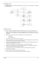
...to its highest level. Click and drag the Resolution slider to determine that the computer is still not resolved, see "Online Support Information" on battery alone as this may be defective and should be replaced. 5. If the Issue is not running on page 211. 120 Chapter 4 See "...permanent vertical/horizontal lines or dark spots display in the application. c. Check the display resolution is more than one year old, replace the CMOS battery. 2. Remove and reinstall the video driver. 8. Roll back the video driver to the previous version if updated. 7. If the computer is ...
...to its highest level. Click and drag the Resolution slider to determine that the computer is still not resolved, see "Online Support Information" on battery alone as this may be defective and should be replaced. 5. If the Issue is not running on page 211. 120 Chapter 4 See "...permanent vertical/horizontal lines or dark spots display in the application. c. Check the display resolution is more than one year old, replace the CMOS battery. 2. Remove and reinstall the video driver. 8. Roll back the video driver to the previous version if updated. 7. If the computer is ...

Aspire 6530/6530G Quick Guide
Page 139
... the issue is a good connection. Restore system and file settings from a known good date using System Restore. If the mouse uses a wireless connection, insert new batteries and confirm there is not fixed, repeat the preceding steps and select an earlier time and date. 9. Check Drive whether is OK. 2. Try an alternative...
... the issue is a good connection. Restore system and file settings from a known good date using System Restore. If the mouse uses a wireless connection, insert new batteries and confirm there is not fixed, repeat the preceding steps and select an earlier time and date. 9. Check Drive whether is OK. 2. Try an alternative...


