Quick Start Guide
Page 5
... the Bluetooth function. Backup key Launches Acer Backup Management for sound recording. 12 Acer CineDash 2.0 Capactive human interface featuring: Acer media console Arcade, hold, volume wheel and media controls. Charging: The light shows amber when the battery is active. Fully charged: The light...step data backup. 5 HDD1 Indicates when the hard disk drive is charging. 2. The center button serves as Acer Bio Protection fingerprint reader supporting Acer FingerNav 4-way control function (only for certain models). 10 Palmrest Comfortable support area for your computer. 7 ...
... the Bluetooth function. Backup key Launches Acer Backup Management for sound recording. 12 Acer CineDash 2.0 Capactive human interface featuring: Acer media console Arcade, hold, volume wheel and media controls. Charging: The light shows amber when the battery is active. Fully charged: The light...step data backup. 5 HDD1 Indicates when the hard disk drive is charging. 2. The center button serves as Acer Bio Protection fingerprint reader supporting Acer FingerNav 4-way control function (only for certain models). 10 Palmrest Comfortable support area for your computer. 7 ...

Quick Start Guide
Page 10
Note: Do not cover or obstruct the opening of the fan. 4 Battery bay Houses the computer's battery pack. 5 Battery release latch Releases the battery for removal. Locks the battery in position. 3 Ventilation slots and Enable the computer to stay cool, even cooling fan after prolonged use. English 10 Base view 1 2 5 3 4 # Icon Item 1 Hard disk bay Memory compartment 2 Battery lock Description Houses the computer's hard disk (secured with screws). Houses the computer's main memory.
Note: Do not cover or obstruct the opening of the fan. 4 Battery bay Houses the computer's battery pack. 5 Battery release latch Releases the battery for removal. Locks the battery in position. 3 Ventilation slots and Enable the computer to stay cool, even cooling fan after prolonged use. English 10 Base view 1 2 5 3 4 # Icon Item 1 Hard disk bay Memory compartment 2 Battery lock Description Houses the computer's hard disk (secured with screws). Houses the computer's main memory.
Quick Start Guide
Page 12
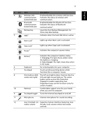
...) 2.8 kg (6.16 lbs.) with 6-cell battery pack ACPI 3.0 48.8 W 4400 mAh battery* 71 W 4800 mAh battery* 3-pin 90 W AC adapter ENERGY STAR®* 86-/87-/91-key keyboard Multi-gesture touchpad pointing device Acer Bio-Protection fingerprint reader Acer CineDash 2.0 ExpressCard®/54 slot Multi-in...; I/O interface • • • • • • • • • • • • • Integrated Acer Crystal Eye webcam* WLAN: • Intel® Wireless-WiFi Link 5100/5300 a/b/g/n* Wi-Fi®/WiMAX • Intel® Wireless WiFi Link 5150/5350* ...
...) 2.8 kg (6.16 lbs.) with 6-cell battery pack ACPI 3.0 48.8 W 4400 mAh battery* 71 W 4800 mAh battery* 3-pin 90 W AC adapter ENERGY STAR®* 86-/87-/91-key keyboard Multi-gesture touchpad pointing device Acer Bio-Protection fingerprint reader Acer CineDash 2.0 ExpressCard®/54 slot Multi-in...; I/O interface • • • • • • • • • • • • • Integrated Acer Crystal Eye webcam* WLAN: • Intel® Wireless-WiFi Link 5100/5300 a/b/g/n* Wi-Fi®/WiMAX • Intel® Wireless WiFi Link 5150/5350* ...
Service Guide
Page 7
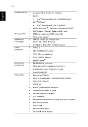
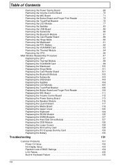
Table of Contents System Specifications 1 Features 1 System Block Diagram 4 Your Acer Notebook tour 5 Front View 5 Closed Front View 7 Rear View 7 Left View 7 Right View 9 Bottom View 10 TouchPad Basics (with fingerprint reader 11 Using the... Requirements 41 General Information 42 Pre-disassembly Instructions 42 Disassembly Process 42 External Module Disassembly Process 43 External Modules Disassembly Flowchart 43 Removing the Battery Pack 44 Removing the Express Dummy Card 45 Removing the SD Dummy Card 46 Removing the Lower Covers 47 Removing the Optical Drive Module ...
Table of Contents System Specifications 1 Features 1 System Block Diagram 4 Your Acer Notebook tour 5 Front View 5 Closed Front View 7 Rear View 7 Left View 7 Right View 9 Bottom View 10 TouchPad Basics (with fingerprint reader 11 Using the... Requirements 41 General Information 42 Pre-disassembly Instructions 42 Disassembly Process 42 External Module Disassembly Process 43 External Modules Disassembly Flowchart 43 Removing the Battery Pack 44 Removing the Express Dummy Card 45 Removing the SD Dummy Card 46 Removing the Lower Covers 47 Removing the Optical Drive Module ...
Service Guide
Page 8
... 86 Removing the Bluetooth Module 87 Removing the Card Reader Board 89 Removing the Hinge Wells 90 Removing the Mainboard 91 Removing the RTC Battery 92 Removing the VGA/MXM Card 93 Removing the Thermal Module 94 Removing the CPU 96 Main Module Reassembly Procedure 97 Replacing the CPU ... the ODD Module 128 Replacing the Lower Covers 129 Replacing the SD Dummy Card 129 Replacing the PCI Express Dummy Card 130 Replacing the Battery 130 Troubleshooting 131 Common Problems 131 Power On Issue 132 No Display Issue 133 Random Loss of BIOS Settings 134 LCD Failure 135 Built-...
... 86 Removing the Bluetooth Module 87 Removing the Card Reader Board 89 Removing the Hinge Wells 90 Removing the Mainboard 91 Removing the RTC Battery 92 Removing the VGA/MXM Card 93 Removing the Thermal Module 94 Removing the CPU 96 Main Module Reassembly Procedure 97 Replacing the CPU ... the ODD Module 128 Replacing the Lower Covers 129 Replacing the SD Dummy Card 129 Replacing the PCI Express Dummy Card 130 Replacing the Battery 130 Troubleshooting 131 Common Problems 131 Power On Issue 132 No Display Issue 133 Random Loss of BIOS Settings 134 LCD Failure 135 Built-...

Service Guide
Page 12
...8226; 383 (W) x 250 (D) x 26/37 (H) mm (15.1 x 9.9 x 1.03/1.5 inches) • 2.8 kg (6.16 lbs.) with 6-cell battery pack Communication • Integrated Acer Crystal Eye webcam* • WLAN: • Intel® Wireless-WiFi Link 5100/5300 a/b/g/n* • Wi-Fi®/WiMAX • Intel® Wireless ...• BIOS user, supervisor, HDD passwords • Kensington lock slot Power subsystem • ACPI 3.0 • 48.8 W 4400 mAh battery* • 71 W 4800 mAh battery* • 3-pin 90 W AC adapter • ENERGY STAR®* Special keys and controls • 86-/87-/91-key keyboard &#...
...8226; 383 (W) x 250 (D) x 26/37 (H) mm (15.1 x 9.9 x 1.03/1.5 inches) • 2.8 kg (6.16 lbs.) with 6-cell battery pack Communication • Integrated Acer Crystal Eye webcam* • WLAN: • Intel® Wireless-WiFi Link 5100/5300 a/b/g/n* • Wi-Fi®/WiMAX • Intel® Wireless ...• BIOS user, supervisor, HDD passwords • Kensington lock slot Power subsystem • ACPI 3.0 • 48.8 W 4400 mAh battery* • 71 W 4800 mAh battery* • 3-pin 90 W AC adapter • ENERGY STAR®* Special keys and controls • 86-/87-/91-key keyboard &#...
Service Guide
Page 16
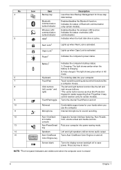
...disables the Bluetooth function. Charging: The light shows amber when the battery is activated. key 14 Speakers Left and right speakers deliver stereo audio output. 15 Acer CineBoost Turns Acer CineBoost Color Engine on and off. 10 Palmrest Comfortable support area ...is closed 6 Chapter 1 Battery1 Indicates the computer's battery status. 1. No. 4 5 Icon Item Backup key Bluetooth communication button/indicator Wireless LAN communication button/indicator HDD1 Num Lock1 Caps Lock1 Power1 Description Launches Acer Backup Management for certain models). 9 TouchPad toggle ...
...disables the Bluetooth function. Charging: The light shows amber when the battery is activated. key 14 Speakers Left and right speakers deliver stereo audio output. 15 Acer CineBoost Turns Acer CineBoost Color Engine on and off. 10 Palmrest Comfortable support area ...is closed 6 Chapter 1 Battery1 Indicates the computer's battery status. 1. No. 4 5 Icon Item Backup key Bluetooth communication button/indicator Wireless LAN communication button/indicator HDD1 Num Lock1 Caps Lock1 Power1 Description Launches Acer Backup Management for certain models). 9 TouchPad toggle ...

Service Guide
Page 20
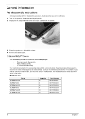
Enable the computer to stay cool, even after prolonged use. Note: Do not cover or obstruct the opening of the fan. Releases the battery for removal. 10 Chapter 1 Bottom View 1 2 5 3 4 No. 1 2 3 4 5 Icon Item Hard disk bay Memory compartment Battery lock Ventilation slots and cooling fan Battery bay Battery release latch Description Houses the computer's hard disk (secured with screws). Houses the computer's main memory. Locks the battery in position. Houses the computer's battery pack.
Enable the computer to stay cool, even after prolonged use. Note: Do not cover or obstruct the opening of the fan. Releases the battery for removal. 10 Chapter 1 Bottom View 1 2 5 3 4 No. 1 2 3 4 5 Icon Item Hard disk bay Memory compartment Battery lock Ventilation slots and cooling fan Battery bay Battery release latch Description Houses the computer's hard disk (secured with screws). Houses the computer's main memory. Locks the battery in position. Houses the computer's battery pack.

Service Guide
Page 33
... Definition Audio Codec with Dolby Digital Live • ENE KB926 for Keyboard Controller, Battery management Unit • JMB380 card reader Specification KB926 86-/87-/91-key keyboard Yes Yes Battery Item Vendor & model name Battery Type Pack capacity Number of battery cell Package configuration Specification 6 Cell 8 Cell Sanyo, Panasonic, Samsung, Sanyo, Sony Li-ion...
... Definition Audio Codec with Dolby Digital Live • ENE KB926 for Keyboard Controller, Battery management Unit • JMB380 card reader Specification KB926 86-/87-/91-key keyboard Yes Yes Battery Item Vendor & model name Battery Type Pack capacity Number of battery cell Package configuration Specification 6 Cell 8 Cell Sanyo, Panasonic, Samsung, Sanyo, Sony Li-ion...

Service Guide
Page 43
... diskette at hand, then you should create a Crisis Recovery Diskette before you use the AC adaptor power supply when you run the Phlash. 1. If the battery pack does not contain enough power to run the Phlash utility. Prepare a bootable diskette. 2. Chapter 2 31 Copy the flash utilities to update the system BIOS...
... diskette at hand, then you should create a Crisis Recovery Diskette before you use the AC adaptor power supply when you run the Phlash. 1. If the battery pack does not contain enough power to run the Phlash utility. Prepare a bootable diskette. 2. Chapter 2 31 Copy the flash utilities to update the system BIOS...
Service Guide
Page 54
... sequence to avoid damage to the system and all power and signal cables from the system. 3. Place the system on a flat, stable surface. 4. Remove the battery pack. For example, if you want to remove the main board, you do the following stages: • External module disassembly • Main unit disassembly •...
... sequence to avoid damage to the system and all power and signal cables from the system. 3. Place the system on a flat, stable surface. 4. Remove the battery pack. For example, if you want to remove the main board, you do the following stages: • External module disassembly • Main unit disassembly •...

Service Guide
Page 55
... power and signal cables from the mass produced model. External Module Disassembly Process IMPORTANT: The outside housing and color may vary from system Rem ove Battery Rem ove Dummy Cards Rem ove Lower Covers Rem ove ODD Rem ove HDD Rem ove DIMMs Rem ove TV Tuner Rem ove WLAN NOTE...
... power and signal cables from the mass produced model. External Module Disassembly Process IMPORTANT: The outside housing and color may vary from system Rem ove Battery Rem ove Dummy Cards Rem ove Lower Covers Rem ove ODD Rem ove HDD Rem ove DIMMs Rem ove TV Tuner Rem ove WLAN NOTE...

Service Guide
Page 56
Slide the battery lock to the release position (1), then lift out the battery pack from the main unit (2). 2 1 44 Chapter 3 Turn the computer over. 2. Slide and hold the battery release latch to the unlocked position. 3. Removing the Battery Pack 1.
Slide the battery lock to the release position (1), then lift out the battery pack from the main unit (2). 2 1 44 Chapter 3 Turn the computer over. 2. Slide and hold the battery release latch to the unlocked position. 3. Removing the Battery Pack 1.

Service Guide
Page 59
Loosen the four captive screws in the Memory/HDD and WLAN covers. Chapter 3 47 WLAN Cover 3. Removing the Lower Covers 1. Memory/ HDD Cover 4. See "Removing the Battery Pack" on page 44. 2. Carefully open the WLAN cover. Carefully open the Memory/HDD cover.
Loosen the four captive screws in the Memory/HDD and WLAN covers. Chapter 3 47 WLAN Cover 3. Removing the Lower Covers 1. Memory/ HDD Cover 4. See "Removing the Battery Pack" on page 44. 2. Carefully open the WLAN cover. Carefully open the Memory/HDD cover.

Service Guide
Page 68
... Rem ove Card Reader Board Rem ove Saddle Rem ove Subwoofer Rem ove USB Board Rem ove Hinge Wells Rem ove Mainboard Rem ove RTC Battery Rem ove VGA/MXM Card Rem ove Thermal Module Rem ove CPU Screw List Step LCD Module Right Saddle USB Board Card Reader Board Hinge...
... Rem ove Card Reader Board Rem ove Saddle Rem ove Subwoofer Rem ove USB Board Rem ove Hinge Wells Rem ove Mainboard Rem ove RTC Battery Rem ove VGA/MXM Card Rem ove Thermal Module Rem ove CPU Screw List Step LCD Module Right Saddle USB Board Card Reader Board Hinge...

Service Guide
Page 92
11. Remove the cables from the Mainboard. 80 Chapter 3 Disconnect the Conductive cable from the final cable clip as shown. 12. Pass the Antenna and Backlight cables through the space between the Battery Bay and Hinge well as shown. 13.
11. Remove the cables from the Mainboard. 80 Chapter 3 Disconnect the Conductive cable from the final cable clip as shown. 12. Pass the Antenna and Backlight cables through the space between the Battery Bay and Hinge well as shown. 13.

Service Guide
Page 104
To replace the battery, solder the new battery to the Mainboard. Removing the RTC Battery IMPORTANT: Follow local regulations for disposal of all batteries. 1. The RTC Battery is soldered to the connections shown. 92 Chapter 3 See "Removing the Mainboard" on page 91. 2.
To replace the battery, solder the new battery to the Mainboard. Removing the RTC Battery IMPORTANT: Follow local regulations for disposal of all batteries. 1. The RTC Battery is soldered to the connections shown. 92 Chapter 3 See "Removing the Mainboard" on page 91. 2.

Service Guide
Page 142
Slide the battery lock in place. 1 130 Chapter 3 Replacing the PCI Express Dummy Card Push the Express Dummy into the slot until an audible click indicates that the card is correctly inserted. Slide and hold the battery release latch to secure the battery in the direction shown to the release position (1), insert the battery pack and press down (2). 2 2. Replacing the Battery 1.
Slide the battery lock in place. 1 130 Chapter 3 Replacing the PCI Express Dummy Card Push the Express Dummy into the slot until an audible click indicates that the card is correctly inserted. Slide and hold the battery release latch to secure the battery in the direction shown to the release position (1), insert the battery pack and press down (2). 2 2. Replacing the Battery 1.
Service Guide
Page 145
... is by pressing Fn+F5. Chapter 4 133 Restart the computer. If the computer boots correctly, add the devices one by removing the power cable and battery and holding down the power button for specific model procedures. 2. Disconnect power and all external devices including port replicators or docking stations. On this model...
... is by pressing Fn+F5. Chapter 4 133 Restart the computer. If the computer boots correctly, add the devices one by removing the power cable and battery and holding down the power button for specific model procedures. 2. Disconnect power and all external devices including port replicators or docking stations. On this model...
Service Guide
Page 146
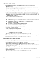
... the view settings and control/mouse wheel zoom feature in the application. NOTE: Ensure that : • The device is virus free. 3. d. See "Disassembly Process" on battery alone as this may be defective and should be replaced. 5. Minimize or close all Windows. If display size is missing from the operating system DVD.... 6. Check the Device Manager to the previous version if updated. 7. Random Loss of BIOS information, perform the following actions one year old, replace the CMOS battery. 2. Remove and reinstall the video driver. 8.
... the view settings and control/mouse wheel zoom feature in the application. NOTE: Ensure that : • The device is virus free. 3. d. See "Disassembly Process" on battery alone as this may be defective and should be replaced. 5. Minimize or close all Windows. If display size is missing from the operating system DVD.... 6. Check the Device Manager to the previous version if updated. 7. Random Loss of BIOS information, perform the following actions one year old, replace the CMOS battery. 2. Remove and reinstall the video driver. 8.


