Aspire 5920/5920G Service Guide
Page 57
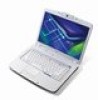
..., then disassemble the inside assembly frame in that need to be removed during servicing. For example, if you want to remove the system board, you on upper side Upper Case Assembly F*1 Modem Board Switch Board (for AS models) Lower Case F*1 Main Board F*2 Speaker Set F*2 Media Board (for AS models) F*1 Touchpad Bracket Touchpad Touchpad FFC Chapter 3 53
..., then disassemble the inside assembly frame in that need to be removed during servicing. For example, if you want to remove the system board, you on upper side Upper Case Assembly F*1 Modem Board Switch Board (for AS models) Lower Case F*1 Main Board F*2 Speaker Set F*2 Media Board (for AS models) F*1 Touchpad Bracket Touchpad Touchpad FFC Chapter 3 53

Aspire 5920/5920G Service Guide
Page 61
Remove the two screws fastening the wireless LAN card. 12. Take out the VGA board from the main unit. Take out the wireless LAN card from the main unit. 15. Disconnect the system fan cable as shown. Disconnect the main and auxiliary antenna from the DIMM socket (If the notebook has two memory, then repeat this step). 10. Removing the VGA Board and Thermal Module 13. Remove the memory from the wireless LAN card. 11. Chapter 3 57 Remove the four screws fastening the VGA board. 14. 9.
Remove the two screws fastening the wireless LAN card. 12. Take out the VGA board from the main unit. Take out the wireless LAN card from the main unit. 15. Disconnect the system fan cable as shown. Disconnect the main and auxiliary antenna from the DIMM socket (If the notebook has two memory, then repeat this step). 10. Removing the VGA Board and Thermal Module 13. Remove the memory from the wireless LAN card. 11. Chapter 3 57 Remove the four screws fastening the VGA board. 14. 9.
Aspire 5920/5920G Service Guide
Page 63
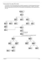
...screws securing the lower case assembly to the upper case assembly. 7. Chapter 3 59 Disconnect the keyboard cable from the main board and remove the keyboard from the main unit. 5. Turn the notebook over and gently pry up and towards you. 4. Disconnect the media button, Bluetooth and ...Wireless cables. 6. Remove the power board cover as shown. 3. Removing the Keyboard and LCD Module 1. Disconnect the speaker, DC-In, ...
...screws securing the lower case assembly to the upper case assembly. 7. Chapter 3 59 Disconnect the keyboard cable from the main board and remove the keyboard from the main unit. 5. Turn the notebook over and gently pry up and towards you. 4. Disconnect the media button, Bluetooth and ...Wireless cables. 6. Remove the power board cover as shown. 3. Removing the Keyboard and LCD Module 1. Disconnect the speaker, DC-In, ...
Aspire 5920/5920G Service Guide
Page 65
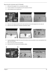
... and disconnect the cable from the power board. Disassembling the Main Unit Separate the Main Unit Into the Upper and the Lower Case Assembly 1. Remove the three screws fastening the power board. 4. Carefully detach the upper case assembly from the main board. 8. Disassembling the Lower Case Assembly Removing the Power Board 3. Disconnect the bluetooth cable from the...
... and disconnect the cable from the power board. Disassembling the Main Unit Separate the Main Unit Into the Upper and the Lower Case Assembly 1. Remove the three screws fastening the power board. 4. Carefully detach the upper case assembly from the main board. 8. Disassembling the Lower Case Assembly Removing the Power Board 3. Disconnect the bluetooth cable from the...

Aspire 5920/5920G Service Guide
Page 66
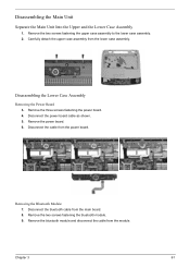
Remove the four screws fastening the subwoofer. 12. Remove the two screws fastening the MDC card module. 15. Disconnect the MDC card cable from the main board. 11. Remove the subwoofer. Disconnect the subwoofer cable from the main board. 14. Remove the MDC card module. 62 Chapter 3 Removing the MDC Card Module 13. Removing the Subwoofer 10.
Remove the four screws fastening the subwoofer. 12. Remove the two screws fastening the MDC card module. 15. Disconnect the MDC card cable from the main board. 11. Remove the subwoofer. Disconnect the subwoofer cable from the main board. 14. Remove the MDC card module. 62 Chapter 3 Removing the MDC Card Module 13. Removing the Subwoofer 10.

Aspire 5920/5920G Service Guide
Page 67
Remove the USB board. Removing the Main Board 21. Lift the USB board and disconnect the USB board cable. 18. Chapter 3 63 Removing the CPU 19. Use a flat screwdriver to the lower case. 22. Remove the screw fastening the USB board. 17. Remove the MSC cable and the screw fastening the main board to release the CPU lock (Turn counter clockwise). 20. Remove the CPU from the CPU socket carefully. Remove the main board. Removing the USB Board 16.
Remove the USB board. Removing the Main Board 21. Lift the USB board and disconnect the USB board cable. 18. Chapter 3 63 Removing the CPU 19. Use a flat screwdriver to the lower case. 22. Remove the screw fastening the USB board. 17. Remove the MSC cable and the screw fastening the main board to release the CPU lock (Turn counter clockwise). 20. Remove the CPU from the CPU socket carefully. Remove the main board. Removing the USB Board 16.
Aspire 5920/5920G Service Guide
Page 74
...be tested. Replace the keyboard. 3. Boot from the diagnostics diskette and start the diagnostics program. 2. If the error still remains: 1. Replace the main board. External CD-ROM Drive Check Do the following auxiliary input devices are supported by this computer: T Numeric keypad T External keyboard 68 Chapter 4 ... the external diskette drive/CD-ROM module. 3. See if CD-ROM Test is correctly seated in the connector on the system board. Replace the main board. NOTE: Make sure that the flexible cable extending from the keyboard is passed when the program runs to CD-ROM Test. ...
...be tested. Replace the keyboard. 3. Boot from the diagnostics diskette and start the diagnostics program. 2. If the error still remains: 1. Replace the main board. External CD-ROM Drive Check Do the following auxiliary input devices are supported by this computer: T Numeric keypad T External keyboard 68 Chapter 4 ... the external diskette drive/CD-ROM module. 3. See if CD-ROM Test is correctly seated in the connector on the system board. Replace the main board. NOTE: Make sure that the flexible cable extending from the keyboard is passed when the program runs to CD-ROM Test. ...
Aspire 5920/5920G Service Guide
Page 75
..., or hang the system. 1. A loose connection can cause an error. Press F2 in the following power sources: 1. then check that power is supplied. 3. Go to main board). 2. Power System Check To verify the symptom of the problem, power on the computer using each of these devices do not work, reconnect the cable...
..., or hang the system. 1. A loose connection can cause an error. Press F2 in the following power sources: 1. then check that power is supplied. 3. Go to main board). 2. Power System Check To verify the symptom of the problem, power on the computer using each of these devices do not work, reconnect the cable...


