Aspire 5510 Service Guide
Page 6
... Main 32 Advanced 34 Security 35 Boot 38 Exit 39 Chapter 3 Machine Disassembly and Replacement 40 General Information 41 Disassembly Procedure Flowchart 42 Removing the Battery Pack 44 Removing the HDD Module/the Memory and the Wireless LAN Card/the Thermal Module and the CPU/ODD Module and LCD Module 45...
... Main 32 Advanced 34 Security 35 Boot 38 Exit 39 Chapter 3 Machine Disassembly and Replacement 40 General Information 41 Disassembly Procedure Flowchart 42 Removing the Battery Pack 44 Removing the HDD Module/the Memory and the Wireless LAN Card/the Thermal Module and the CPU/ODD Module and LCD Module 45...
Aspire 5510 Service Guide
Page 8
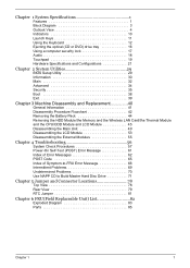
...-out jack with SPDIF support Infrared (FIR) port 3-in-1 card reader DC-in jack for AC adaptor TV RF input Composite input Battery T T T T 8-cell of Li-ion battery pack, (4400mAh) 4-cell of Li-ion battery pack, (2200mAh) 65W AC adaptor 3-hours battery life when support ATI X600 / 4-hours battery life when support Intel GFX 2 Chapter 1
...-out jack with SPDIF support Infrared (FIR) port 3-in-1 card reader DC-in jack for AC adaptor TV RF input Composite input Battery T T T T 8-cell of Li-ion battery pack, (4400mAh) 4-cell of Li-ion battery pack, (2200mAh) 65W AC adaptor 3-hours battery life when support ATI X600 / 4-hours battery life when support Intel GFX 2 Chapter 1
Aspire 5510 Service Guide
Page 11
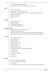
... line-out devices (e.g., speakers, Line-Out/ headphones). # Item "LDaeusnccrhipktieoyns" on page 10 Front View "Launch keys" on page 10 "Launch keys" on . # Icon Item Description 4 Battery indicator Lights when the battery is being charged. 5 Bluetooth Press to enable/disable Bluetooth function.
... line-out devices (e.g., speakers, Line-Out/ headphones). # Item "LDaeusnccrhipktieoyns" on page 10 Front View "Launch keys" on page 10 "Launch keys" on . # Icon Item Description 4 Battery indicator Lights when the battery is being charged. 5 Bluetooth Press to enable/disable Bluetooth function.
Aspire 5510 Service Guide
Page 15
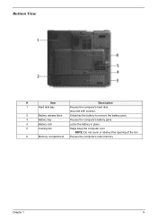
Bottom View # Item Description 1 Hard disk bay Houses the computer's hard disk (secured with screws). 2 Battery release latch Unlatches the battery to remove the battery pack. 3 Battery bay Houses the computer's battery pack. 4 Battery lock Locks the battery in place. 5 Cooling fan Helps keep the computer cool. NOTE: Do not cover or obstruct the opening of the fan. 6 Memory compartment Houses the computer's main memory Chapter 1 9
Bottom View # Item Description 1 Hard disk bay Houses the computer's hard disk (secured with screws). 2 Battery release latch Unlatches the battery to remove the battery pack. 3 Battery bay Houses the computer's battery pack. 4 Battery lock Locks the battery in place. 5 Cooling fan Helps keep the computer cool. NOTE: Do not cover or obstruct the opening of the fan. 6 Memory compartment Houses the computer's main memory Chapter 1 9
Aspire 5510 Service Guide
Page 16
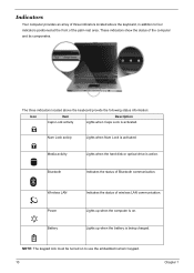
...Num Lock is on to four ##indicIateteommrs positioned at DtheeDsfcreroinsptctorioifpnthteiopnalm rest area. NOTE: The keypad lock must be turned on . Power Lights up when the battery is active. Indicators Your computer provides an array of Bluetooth communication. # Icon Item # Icon ItWeim reless LAN Description IndicateDs ethsecsrtaiptustioof wnireless LAN communication. Bluetooth...These indicators show the status of the computer and its componetns. Media activity Lights when the hard disk or optical drive is being charged. Battery Lights up when the computer is activated.
...Num Lock is on to four ##indicIateteommrs positioned at DtheeDsfcreroinsptctorioifpnthteiopnalm rest area. NOTE: The keypad lock must be turned on . Power Lights up when the battery is active. Indicators Your computer provides an array of Bluetooth communication. # Icon Item # Icon ItWeim reless LAN Description IndicateDs ethsecsrtaiptustioof wnireless LAN communication. Bluetooth...These indicators show the status of the computer and its componetns. Media activity Lights when the hard disk or optical drive is being charged. Battery Lights up when the computer is activated.
Aspire 5510 Service Guide
Page 30
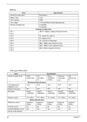
...Pin 6 Pin 7 Pin 8 Pin 9 Specification Sony/Sanyo Li-ion 65Wh 3.7V/cell/2000mAh High discharge rate 8-cell(65W) 4-cell(32W) Package configuration BATT+: Battery+, Battery Positive Terminal ID : Identify Pin (Note 1) B/I : Battery-In Pin TS : Connect to Thermister SMD : SMBus data interface I/O pin SMC : SMBus clock interface I/O pin GND... : Battery Negative Terminal LCD :15.4" WXGA LCD Item Vendor & model name LCD display area (diagonal, inch) Display technology Resolution Specification ...
...Pin 6 Pin 7 Pin 8 Pin 9 Specification Sony/Sanyo Li-ion 65Wh 3.7V/cell/2000mAh High discharge rate 8-cell(65W) 4-cell(32W) Package configuration BATT+: Battery+, Battery Positive Terminal ID : Identify Pin (Note 1) B/I : Battery-In Pin TS : Connect to Thermister SMD : SMBus data interface I/O pin SMC : SMBus clock interface I/O pin GND... : Battery Negative Terminal LCD :15.4" WXGA LCD Item Vendor & model name LCD display area (diagonal, inch) Display technology Resolution Specification ...
Aspire 5510 Service Guide
Page 31
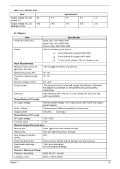
... name Delta 3-pin, 19V 3.95A, 64W Hipro 3-pin, 19V 3.95A, 65W Lite-on 3-pin, 19V 3.95A, 60W Details 65W Li-ion battery pack (8-cell) T 4-hour battery life (support intel GFX) T 3-hour battery life (support ATI X600) T 1.5-hour quick-charge, 3.5-hour charge-in use Input Requirements Maximum input current (A, @100Vac, full load) 1.8A max...
... name Delta 3-pin, 19V 3.95A, 64W Hipro 3-pin, 19V 3.95A, 65W Lite-on 3-pin, 19V 3.95A, 60W Details 65W Li-ion battery pack (8-cell) T 4-hour battery life (support intel GFX) T 3-hour battery life (support ATI X600) T 1.5-hour quick-charge, 3.5-hour charge-in use Input Requirements Maximum input current (A, @100Vac, full load) 1.8A max...
Aspire 5510 Service Guide
Page 47
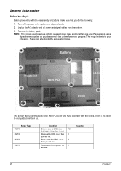
... and signal cables from the system. 3. There is for service purpose. Remove the Mini PCI cover 3 then you 1 will see . Remove the battery then you will see. Remove the battery pack. Turn off the power to worry about mix them up. The image below . Unplug the AC adapter and all peripherals. 2. Please...
... and signal cables from the system. 3. There is for service purpose. Remove the Mini PCI cover 3 then you 1 will see . Remove the battery then you will see. Remove the battery pack. Turn off the power to worry about mix them up. The image below . Unplug the AC adapter and all peripherals. 2. Please...
Aspire 5510 Service Guide
Page 50
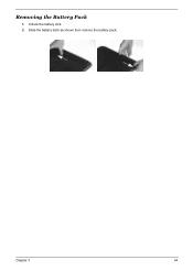
Chapter 3 44 Slide the battery latch as shown then remove the battery pack. Unlock the battery lock. 2. Removing the Battery Pack 1.
Chapter 3 44 Slide the battery latch as shown then remove the battery pack. Unlock the battery lock. 2. Removing the Battery Pack 1.
Aspire 5510 Service Guide
Page 64
... program (please refer to the diagnostic memory in the message window. NOTE: Make sure that the DIMM is supplied by the battery pack. Disconnect the power adapter and install the charged battery pack; Power System Check To verify the symptom of the following list: T "Check the Power Adapter" on page 59 T "...Check the Battery Pack" on page 60 Chapter 4 58 Memory check Memory errors might stop system operations, show error messages on the computer using each of the problem...
... program (please refer to the diagnostic memory in the message window. NOTE: Make sure that the DIMM is supplied by the battery pack. Disconnect the power adapter and install the charged battery pack; Power System Check To verify the symptom of the following list: T "Check the Power Adapter" on page 59 T "...Check the Battery Pack" on page 60 Chapter 4 58 Memory check Memory errors might stop system operations, show error messages on the computer using each of the problem...
Aspire 5510 Service Guide
Page 65
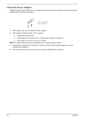
... Problems" on indicator does not light up, check the power cord of the power adapter cable. If the voltage is not corrected, see "Check the Battery Pack" on page 60. 59 Chapter 4 See the following : T Replace the System board.
... Problems" on indicator does not light up, check the power cord of the power adapter cable. If the voltage is not corrected, see "Check the Battery Pack" on page 60. 59 Chapter 4 See the following : T Replace the System board.
Aspire 5510 Service Guide
Page 66
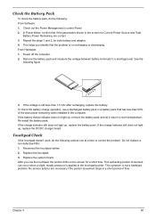
... control Panel 2. See the following actions one at a time to correct the problem. If the voltage is on the screen for both battery and adapter. 4. Replace the touchpad. 3. Replace the system board. This symptom is applied to room temperature. Touchpad Check If the touchpad...1 and 2, for a short time. Reconnect the touchpad cables. 2. Check out the Power Management in the computer. Remove the battery pack and measure the voltage between battery terminals 1(+) and 6(ground). If the charge indicator still does not light up , replace the DC/DC charger board. This self...
... control Panel 2. See the following actions one at a time to correct the problem. If the voltage is on the screen for both battery and adapter. 4. Replace the touchpad. 3. Replace the system board. This symptom is applied to room temperature. Touchpad Check If the touchpad...1 and 2, for a short time. Reconnect the touchpad cables. 2. Check out the Power Management in the computer. Remove the battery pack and measure the voltage between battery terminals 1(+) and 6(ground). If the charge indicator still does not light up , replace the DC/DC charger board. This self...
Aspire 5510 Service Guide
Page 68
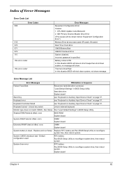
...Thermal critical High In this situation BIOS will be shown before "Equipment Configuration Error") Memory Error at offset: nnnn DIMM System board System battery is specified. System CMOS checksum bad - Keyboard locked - Shadow RAM Failed at offset: nnnn BIOS ROM System board System RAM Failed at... offset: nnnn DIMM System board Extended RAM Failed at xxxx:xxxx:xxxxh (R:xxxxh, W:xxxxh) Real Time Clock Error CMOS Battery Bad CMOS Checksum Error System disabled. Error Message List Error Messages FRU/Action in BIOS Setup Utility. "Load Default Settings" in BIOS...
...Thermal critical High In this situation BIOS will be shown before "Equipment Configuration Error") Memory Error at offset: nnnn DIMM System board System battery is specified. System CMOS checksum bad - Keyboard locked - Shadow RAM Failed at offset: nnnn BIOS ROM System board System RAM Failed at... offset: nnnn DIMM System board Extended RAM Failed at xxxx:xxxx:xxxxh (R:xxxxh, W:xxxxh) Real Time Clock Error CMOS Battery Bad CMOS Checksum Error System disabled. Error Message List Error Messages FRU/Action in BIOS Setup Utility. "Load Default Settings" in BIOS...
Aspire 5510 Service Guide
Page 69
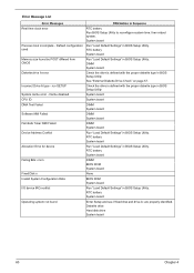
...Load Default Settings" in BIOS Setup Utility. run SETUP Check the drive is defined with the proper diskette type in BIOS Setup Utility. RTC battery System board Operating system not found by POST differed from CMOS Run "Load Default Settings" in BIOS Setup Utility System cache error - DIMM...BIOS Setup Utility. Error Message List Error Messages FRU/Action in BIOS Setup Utility See "External Diskette Drive Check" on page 57. RTC battery System board Memory size found Enter Setup and see if fixed disk and drive A: are properly identified. Diskette drive Hard disk drive System ...
...Load Default Settings" in BIOS Setup Utility. run SETUP Check the drive is defined with the proper diskette type in BIOS Setup Utility. RTC battery System board Operating system not found by POST differed from CMOS Run "Load Default Settings" in BIOS Setup Utility System cache error - DIMM...BIOS Setup Utility. Error Message List Error Messages FRU/Action in BIOS Setup Utility See "External Diskette Drive Check" on page 57. RTC battery System board Memory size found Enter Setup and see if fixed disk and drive A: are properly identified. Diskette drive Hard disk drive System ...
Aspire 5510 Service Guide
Page 70
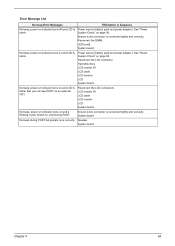
... "Power System Check" on and LCD is blank. LED board. No beep, power-on indicator turns on page 58. Power source (battery pack and power adapter). But you can see POST on LCD during POST but system runs correctly. Reconnect the LCD connectors LCD inverter ID...turns off and LCD is connected tightly and correctly System board No beep during POST. Speaker System board Chapter 4 64 System board. Power source (battery pack and power adapter). Ensure every connector is blank. Ensure every connector is blank. Error Message List No beep Error Messages FRU/Action in ...
... "Power System Check" on and LCD is blank. LED board. No beep, power-on indicator turns on page 58. Power source (battery pack and power adapter). But you can see POST on LCD during POST but system runs correctly. Reconnect the LCD connectors LCD inverter ID...turns off and LCD is connected tightly and correctly System board No beep during POST. Speaker System board Chapter 4 64 System board. Power source (battery pack and power adapter). Ensure every connector is blank. Ensure every connector is blank. Error Message List No beep Error Messages FRU/Action in ...
Aspire 5510 Service Guide
Page 72
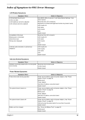
..."Power System Check" on page 60. Hold and press the power switch for more than 4 seconds. System board See "Check the Battery Pack" on page 58. Keyboard (if contrast and brightness function key doesn't work LCD is too dark LCD brightness cannot be adjusted ...to -FRU Error Message LCD-Related Symptoms Symptom / Error LCD backlight doesn't work ). Battery pack Power adapter Hard drive & battery connection board System board Power source (battery pack and power adapter). Battery can't be adjusted Unreadable LCD screen Missing pels in Sequence Indicator incorrectly remains off . See...
..."Power System Check" on page 60. Hold and press the power switch for more than 4 seconds. System board See "Check the Battery Pack" on page 58. Keyboard (if contrast and brightness function key doesn't work LCD is too dark LCD brightness cannot be adjusted ...to -FRU Error Message LCD-Related Symptoms Symptom / Error LCD backlight doesn't work ). Battery pack Power adapter Hard drive & battery connection board System board Power source (battery pack and power adapter). Battery can't be adjusted Unreadable LCD screen Missing pels in Sequence Indicator incorrectly remains off . See...
Aspire 5510 Service Guide
Page 73
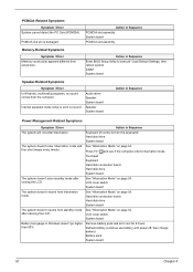
... slot assembly Memory-Related Symptoms Symptom / Error Memory count (size) appears different from hibernation mode. LCD cover switch System board Battery fuel gauge in Sequence Enter BIOS Setup Utility to execute "Load Default Settings, then reboot system. Press Fn+oand see if ...in Sequence The system will not enter hibernation Keyboard (if control is damaged. Remove battery pack and let it cool for 2 hours Refresh battery (continue use battery until power off, then charge battery) Battery pack System board 67 Chapter 4 LCD cover switch System board The system doesn't resume...
... slot assembly Memory-Related Symptoms Symptom / Error Memory count (size) appears different from hibernation mode. LCD cover switch System board Battery fuel gauge in Sequence Enter BIOS Setup Utility to execute "Load Default Settings, then reboot system. Press Fn+oand see if ...in Sequence The system will not enter hibernation Keyboard (if control is damaged. Remove battery pack and let it cool for 2 hours Refresh battery (continue use battery until power off, then charge battery) Battery pack System board 67 Chapter 4 LCD cover switch System board The system doesn't resume...
Aspire 5510 Service Guide
Page 76
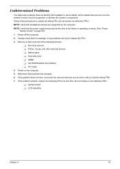
...-defective FRU: T System board T LCD assembly Chapter 4 70 Power-off the computer. 2. If the problem remains, replace the following devices: T Non-Acer devices T Printer, mouse, and other external devices T Battery pack T Hard disk drive T DIMM T CD-ROM/Diskette drive Module T PC Cards 4. If the problem does not recur, reconnect the removed devices...
...-defective FRU: T System board T LCD assembly Chapter 4 70 Power-off the computer. 2. If the problem remains, replace the following devices: T Non-Acer devices T Printer, mouse, and other external devices T Battery pack T Hard disk drive T DIMM T CD-ROM/Diskette drive Module T PC Cards 4. If the problem does not recur, reconnect the removed devices...
Aspire 5510 Service Guide
Page 90
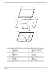
Item 1 2 3 4 5 6 7 8 9 10 Description LCD bezel LCD hinge(left) LCD hinge(right) LCD cover Middle cover Upper case VGA support plate VGA sink CPU support M29 thermal module Item 11 12 13 14 15 16 17 18 19 20 Description Lower case without media bay CPU cover w/ TV tuner assy DDR cover HDD bracket HDD cover DVD dual assy Mainboard C/S CIR only Battery TV tuner board Mainboard mylar Chapter 6 84
Item 1 2 3 4 5 6 7 8 9 10 Description LCD bezel LCD hinge(left) LCD hinge(right) LCD cover Middle cover Upper case VGA support plate VGA sink CPU support M29 thermal module Item 11 12 13 14 15 16 17 18 19 20 Description Lower case without media bay CPU cover w/ TV tuner assy DDR cover HDD bracket HDD cover DVD dual assy Mainboard C/S CIR only Battery TV tuner board Mainboard mylar Chapter 6 84
Aspire 5510 Service Guide
Page 93
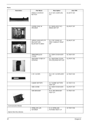
Parts Illustration Part Name MIDDLE COVER W/ BUTTON Description ZL1C K/B COVER (AS) S.P. Acer P/N 42.A27V7.001 LOWER CASE W/ SPEAKER ZL7 BASE ASSY W/O MEDIA BAY S/P 60.A76V7.001 UPPER CASE W/TP, TP BRACKET, MIC, BLUETOOTH CABLE ZL2 TOP COVER ... ASSY S/P ZL7 HEATSINK COVER W/O DOCKING W/TV S/P 42.T63V7.001 42.A76V7.002 3 IN 1 COVER ZL2 3 IN 1 COVER ASSY S.P. 42.T63V7.003 DUMMY BATTERY HDD COVER HDD BRACKET ZL7 DUMMY BATTERY ASSY S/P ZL7 HDD COVER ASSY S/P ZL1A HDD BRACKET ASSY S.P. 60.T50V7.010 42.A76V7.001 33.T50V7.001 Communication Module Optical Disk...
Parts Illustration Part Name MIDDLE COVER W/ BUTTON Description ZL1C K/B COVER (AS) S.P. Acer P/N 42.A27V7.001 LOWER CASE W/ SPEAKER ZL7 BASE ASSY W/O MEDIA BAY S/P 60.A76V7.001 UPPER CASE W/TP, TP BRACKET, MIC, BLUETOOTH CABLE ZL2 TOP COVER ... ASSY S/P ZL7 HEATSINK COVER W/O DOCKING W/TV S/P 42.T63V7.001 42.A76V7.002 3 IN 1 COVER ZL2 3 IN 1 COVER ASSY S.P. 42.T63V7.003 DUMMY BATTERY HDD COVER HDD BRACKET ZL7 DUMMY BATTERY ASSY S/P ZL7 HDD COVER ASSY S/P ZL1A HDD BRACKET ASSY S.P. 60.T50V7.010 42.A76V7.001 33.T50V7.001 Communication Module Optical Disk...


