Service Guide
Page 7
...1 Features 1 Optical Media Drive 2 System Block Diagram 5 Your Acer Notebook tour 6 Front View 6 Closed Front View 7 Left View 7 Right View 9 Bottom View 9 Indicators 10 TouchPad Basics 11 Using the Keyboard 12 Lock Keys and embedded numeric keypad 12 Windows Keys 13 Hot ...BIOS Flash Utilities 31 DOS Flash Utility 32 WinFlash Utility 34 Remove HDD/BIOS Password Utilities 35 Machine Disassembly and Replacement 43 Disassembly Requirements 43 Pre-disassembly Instructions 44 Disassembly Process 44 External Module Disassembly Process 45 External Modules Disassembly Flowchart...
...1 Features 1 Optical Media Drive 2 System Block Diagram 5 Your Acer Notebook tour 6 Front View 6 Closed Front View 7 Left View 7 Right View 9 Bottom View 9 Indicators 10 TouchPad Basics 11 Using the Keyboard 12 Lock Keys and embedded numeric keypad 12 Windows Keys 13 Hot ...BIOS Flash Utilities 31 DOS Flash Utility 32 WinFlash Utility 34 Remove HDD/BIOS Password Utilities 35 Machine Disassembly and Replacement 43 Disassembly Requirements 43 Pre-disassembly Instructions 44 Disassembly Process 44 External Module Disassembly Process 45 External Modules Disassembly Flowchart...
Service Guide
Page 8
... Main Module Reassembly Procedure 98 Replacing the CPU 98 Replacing the CPU Fan 99 Replacing the Thermal Module 99 Replacing the Mainboard 100 Replacing the TouchPad Bracket 101 Replacing the Left Speaker Module 103 Replacing the Power Board 103 Replacing the Upper Cover 105 Replacing the LCD Module 109 Replacing the Keyboard 114 Replacing the Switch Cover 115 Replacing the Hard Disk Drive...
... Main Module Reassembly Procedure 98 Replacing the CPU 98 Replacing the CPU Fan 99 Replacing the Thermal Module 99 Replacing the Mainboard 100 Replacing the TouchPad Bracket 101 Replacing the Left Speaker Module 103 Replacing the Power Board 103 Replacing the Upper Cover 105 Replacing the LCD Module 109 Replacing the Keyboard 114 Replacing the Switch Cover 115 Replacing the Hard Disk Drive...
Service Guide
Page 54
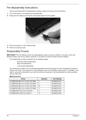
Place the system on a flat, stable surface. 4. Remove the battery pack. Disassembly Process IMPORTANT: The LCD Module cannot be replaced. For example, if you want to remove the mainboard, you do the following stages: • External module disassembly • Main unit disassembly • LCD module ... part of the hardware components. The disassembly process is faulty, such as the camera, antenna or LCD panel, the whole module must first remove the keyboard, then disassemble the inside assembly frame in the succeeding disassembly sections illustrate the entire disassembly sequence.
Place the system on a flat, stable surface. 4. Remove the battery pack. Disassembly Process IMPORTANT: The LCD Module cannot be replaced. For example, if you want to remove the mainboard, you do the following stages: • External module disassembly • Main unit disassembly • LCD module ... part of the hardware components. The disassembly process is faulty, such as the camera, antenna or LCD panel, the whole module must first remove the keyboard, then disassemble the inside assembly frame in the succeeding disassembly sections illustrate the entire disassembly sequence.
Service Guide
Page 124
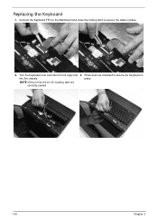
Connect the Keyboard FFC to the Mainboard and close the locking latch to secure the Keyboard in place. 2. Turn the Keyboard over and insert it front edge first into the chassis. Press down as indicated to secure the cable in place. 114 Chapter 3 NOTE: Ensure that the six (6) locating tabs are correctly seated. 3. Replacing the Keyboard 1.
Connect the Keyboard FFC to the Mainboard and close the locking latch to secure the Keyboard in place. 2. Turn the Keyboard over and insert it front edge first into the chassis. Press down as indicated to secure the cable in place. 114 Chapter 3 NOTE: Ensure that the six (6) locating tabs are correctly seated. 3. Replacing the Keyboard 1.
Service Guide
Page 137
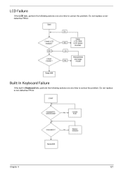
LCD Failure If the LCD fails, perform the following actions one at a time to correct the problem. Do not replace a nondefective FRUs: Built-In Keyboard Failure If the built-in Keyboard fails, perform the following actions one at a time to correct the problem. Do not replace a non-defective FRUs: Chapter 4 127
LCD Failure If the LCD fails, perform the following actions one at a time to correct the problem. Do not replace a nondefective FRUs: Built-In Keyboard Failure If the built-in Keyboard fails, perform the following actions one at a time to correct the problem. Do not replace a non-defective FRUs: Chapter 4 127
Service Guide
Page 245
...Replacing 90 B Battery Replacing...Replacing 94 caps lock on indicator 7, 10 Common Problems 124 computer on indicator 10 CPU Removing 79 Replacing 98 CPU Fan Removing 78 Index Replacing 99 D DIMM Modules Removing 51 Replacing... 119 Display 5 display hotkeys 14 E EasyTouch Failure 134 External Module Disassembly Flowchart 45 F Features 1 Flash Utility 31 FPC Cable Removing 85 FRU (Field Replaceable... Unit) List 151 H Hard Disk Drive Removing 55 Replacing 115 HDTV Switch Failure ...
...Replacing 90 B Battery Replacing...Replacing 94 caps lock on indicator 7, 10 Common Problems 124 computer on indicator 10 CPU Removing 79 Replacing 98 CPU Fan Removing 78 Index Replacing 99 D DIMM Modules Removing 51 Replacing... 119 Display 5 display hotkeys 14 E EasyTouch Failure 134 External Module Disassembly Flowchart 45 F Features 1 Flash Utility 31 FPC Cable Removing 85 FRU (Field Replaceable... Unit) List 151 H Hard Disk Drive Removing 55 Replacing 115 HDTV Switch Failure ...
Service Guide
Page 246
Removing 58 Replacing 114 Keyboard Failure 127 L LCD Bezel Removing 81 Replacing 96 LCD Brackets Removing 85 Replacing 93 LCD Cable Replacing 93 LCD Failure 127 LCD Module Removing 60 Replacing 109 LCD Module Disassembly Flowchart 80 LCD Module Reassembly Procedure 90 LCD Panel Removing 83, 84, 95 Replacing 93 Left Speaker Module Removing 70 Replacing 103 Lower Covers...
Removing 58 Replacing 114 Keyboard Failure 127 L LCD Bezel Removing 81 Replacing 96 LCD Brackets Removing 85 Replacing 93 LCD Cable Replacing 93 LCD Failure 127 LCD Module Removing 60 Replacing 109 LCD Module Disassembly Flowchart 80 LCD Module Reassembly Procedure 90 LCD Panel Removing 83, 84, 95 Replacing 93 Left Speaker Module Removing 70 Replacing 103 Lower Covers...


