Service Guide
Page 7
Table of Contents System Specifications 1 Features 1 Optical Media Drive 2 System Block Diagram 5 Your Acer Notebook tour 6 Front View 6 Closed Front View 7 Left View 7 Right View 9 Bottom View 9 Indicators 10 TouchPad Basics 11 Using the Keyboard 12 Lock Keys ... keypad 12 Windows Keys 13 Hot Keys 14 Hardware Specifications and Configurations 15 System Utilities 23 BIOS Setup Utility 23 Navigating the BIOS Utility 23 HM52-MV Intel BIOS 24 Information 24 Main 25 Security 26 Boot 29 Exit 30 BIOS Flash Utilities 31 DOS Flash Utility 32 WinFlash Utility 34 Remove HDD...
Table of Contents System Specifications 1 Features 1 Optical Media Drive 2 System Block Diagram 5 Your Acer Notebook tour 6 Front View 6 Closed Front View 7 Left View 7 Right View 9 Bottom View 9 Indicators 10 TouchPad Basics 11 Using the Keyboard 12 Lock Keys ... keypad 12 Windows Keys 13 Hot Keys 14 Hardware Specifications and Configurations 15 System Utilities 23 BIOS Setup Utility 23 Navigating the BIOS Utility 23 HM52-MV Intel BIOS 24 Information 24 Main 25 Security 26 Boot 29 Exit 30 BIOS Flash Utilities 31 DOS Flash Utility 32 WinFlash Utility 34 Remove HDD...
Service Guide
Page 8
... the SD Dummy Card 120 Replacing the Battery 121 Troubleshooting 123 Common Problems 123 Power On Issue 124 No Display Issue 125 Random Loss of BIOS Settings 126 LCD Failure 127 Built-In Keyboard Failure 127 TouchPad Failure 128 Internal Speaker Failure 128 HDD Not Operating Correctly 130 ODD Failure 131...
... the SD Dummy Card 120 Replacing the Battery 121 Troubleshooting 123 Common Problems 123 Power On Issue 124 No Display Issue 125 Random Loss of BIOS Settings 126 LCD Failure 127 Built-In Keyboard Failure 127 TouchPad Failure 128 Internal Speaker Failure 128 HDD Not Operating Correctly 130 ODD Failure 131...
Service Guide
Page 9
... Codes 137 Jumper and Connector Locations 145 Top View 145 Bottom View 146 Power Board 147 Clearing Password Check and BIOS Recovery 148 Clearing Password Check 148 Clear CMOS Jumper 149 BIOS Recovery by Crisis Disk 150 FRU (Field Replaceable Unit) List 151 JE50_MV Exploded Diagrams 152 Main Assembly 152 Rear Assembly...
... Codes 137 Jumper and Connector Locations 145 Top View 145 Bottom View 146 Power Board 147 Clearing Password Check and BIOS Recovery 148 Clearing Password Check 148 Clear CMOS Jumper 149 BIOS Recovery by Crisis Disk 150 FRU (Field Replaceable Unit) List 151 JE50_MV Exploded Diagrams 152 Main Assembly 152 Rear Assembly...
Service Guide
Page 12
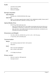
...8226; • • One built-in mono speaker Built-in microphone MS-Sound compatible Storage subsystem Aspire 5334/5734Z • Hard disk drive: 160/250/320/500/640 GB or larger Aspire 5734Z • Multi-in-1 card reader, supporting Secure Digital™ (SD), MultiMediaCard (MMC), Memory... (D) x 26.8/39.6 (H) mm (14.51 x 9.61 x 1.04/1.54 inches) • 2.7 kg (6.0 lbs.) with 6-cell battery pack Communication Webcam • Acer Crystal Eye webcam with 1280 x 1024 resolution • Microphone WLAN • 802.11 b/g/n Wi-Fi CERTIFIED™ • 802.11 b/g Wi-Fi CERTIFIED™ LAN...
...8226; • • One built-in mono speaker Built-in microphone MS-Sound compatible Storage subsystem Aspire 5334/5734Z • Hard disk drive: 160/250/320/500/640 GB or larger Aspire 5734Z • Multi-in-1 card reader, supporting Secure Digital™ (SD), MultiMediaCard (MMC), Memory... (D) x 26.8/39.6 (H) mm (14.51 x 9.61 x 1.04/1.54 inches) • 2.7 kg (6.0 lbs.) with 6-cell battery pack Communication Webcam • Acer Crystal Eye webcam with 1280 x 1024 resolution • Microphone WLAN • 802.11 b/g/n Wi-Fi CERTIFIED™ • 802.11 b/g Wi-Fi CERTIFIED™ LAN...
Service Guide
Page 24
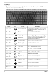
... employs hotkeys or key combinations to the previous media file. Return to access most of the computer's controls like screen brightness, volume output and the BIOS utility.
... employs hotkeys or key combinations to the previous media file. Return to access most of the computer's controls like screen brightness, volume output and the BIOS utility.
Service Guide
Page 26
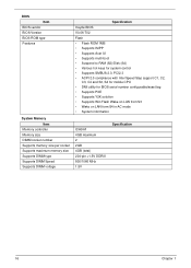
... memory size per socket Supports maximum memory size Supports DIMM type Supports DIMM Speed Supports DIMM voltage Specification Insyde BIOS V0.06-T02 Flash • Flash ROM 1MB • Supports ISIPP • Supports Acer UI • Supports multi-boot • Suspend to RAM (S3)/Disk (S4) • Various hot-keys for system...
... memory size per socket Supports maximum memory size Supports DIMM type Supports DIMM Speed Supports DIMM voltage Specification Insyde BIOS V0.06-T02 Flash • Flash ROM 1MB • Supports ISIPP • Supports Acer UI • Supports multi-boot • Suspend to RAM (S3)/Disk (S4) • Various hot-keys for system...
Service Guide
Page 33
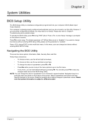
...encounter configuration problems, you want to run this carefully when making changes to different models. You can change boot device without entering BIOS Setup Utility, please set to enter Setup" message is prompted on the bottom of the screen. Chapter 2 23 Press during POST... refer to enter setup. Your computer is a hardware configuration program built into your computer's BIOS (Basic Input/ Output System). System Utilities Chapter 2 BIOS Setup Utility The BIOS Setup Utility is already properly configured and optimized, and you can change the value of the...
...encounter configuration problems, you want to run this carefully when making changes to different models. You can change boot device without entering BIOS Setup Utility, please set to enter Setup" message is prompted on the bottom of the screen. Chapter 2 23 Press during POST... refer to enter setup. Your computer is a hardware configuration program built into your computer's BIOS (Basic Input/ Output System). System Utilities Chapter 2 BIOS Setup Utility The BIOS Setup Utility is already properly configured and optimized, and you can change the value of the...
Service Guide
Page 34
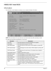
...the CPU type and speed of your reference only. This field displays the serial number of this screen. HM52-MV Intel BIOS Information The Information screen displays a summary of the system. The table below describes the parameters in this system. InsydeH20 ...Number: ATAPI Model Name: System BIOS Version: VGA BIOS Version: Serial Number: Asset Tag Number: Product Name: Manufacturer Name: UUID: Intel(R) Celeron(R) CPU 900 @ 2.20GHz 2.20GHz Hitachi HTS545016B9A300 100314PBNK06ASC6HJ5L HL-DT-STDVDRAM GT30N V0.03 Intel V1800 Aspire 5334 Acer 65333665-6330-6439-3036-705AB6D75AB6 F1...
...the CPU type and speed of your reference only. This field displays the serial number of this screen. HM52-MV Intel BIOS Information The Information screen displays a summary of the system. The table below describes the parameters in this system. InsydeH20 ...Number: ATAPI Model Name: System BIOS Version: VGA BIOS Version: Serial Number: Asset Tag Number: Product Name: Manufacturer Name: UUID: Intel(R) Celeron(R) CPU 900 @ 2.20GHz 2.20GHz Hitachi HTS545016B9A300 100314PBNK06ASC6HJ5L HL-DT-STDVDRAM GT30N V0.03 Intel V1800 Aspire 5334 Acer 65333665-6330-6439-3036-705AB6D75AB6 F1...

Service Guide
Page 36
.... Settings in this screen. When user password is required or not while the events defined in boldface are prompted to set , this password protects the BIOS Setup Utility from unauthorized access. Press Enter to enter a password, you are the default and suggested parameter settings. Option Clear or Set Clear or Set... the hard disk password. Shows the setting of password must be grayed out if the user password was used to set , this password protects the BIOS Setup Utility from unauthorized access. Don't forget your password.
.... Settings in this screen. When user password is required or not while the events defined in boldface are prompted to set , this password protects the BIOS Setup Utility from unauthorized access. Press Enter to enter a password, you are the default and suggested parameter settings. Option Clear or Set Clear or Set... the hard disk password. Shows the setting of password must be grayed out if the user password was used to set , this password protects the BIOS Setup Utility from unauthorized access. Don't forget your password.
Service Guide
Page 37
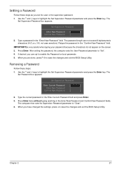
Press Enter. When you have changed the settings, press u to save the changes and exit the BIOS Setup Utility. Use the ↑ and ↓ keys to "Set". 4. Press Enter twice without typing anything in the "Enter New Password" field. Type a ... New Password fields. Type the current password in the "Confirm New Password" field. The password length can opt to save the changes and exit the BIOS Setup Utility. Removing a Password Follow these steps as you can not exceed 8 alphanumeric characters (A-Z, a-z, 0-9, not case sensitive). The Set Password box appears: Set ...
Press Enter. When you have changed the settings, press u to save the changes and exit the BIOS Setup Utility. Use the ↑ and ↓ keys to "Set". 4. Press Enter twice without typing anything in the "Enter New Password" field. Type a ... New Password fields. Type the current password in the "Confirm New Password" field. The password length can opt to save the changes and exit the BIOS Setup Utility. Removing a Password Follow these steps as you can not exceed 8 alphanumeric characters (A-Z, a-z, 0-9, not case sensitive). The Set Password box appears: Set ...
Service Guide
Page 38
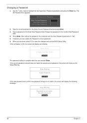
... match the actual current password, the screen will display as following message. Use the ↑ and ↓ keys to save the changes and exit the BIOS Setup Utility. After setting the password, the computer sets the User Password parameter to "Set". 5. Re-enter password. [Continue] 28 Chapter 2 Changing a Password 1. Retype the...
... match the actual current password, the screen will display as following message. Use the ↑ and ↓ keys to save the changes and exit the BIOS Setup Utility. After setting the password, the computer sets the User Password parameter to "Set". 5. Re-enter password. [Continue] 28 Chapter 2 Changing a Password 1. Retype the...

Service Guide
Page 40
... Load Setup Defaults Discard Changes Save Changes Rev. 3.5 Item Specific Help Exit System Setup and save or discard any changes you made and quit the BIOS Utility.
... Load Setup Defaults Discard Changes Save Changes Rev. 3.5 Item Specific Help Exit System Setup and save or discard any changes you made and quit the BIOS Utility.
Service Guide
Page 41
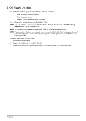
... function. NOTE: Do not install memory-related drivers (XMS, EMS, DPMI) when you may not boot the system because the BIOS is required for the following conditions: • New versions of system programs • New features or options • Restore... a BIOS when it becomes corrupted. Prepare a bootable diskette. 2. Copy the flash utilities to finish BIOS flash, you use the Flash. Chapter 2 31 BIOS Flash Utilities The BIOS flash memory update is not completely loaded. If the battery pack does not ...
... function. NOTE: Do not install memory-related drivers (XMS, EMS, DPMI) when you may not boot the system because the BIOS is required for the following conditions: • New versions of system programs • New features or options • Restore... a BIOS when it becomes corrupted. Prepare a bootable diskette. 2. Copy the flash utilities to finish BIOS flash, you use the Flash. Chapter 2 31 BIOS Flash Utilities The BIOS flash memory update is not completely loaded. If the battery pack does not ...

Service Guide
Page 42
Execute the FLASH.BAT batch file to use the DOS Flash Utility: 1. DOS Flash Utility Perform the following steps to update BIOS. USB HDD : 3. Network Boot : Atheros Boot Agent 2. IDE1 : HL-DT-STDVDRAM GT30N 5. Press to position 1. Select Boot Menu to modify the boot priority order, for ...example, if using USB HDD to Update BIOS, move USB HDD to escape the menu F1 Help ESC Exit Select Item F5/F6 Change Values F9 Setup Default Select Menu Enter Select SubMenu...
Execute the FLASH.BAT batch file to use the DOS Flash Utility: 1. DOS Flash Utility Perform the following steps to update BIOS. USB HDD : 3. Network Boot : Atheros Boot Agent 2. IDE1 : HL-DT-STDVDRAM GT30N 5. Press to position 1. Select Boot Menu to modify the boot priority order, for ...example, if using USB HDD to Update BIOS, move USB HDD to escape the menu F1 Help ESC Exit Select Item F5/F6 Change Values F9 Setup Default Select Menu Enter Select SubMenu...

Service Guide
Page 43
Flash is not connected, the following message displays. Plug in the AC power to continue. 5. 4. Chapter 2 33 NOTE: If the AC power is complete when the message Flash programming complete displays. In flash BIOS, the message Please do not remove AC Power Source displays.
Flash is not connected, the following message displays. Plug in the AC power to continue. 5. 4. Chapter 2 33 NOTE: If the AC power is complete when the message Flash programming complete displays. In flash BIOS, the message Please do not remove AC Power Source displays.
Service Guide
Page 45
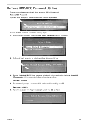
... 2 35 Execute the UnlockHD.EXE file to create the unlock code in DOS Mode using the format UnlockHD [Encode code] with details about removing HDD/BIOS password: Remove HDD Password: If you key in the password from the previous step to unlock the HDD as follows: UnlockHD 76943488 4. Remove HDD.../BIOS Password Utilities This section provides you with the code noted in the previous step, as shown. Key in the wrong HDD password three times, an ...
... 2 35 Execute the UnlockHD.EXE file to create the unlock code in DOS Mode using the format UnlockHD [Encode code] with details about removing HDD/BIOS password: Remove HDD Password: If you key in the password from the previous step to unlock the HDD as follows: UnlockHD 76943488 4. Remove HDD.../BIOS Password Utilities This section provides you with the code noted in the previous step, as shown. Key in the wrong HDD password three times, an ...
Service Guide
Page 46
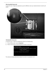
Press 1 or 2 to short the J1 jumper. The onscreen message determines whether the function is successful or not. 36 Chapter 2 Removing BIOS Passwords: To clear the User or Supervisor passwords, open the RAM door and use a metal instrument to clean the desired password shown on the screen. From a DOS prompt, execute clnpwd.exe 2. Cleaning BIOS Passwords To clean the User or Supervisor passwords, perform the following steps: 1.
Press 1 or 2 to short the J1 jumper. The onscreen message determines whether the function is successful or not. 36 Chapter 2 Removing BIOS Passwords: To clear the User or Supervisor passwords, open the RAM door and use a metal instrument to clean the desired password shown on the screen. From a DOS prompt, execute clnpwd.exe 2. Cleaning BIOS Passwords To clean the User or Supervisor passwords, perform the following steps: 1.

Service Guide
Page 47
Select the desired boot sequence by entering the corresponding sequence. For example, enter BS2 to change the boot sequence to display the usage screen. 3. Chapter 2 37 Execute BS.exe to HDD | CD ROM | LAN | Floppy. Using Boot Sequence Selector The Boot Sequence Selector allows the boot order to be changed without accessing the BIOS. Enter into DOS. 2. To use Boot Sequence Selector, perform the following steps: 1.
Select the desired boot sequence by entering the corresponding sequence. For example, enter BS2 to change the boot sequence to display the usage screen. 3. Chapter 2 37 Execute BS.exe to HDD | CD ROM | LAN | Floppy. Using Boot Sequence Selector The Boot Sequence Selector allows the boot order to be changed without accessing the BIOS. Enter into DOS. 2. To use Boot Sequence Selector, perform the following steps: 1.
Service Guide
Page 48
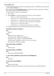
...(Type1, Offset08h): xxxxxxxx-xxxx-xxxx-xxxx-xxxxxxxxxxxx Asset Tag (Type3, Offset04h): Acet Asstag Write Product Name to EEPROM Input: dmitools /wp Acer Write Serial Number to EEPROM Input: dmitools /ws 01234567890123456789 4 ). Read DMI Information from Intel WFM20.pdf ) Input: dmitools /wu ... perform the following examples show the commands and the corresponding output information. Using DMITools The DMI (Desktop Management Interface) Tool copies BIOS information to EEPROM to make the new DMI data effective. 38 Chapter 2 The following messages report to screen to confirm completion...
...(Type1, Offset08h): xxxxxxxx-xxxx-xxxx-xxxx-xxxxxxxxxxxx Asset Tag (Type3, Offset04h): Acet Asstag Write Product Name to EEPROM Input: dmitools /wp Acer Write Serial Number to EEPROM Input: dmitools /ws 01234567890123456789 4 ). Read DMI Information from Intel WFM20.pdf ) Input: dmitools /wu ... perform the following examples show the commands and the corresponding output information. Using DMITools The DMI (Desktop Management Interface) Tool copies BIOS information to EEPROM to make the new DMI data effective. 38 Chapter 2 The following messages report to screen to confirm completion...

Service Guide
Page 51
Copy the PAWF5x64.fd file to flash the BIOS. Plug in AC power. Using the crisis disk 1. Press Fn +esc keys and hold them down, then plug in the USB Flash Disk without AC plug. 2. Press power button and the system will enter crisis mode to the USB flash disk root directory. 4. NOTE: Do not place any other *.fd files to the USB flash disk root directory. Chapter 2 41 The power button flashes orange. 3.
Copy the PAWF5x64.fd file to flash the BIOS. Plug in AC power. Using the crisis disk 1. Press Fn +esc keys and hold them down, then plug in the USB Flash Disk without AC plug. 2. Press power button and the system will enter crisis mode to the USB flash disk root directory. 4. NOTE: Do not place any other *.fd files to the USB flash disk root directory. Chapter 2 41 The power button flashes orange. 3.


