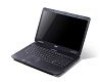
Service Guide
Page 7
... System Specifications 1 Features 1 Optical Media Drive 2 System Block Diagram 5 Your Acer Notebook tour 6 Front View 6 Closed Front View 7 Left View 7 Right ...Utility 32 WinFlash Utility 34 Remove HDD/BIOS Password Utilities 35 Machine Disassembly and Replacement 43 Disassembly Requirements 43 Pre-disassembly Instructions 44 Disassembly Process 44 External Module Disassembly Process ...45 External Modules Disassembly Flowchart 45 Removing the Battery Pack 46 Removing the SD Dummy Card 47 Removing the Lower Covers 48 Removing ...
... System Specifications 1 Features 1 Optical Media Drive 2 System Block Diagram 5 Your Acer Notebook tour 6 Front View 6 Closed Front View 7 Left View 7 Right ...Utility 32 WinFlash Utility 34 Remove HDD/BIOS Password Utilities 35 Machine Disassembly and Replacement 43 Disassembly Requirements 43 Pre-disassembly Instructions 44 Disassembly Process 44 External Module Disassembly Process ...45 External Modules Disassembly Flowchart 45 Removing the Battery Pack 46 Removing the SD Dummy Card 47 Removing the Lower Covers 48 Removing ...
Service Guide
Page 8
... Power Board 103 Replacing the Upper Cover 105 Replacing the LCD Module 109 Replacing the Keyboard 114 Replacing the Switch Cover 115 Replacing the Hard Disk Drive Module 115 Replacing the WLAN Module 117 Replacing the DIMM Modules 119 Replacing the ODD Module 119 Replacing the Lower Covers 120 Replacing the SD Dummy Card 120 Replacing the Battery 121 Troubleshooting 123 Common...
... Power Board 103 Replacing the Upper Cover 105 Replacing the LCD Module 109 Replacing the Keyboard 114 Replacing the Switch Cover 115 Replacing the Hard Disk Drive Module 115 Replacing the WLAN Module 117 Replacing the DIMM Modules 119 Replacing the ODD Module 119 Replacing the Lower Covers 120 Replacing the SD Dummy Card 120 Replacing the Battery 121 Troubleshooting 123 Common...
Service Guide
Page 54
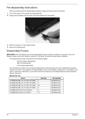
... unit disassembly • LCD module disassembly The flowcharts provided in the succeeding disassembly sections illustrate the entire disassembly sequence. Remove the battery pack. Observe the order of the sequence to avoid damage to any part of the LCD Module is divided into the following ...off the power to remove the mainboard, you must be disassembled outside of the hardware components. Disassembly Process IMPORTANT: The LCD Module cannot be replaced. Main Screw List Screw Quantity Part Number SCREW M2.48D 4.0L K 5.5D 0.8T ZKNL 1 86.NAF02.001 SCREW M2.48D 6.0L...
... unit disassembly • LCD module disassembly The flowcharts provided in the succeeding disassembly sections illustrate the entire disassembly sequence. Remove the battery pack. Observe the order of the sequence to avoid damage to any part of the LCD Module is divided into the following ...off the power to remove the mainboard, you must be disassembled outside of the hardware components. Disassembly Process IMPORTANT: The LCD Module cannot be replaced. Main Screw List Screw Quantity Part Number SCREW M2.48D 4.0L K 5.5D 0.8T ZKNL 1 86.NAF02.001 SCREW M2.48D 6.0L...
Service Guide
Page 85
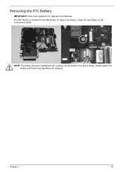
Please detach the battery and follow local regulations for disposal of all batteries. Chapter 3 75 Removing the RTC Battery IMPORTANT:Follow local regulations for disposal. To replace the battery, solder the new battery to the Mainboard. The RTC Battery is soldered to the connections shown. NOTE: The battery has been highlighted with a yellow oval as shown in the above image.
Please detach the battery and follow local regulations for disposal of all batteries. Chapter 3 75 Removing the RTC Battery IMPORTANT:Follow local regulations for disposal. To replace the battery, solder the new battery to the Mainboard. The RTC Battery is soldered to the connections shown. NOTE: The battery has been highlighted with a yellow oval as shown in the above image.
Service Guide
Page 131
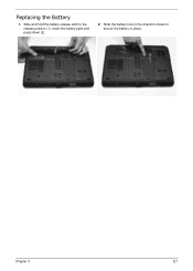
Slide and hold the battery release latch to secure the battery in place. 2 1 Chapter 3 121 Slide the battery lock in the direction shown to the release position (1), insert the battery pack and press down (2). 2. Replacing the Battery 1.
Slide and hold the battery release latch to secure the battery in place. 2 1 Chapter 3 121 Slide the battery lock in the direction shown to the release position (1), insert the battery pack and press down (2). 2. Replacing the Battery 1.
Service Guide
Page 135
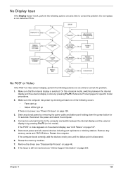
...following actions one until the failure point is discovered. 6. On this model). Make sure the computer has power by removing the power cable and battery and holding down the power button for specific model procedures. 2. Restart the computer. Make sure that the internal display is done by one ...add the devices one by pressing Fn+F5. Reseat the memory modules. 7. Remove the drives (see "Online Support Information" on page 233. Do not replace a non-defective FRUs: No POST or Video If the POST or video doesn't display, perform the following occurs: • Fans start up • ...
...following actions one until the failure point is discovered. 6. On this model). Make sure the computer has power by removing the power cable and battery and holding down the power button for specific model procedures. 2. Restart the computer. Make sure that the internal display is done by one ...add the devices one by pressing Fn+F5. Reseat the memory modules. 7. Remove the drives (see "Online Support Information" on page 233. Do not replace a non-defective FRUs: No POST or Video If the POST or video doesn't display, perform the following occurs: • Fans start up • ...
Service Guide
Page 136
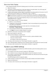
... software to determine that the computer is still not resolved, see "Online Support Information" on battery alone as this may be defective and should be replaced. NOTE: Ensure that : • The device is faulty and should be replaced. Minimize or close all Windows. If the Issue is not running on page 233. 126... "Disassembly Process" on the desktop and select Personalize´ Display Settings. Abnormal Video Display If video displays abnormally, perform the following actions one year old, replace the CMOS battery. 2. Reboot the computer. 2.
... software to determine that the computer is still not resolved, see "Online Support Information" on battery alone as this may be defective and should be replaced. NOTE: Ensure that : • The device is faulty and should be replaced. Minimize or close all Windows. If the Issue is not running on page 233. 126... "Disassembly Process" on the desktop and select Personalize´ Display Settings. Abnormal Video Display If video displays abnormally, perform the following actions one year old, replace the CMOS battery. 2. Reboot the computer. 2.
Service Guide
Page 145
... mouse uses a wireless connection, insert new batteries and confirm there is listed under Other Devices. 13. Restart the computer. 6. Restore system and file settings from a known good date using System Restore. Roll back the mouse driver to check the events log for errors. Do not replace a non-defective FRUs: 1. See the mouse...
... mouse uses a wireless connection, insert new batteries and confirm there is listed under Other Devices. 13. Restart the computer. 6. Restore system and file settings from a known good date using System Restore. Roll back the mouse driver to check the events log for errors. Do not replace a non-defective FRUs: 1. See the mouse...
Service Guide
Page 146
... circuit is suspected, or whether the system is detected, replace the FRU. NOTE: Verify that have nothing to isolate the failing FRU (do the following devices: • Non-Acer devices • Printer, mouse, and other external devices • Battery pack • Hard disk drive • DIMM •...; CD-ROM/Diskette drive Module • PC Cards 4. Follow these procedures to do not replace any FRU. 3. If the problem does...
... circuit is suspected, or whether the system is detected, replace the FRU. NOTE: Verify that have nothing to isolate the failing FRU (do the following devices: • Non-Acer devices • Printer, mouse, and other external devices • Battery pack • Hard disk drive • DIMM •...; CD-ROM/Diskette drive Module • PC Cards 4. Follow these procedures to do not replace any FRU. 3. If the problem does...
Service Guide
Page 245
... Utility 31 Antennas Removing 87 Replacing 90 B Battery Replacing 121 Battery Pack Removing 46 BIOS ROM... type 16 vendor 16 Version 16 BIOS Utility 23-31 Advanced 26 Boot 29 Exit 30 Navigating 23 Onboard Device Configuration 27 Power 29 Save and Exit 30 Security 26 System Security 30 Board Layout Top View 145 brightness hotkeys 14 C Camera Module Removing 82 Replacing... F Features 1 Flash Utility 31 FPC Cable Removing 85 FRU (Field Replaceable Unit) List 151 H Hard Disk Drive Removing 55 Replacing 115 HDTV Switch Failure 135 Hibernation mode hotkey 14 Hot Keys 12 I...
... Utility 31 Antennas Removing 87 Replacing 90 B Battery Replacing 121 Battery Pack Removing 46 BIOS ROM... type 16 vendor 16 Version 16 BIOS Utility 23-31 Advanced 26 Boot 29 Exit 30 Navigating 23 Onboard Device Configuration 27 Power 29 Save and Exit 30 Security 26 System Security 30 Board Layout Top View 145 brightness hotkeys 14 C Camera Module Removing 82 Replacing... F Features 1 Flash Utility 31 FPC Cable Removing 85 FRU (Field Replaceable Unit) List 151 H Hard Disk Drive Removing 55 Replacing 115 HDTV Switch Failure 135 Hibernation mode hotkey 14 Hot Keys 12 I...
Service Guide
Page 246
... Support Information 233 Optical Disk Drive Replacing 119 Optical Drive Module Removing 49 P Panel 6 Bottom 9 PC Card 10 Power Board Removing 69 Replacing 103 Power On Failure 124 R Replacing 103 RTC Battery Removing 75 S SD Dummy Card Removing 47 Replacing 120 Speakers 103 Removing 70 speakers ...hotkey 14 Switch Cover Removing 57 Replacing 115 System Block Diagram 5 T Test Compatible Components 219...
... Support Information 233 Optical Disk Drive Replacing 119 Optical Drive Module Removing 49 P Panel 6 Bottom 9 PC Card 10 Power Board Removing 69 Replacing 103 Power On Failure 124 R Replacing 103 RTC Battery Removing 75 S SD Dummy Card Removing 47 Replacing 120 Speakers 103 Removing 70 speakers ...hotkey 14 Switch Cover Removing 57 Replacing 115 System Block Diagram 5 T Test Compatible Components 219...


