Quick Start Guide
Page 7
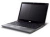
... (LCD), displays computer output (configuration may vary by model). Speakers Left and right speakers deliver stereo audio output. Charging: The light shows amber when the battery is closed up when Num Lock is activated. button Programmable key User-programmable. (only for certain models) 1. Fully charged: The light shows blue when in... which functions like the and right) left and right buttons function like a computer mouse. 8 Power indicator1 Indicates the computer's power status. 9 10 11 12 13 P Battery indicator1 Indicates the computer...
... (LCD), displays computer output (configuration may vary by model). Speakers Left and right speakers deliver stereo audio output. Charging: The light shows amber when the battery is closed up when Num Lock is activated. button Programmable key User-programmable. (only for certain models) 1. Fully charged: The light shows blue when in... which functions like the and right) left and right buttons function like a computer mouse. 8 Power indicator1 Indicates the computer's power status. 9 10 11 12 13 P Battery indicator1 Indicates the computer...

Quick Start Guide
Page 11
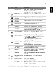
Memory compartment Houses the computer's main memory. Ventilation slots and cooling fan Battery release latch Enable the computer to stay cool, even after prolonged use. Releases the battery for removal. English 9 Base view 1 2 6 5 3 4 # Icon 1 2 3 4 5 6 Item Battery bay Battery lock Description Houses the computer's battery pack. Note: Do not cover or obstruct the opening of the fan. Hard disk bay Houses the computer's hard disk (secured with screws). Locks the battery in position.
Memory compartment Houses the computer's main memory. Ventilation slots and cooling fan Battery release latch Enable the computer to stay cool, even after prolonged use. Releases the battery for removal. English 9 Base view 1 2 6 5 3 4 # Icon 1 2 3 4 5 6 Item Battery bay Battery lock Description Houses the computer's battery pack. Note: Do not cover or obstruct the opening of the fan. Hard disk bay Houses the computer's hard disk (secured with screws). Locks the battery in position.
Service Guide
Page 7
... of Contents System Specifications 1 Features 1 System Block Diagram 6 Your Acer Notebook tour 7 Front View 7 Closed Front View 9 Left View ... Specifications and Configurations 17 System Utilities 23 BIOS Setup Utility 23 Navigating the BIOS Utility 23 Aspire 4745 BIOS 24 Information 24 Main 25 Security 26 Boot 29 Exit 30 BIOS Flash Utilities ...Instructions 42 Disassembly Process 42 External Module Disassembly Process 43 External Modules Disassembly Flowchart 43 Removing the Battery Pack 44 Removing the SD dummy card 45 Removing the Lower Cover 46 Removing the Optical ...
... of Contents System Specifications 1 Features 1 System Block Diagram 6 Your Acer Notebook tour 7 Front View 7 Closed Front View 9 Left View ... Specifications and Configurations 17 System Utilities 23 BIOS Setup Utility 23 Navigating the BIOS Utility 23 Aspire 4745 BIOS 24 Information 24 Main 25 Security 26 Boot 29 Exit 30 BIOS Flash Utilities ...Instructions 42 Disassembly Process 42 External Module Disassembly Process 43 External Modules Disassembly Flowchart 43 Removing the Battery Pack 44 Removing the SD dummy card 45 Removing the Lower Cover 46 Removing the Optical ...

Service Guide
Page 8
...Main Module Reassembly Procedure 87 Replacing the DC-In Cable 87 Replacing the LCD Module 88 Replacing the Right Speaker 88 Replacing the RTC Battery 89 Replacing the CPU 90 Replacing the Thermal Module 90 Replacing the Mainboard 91 Replacing the Bluetooth Module 94 Replacing the USB Board ... 103 Replacing the DIMM Modules 103 Replacing the ODD Module 104 Replacing the Lower Covers 105 Replacing the Dummy Cards 106 Replacing the Battery Pack 106 Troubleshooting 107 Common Problems 107 Power On Issue 108 No Display Issue 109 Random Loss of BIOS Settings 110 LCD Failure ...
...Main Module Reassembly Procedure 87 Replacing the DC-In Cable 87 Replacing the LCD Module 88 Replacing the Right Speaker 88 Replacing the RTC Battery 89 Replacing the CPU 90 Replacing the Thermal Module 90 Replacing the Mainboard 91 Replacing the Bluetooth Module 94 Replacing the USB Board ... 103 Replacing the DIMM Modules 103 Replacing the ODD Module 104 Replacing the Lower Covers 105 Replacing the Dummy Cards 106 Replacing the Battery Pack 106 Troubleshooting 107 Common Problems 107 Power On Issue 108 No Display Issue 109 Random Loss of BIOS Settings 110 LCD Failure ...

Service Guide
Page 13
... x 2.32 x 1.22 inches) • 390 g (0.86 lbs.)12 with 180 cm DC cable • Acer QuickCharge™ technology13:· • 80% charge in 1 hour· • 2-hour rapid charge system-off • 48.8 W 4400 mAh 6-cell Li-ion standard battery pack • Estimated battery life: Up to 6 hours13 • ENERGY STAR® Chapter 1 3
... x 2.32 x 1.22 inches) • 390 g (0.86 lbs.)12 with 180 cm DC cable • Acer QuickCharge™ technology13:· • 80% charge in 1 hour· • 2-hour rapid charge system-off • 48.8 W 4400 mAh 6-cell Li-ion standard battery pack • Estimated battery life: Up to 6 hours13 • ENERGY STAR® Chapter 1 3
Service Guide
Page 15
...8482; Deluxe· • NTI Media Maker™ • Gaming· • Oberon GameZone Acer Edition1 · • WildTangent® Acer Edition1 • Communication and ISP· • Microsoft® Silverlight™· • Windows...Acer Accessory Store • Acer Assist· • Acer Identity Card· • Acer Registration· • Acer Updater· • eBay® shortcut 2009· • Netflix shortcut1 Optional Items • Acer Media Center remote control • 1 GB / 2 GB / 4 GB DDR3 1066 MHz soDIMM module • 9-cell Li-ion battery...
...8482; Deluxe· • NTI Media Maker™ • Gaming· • Oberon GameZone Acer Edition1 · • WildTangent® Acer Edition1 • Communication and ISP· • Microsoft® Silverlight™· • Windows...Acer Accessory Store • Acer Assist· • Acer Identity Card· • Acer Registration· • Acer Updater· • eBay® shortcut 2009· • Netflix shortcut1 Optional Items • Acer Media Center remote control • 1 GB / 2 GB / 4 GB DDR3 1066 MHz soDIMM module • 9-cell Li-ion battery...
Service Guide
Page 18
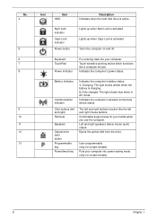
...Touch-sensitive pointing device which functions like the left and right mouse buttons. Charging: The light shows amber when the battery is activated. The left and right) Palmrest Speakers Optical drive eject button Programmable key PowerSmart key Indicates the computer... support area for certain models) 8 Chapter 1 Ejects the optical disk from the drive. Lights up when Caps Lock is active. Battery Indicator Communication indicator Click buttons (left and right buttons function like a computer mouse. Indicates the computer's wireless connectivity device status. Left...
...Touch-sensitive pointing device which functions like the left and right mouse buttons. Charging: The light shows amber when the battery is activated. The left and right) Palmrest Speakers Optical drive eject button Programmable key PowerSmart key Indicates the computer... support area for certain models) 8 Chapter 1 Ejects the optical disk from the drive. Lights up when Caps Lock is active. Battery Indicator Communication indicator Click buttons (left and right buttons function like a computer mouse. Indicates the computer's wireless connectivity device status. Left...

Service Guide
Page 21
... 1 11 Indicators The computer has several easy-to stay cool, even after prolonged use. Note: Do not cover or obstruct the fan opening. Releases the battery for removal. Icon Function Power Description Indicates the computer's power status. Bottom View 1 2 6 5 3 4 No. 1 2 3 4 5 6 Icon Item...
... 1 11 Indicators The computer has several easy-to stay cool, even after prolonged use. Note: Do not cover or obstruct the fan opening. Releases the battery for removal. Icon Function Power Description Indicates the computer's power status. Bottom View 1 2 6 5 3 4 No. 1 2 3 4 5 6 Icon Item...

Service Guide
Page 22
Indicates when the hard disk drive is charging. 2. Fully charged: The light shows green when in AC mode. Charging: The light shows amber when the battery is active. NOTE: 1. Communication indicator Indicates the computer's wireless connectivity device status. 12 Chapter 1 Icon Function Battery HDD Description Indicates the computer's battery status.
Indicates when the hard disk drive is charging. 2. Fully charged: The light shows green when in AC mode. Charging: The light shows amber when the battery is active. NOTE: 1. Communication indicator Indicates the computer's wireless connectivity device status. 12 Chapter 1 Icon Function Battery HDD Description Indicates the computer's battery status.

Service Guide
Page 32
... & model name Battery Type Pack capacity Normal Voltage Package configuration Specification 6 Cell SANYO/SONY/PANASONIC/SAMSUNG/SIMPLO AS2009A Li-ion 4400 mAh 2.2 Ah 3S2P LCD Item Vendor/model ...
... & model name Battery Type Pack capacity Normal Voltage Package configuration Specification 6 Cell SANYO/SONY/PANASONIC/SAMSUNG/SIMPLO AS2009A Li-ion 4400 mAh 2.2 Ah 3S2P LCD Item Vendor/model ...
Service Guide
Page 41
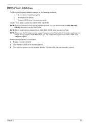
... BIOS flash, you use the Flash utility. Copy the flash utilities to update the system BIOS flash ROM. NOTE: Please use the Flash. If the battery pack does not contain enough power to run the Flash utility. Then boot the system from the bootable diskette. Prepare a bootable diskette. 2. The flash utility...
... BIOS flash, you use the Flash utility. Copy the flash utilities to update the system BIOS flash ROM. NOTE: Please use the Flash. If the battery pack does not contain enough power to run the Flash utility. Then boot the system from the bootable diskette. Prepare a bootable diskette. 2. The flash utility...

Service Guide
Page 52
Remove the battery pack. General Information Pre-disassembly Instructions Before proceeding with the disassembly procedure, make sure that order. Disassembly Process The disassembly process is divided into the ...
Remove the battery pack. General Information Pre-disassembly Instructions Before proceeding with the disassembly procedure, make sure that order. Disassembly Process The disassembly process is divided into the ...

Service Guide
Page 53
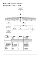
....PSR07.003 86.PSR07.003 86.N1407.007 Chapter 3 43 External Module Disassembly Process IMPORTANT:The outside housing and color may vary from system Remove Battery Remove Dummy Card Remove Lower Covers Screw List Step ODD Module ODD Bracket WLAN Module HDD Carrier Remove HDD . Turn off system and peripherals power...
....PSR07.003 86.PSR07.003 86.N1407.007 Chapter 3 43 External Module Disassembly Process IMPORTANT:The outside housing and color may vary from system Remove Battery Remove Dummy Card Remove Lower Covers Screw List Step ODD Module ODD Bracket WLAN Module HDD Carrier Remove HDD . Turn off system and peripherals power...

Service Guide
Page 54
Removing the Battery Pack 1. Slide the battery lock in the direction shown. 2. Slide and hold the battery release latch to the release position (1), then lift out the battery pack from the main unit (2). 2 1 Please detach the battery and follow local regulations for disposal. 44 Chapter 3 Turn computer over.
Removing the Battery Pack 1. Slide the battery lock in the direction shown. 2. Slide and hold the battery release latch to the release position (1), then lift out the battery pack from the main unit (2). 2 1 Please detach the battery and follow local regulations for disposal. 44 Chapter 3 Turn computer over.

Service Guide
Page 56
Removing the Lower Cover 1. Loosen the five (5) captive screws from the lower cover. 3. Remove the lower cover as shown. 46 Chapter 3 See "Removing the Battery Pack" on page 44. 2.
Removing the Lower Cover 1. Loosen the five (5) captive screws from the lower cover. 3. Remove the lower cover as shown. 46 Chapter 3 See "Removing the Battery Pack" on page 44. 2.
Service Guide
Page 62
... Touch Pad Bracket Remove CRT Cable Remove main board Remove LCD module Remove Right Speaker Module Remove DC cable Remove wifi switch board Remove RTC Battery Remove thermal module Remove CPU Screw List Step LCD Module Upper Cover L.
... Touch Pad Bracket Remove CRT Cable Remove main board Remove LCD module Remove Right Speaker Module Remove DC cable Remove wifi switch board Remove RTC Battery Remove thermal module Remove CPU Screw List Step LCD Module Upper Cover L.

Service Guide
Page 63
Chapter 3 53 Step Keyboard (red callout) Size M2.5*6.5 Quantity 9 Screw Type Keyboard M2.5*4L 2 (green callout) Keyboard 3 (blue callout) 3. There are five (5) securing clips that you only use your fingers to remove the keyboard. It is recommended that must be released in order to remove the Keyboard. 1. Remove the 14 securing screws from the lower cover. See "Removing the Battery Pack" on page 44. 2. Turn the computer over and fully open the lid. Removing the Keyboard CAUTION: Using tools to remove the Keyboard may cause damage to the outer casing.
Chapter 3 53 Step Keyboard (red callout) Size M2.5*6.5 Quantity 9 Screw Type Keyboard M2.5*4L 2 (green callout) Keyboard 3 (blue callout) 3. There are five (5) securing clips that you only use your fingers to remove the keyboard. It is recommended that must be released in order to remove the Keyboard. 1. Remove the 14 securing screws from the lower cover. See "Removing the Battery Pack" on page 44. 2. Turn the computer over and fully open the lid. Removing the Keyboard CAUTION: Using tools to remove the Keyboard may cause damage to the outer casing.

Service Guide
Page 80
Removing the RTC Battery 1. Please detach the RTC battery and follow local regulations for disposal. Pry the RTC battery from the guides on page 65. 2. Turn the computer over. Thread Wifi antennas and disengage from the mainboard. See "Removing the Mainboard" on the bottom cover. 3. Removing the WiFi Antenna Cable 1. Disengage the WiFi antennas from the guides on page 65. 2. See "Removing the Mainboard" on the chassis. 70 Chapter 3
Removing the RTC Battery 1. Please detach the RTC battery and follow local regulations for disposal. Pry the RTC battery from the guides on page 65. 2. Turn the computer over. Thread Wifi antennas and disengage from the mainboard. See "Removing the Mainboard" on the bottom cover. 3. Removing the WiFi Antenna Cable 1. Disengage the WiFi antennas from the guides on page 65. 2. See "Removing the Mainboard" on the chassis. 70 Chapter 3

Service Guide
Page 99
Replace the right speaker cable in place. 3. Chapter 3 89 Replacing the RTC Battery 1. Snap the RTC battery into it's socket as shown. 2. Replace the two (2) screws to secure the right speaker in to the chassis as shown.
Replace the right speaker cable in place. 3. Chapter 3 89 Replacing the RTC Battery 1. Snap the RTC battery into it's socket as shown. 2. Replace the two (2) screws to secure the right speaker in to the chassis as shown.

Service Guide
Page 116
Replacing the Battery Pack 1. Insert the battery pack and press down. 2. Replacing the Dummy Cards 1. Insert the SD Dummy Card into the slot and push until the card clicks into place and is flush with the casing. Slide the battery lock in the direction shown to secure the battery in place. 106 Chapter 3
Replacing the Battery Pack 1. Insert the battery pack and press down. 2. Replacing the Dummy Cards 1. Insert the SD Dummy Card into the slot and push until the card clicks into place and is flush with the casing. Slide the battery lock in the direction shown to secure the battery in place. 106 Chapter 3


