Quick Start Guide
Page 5
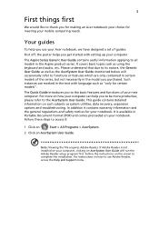
... certain models of the series, but not necessarily in the text with setting up your computer. Note: Viewing the file requires Adobe Reader. For instructions on how to use your Acer notebook, we have designed a set of your new computer. It covers basic topics such as system utilities, data recovery, expansion options and troubleshooting. For more productive, please refer to the AcerSystem User Guide. It is not installed...
... certain models of the series, but not necessarily in the text with setting up your computer. Note: Viewing the file requires Adobe Reader. For instructions on how to use your Acer notebook, we have designed a set of your new computer. It covers basic topics such as system utilities, data recovery, expansion options and troubleshooting. For more productive, please refer to the AcerSystem User Guide. It is not installed...
Quick Start Guide
Page 7
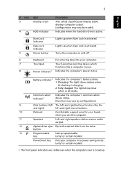
... activated. 5 Power button Turns the computer on and off. 6 Keyboard For entering data into power-saving mode. (only for your computer. 7 Touchpad Touch-sensitive pointing device which functions like the and right) left and right buttons function like a computer mouse. 8 Power indicator1 Indicates the computer's power status. 9 10 11 12 13 P Battery indicator1 Indicates the computer's battery status. 1. Indicates when the hard disk drive is charging. 2. Communication indicator1 Indicates the computer's communication device status. (Function may vary by configuration...
... activated. 5 Power button Turns the computer on and off. 6 Keyboard For entering data into power-saving mode. (only for your computer. 7 Touchpad Touch-sensitive pointing device which functions like the and right) left and right buttons function like a computer mouse. 8 Power indicator1 Indicates the computer's power status. 9 10 11 12 13 P Battery indicator1 Indicates the computer's battery status. 1. Indicates when the hard disk drive is charging. 2. Communication indicator1 Indicates the computer's communication device status. (Function may vary by configuration...
Quick Start Guide
Page 10
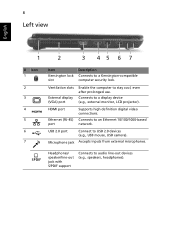
.../ speaker/line-out jack with S/PDIF support Connects to stay cool, even after prolonged use. HDMI port Ethernet (RJ-45) port Supports high definition digital video connections. Connects to a Kensington-compatible computer security lock. 8 Left view English 1 2 3 45 6 7 # Icon 1 2 3 4 5 6 7 Item Kensington lock slot Description Connects to an Ethernet 10/100/1000-based network. Microphone jack Accepts inputs from external microphones. USB 2.0 port Connect to a display device (e.g., external monitor, LCD projector). Connects to USB 2.0 devices (e.g., USB mouse, USB camera).
.../ speaker/line-out jack with S/PDIF support Connects to stay cool, even after prolonged use. HDMI port Ethernet (RJ-45) port Supports high definition digital video connections. Connects to a Kensington-compatible computer security lock. 8 Left view English 1 2 3 45 6 7 # Icon 1 2 3 4 5 6 7 Item Kensington lock slot Description Connects to an Ethernet 10/100/1000-based network. Microphone jack Accepts inputs from external microphones. USB 2.0 port Connect to a display device (e.g., external monitor, LCD projector). Connects to USB 2.0 devices (e.g., USB mouse, USB camera).
Service Guide
Page 7
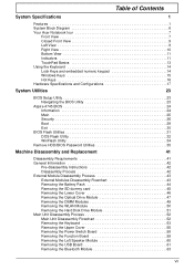
... Acer Notebook tour 7 Front View 7 Closed Front View 9 Left View 9 Right View 10 Bottom View 11 Indicators 11 TouchPad Basics 13 Using the Keyboard 14 Lock Keys and embedded numeric keypad 14 Windows Keys 15 Hot Keys 16 Hardware Specifications and Configurations 17 System Utilities 23 BIOS Setup Utility 23 Navigating the BIOS Utility 23 Aspire 4745 BIOS 24 Information 24 Main 25 Security 26 Boot 29 Exit 30 BIOS Flash Utilities 31 DOS Flash Utility 32 WinFlash Utility 34 Remove HDD/BIOS Password Utilities...
... Acer Notebook tour 7 Front View 7 Closed Front View 9 Left View 9 Right View 10 Bottom View 11 Indicators 11 TouchPad Basics 13 Using the Keyboard 14 Lock Keys and embedded numeric keypad 14 Windows Keys 15 Hot Keys 16 Hardware Specifications and Configurations 17 System Utilities 23 BIOS Setup Utility 23 Navigating the BIOS Utility 23 Aspire 4745 BIOS 24 Information 24 Main 25 Security 26 Boot 29 Exit 30 BIOS Flash Utilities 31 DOS Flash Utility 32 WinFlash Utility 34 Remove HDD/BIOS Password Utilities...

Service Guide
Page 8
... USB Board 95 Replacing the TouchPad Bracket 95 Replacing the Left Speaker Module 96 Replacing the Function Board 97 Replacing the Power Switch Board 97 Replacing the Upper Cover 98 Replacing the Keyboard 101 Replacing the Hard Disk Drive Module 101 Replacing the WLAN Board 103 Replacing the DIMM Modules 103 Replacing the ODD Module 104 Replacing the Lower Covers 105 Replacing the Dummy Cards 106 Replacing the Battery Pack 106 Troubleshooting 107 Common Problems 107 Power On Issue 108 No Display Issue 109 Random Loss of BIOS Settings 110 LCD...
... USB Board 95 Replacing the TouchPad Bracket 95 Replacing the Left Speaker Module 96 Replacing the Function Board 97 Replacing the Power Switch Board 97 Replacing the Upper Cover 98 Replacing the Keyboard 101 Replacing the Hard Disk Drive Module 101 Replacing the WLAN Board 103 Replacing the DIMM Modules 103 Replacing the ODD Module 104 Replacing the Lower Covers 105 Replacing the Dummy Cards 106 Replacing the Battery Pack 106 Troubleshooting 107 Common Problems 107 Power On Issue 108 No Display Issue 109 Random Loss of BIOS Settings 110 LCD...
Service Guide
Page 18
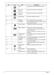
...11 12 13 Icon Item HDD Num Lock indicator Caps Lock indicator Power button Description Indicates when the hard disk drive is activated. Keyboard TouchPad Power Indicator For entering data into your computer into power-saving mode. (only for certain models) 8 Chapter 1 Battery Indicator Communication indicator Click buttons (left and right mouse buttons. Indicates the computer's wireless connectivity device status. The left and right buttons function like a computer mouse. Lights up when Num Lock is charging. 2. Touch-sensitive pointing device which functions like the left and...
...11 12 13 Icon Item HDD Num Lock indicator Caps Lock indicator Power button Description Indicates when the hard disk drive is activated. Keyboard TouchPad Power Indicator For entering data into your computer into power-saving mode. (only for certain models) 8 Chapter 1 Battery Indicator Communication indicator Click buttons (left and right mouse buttons. Indicates the computer's wireless connectivity device status. The left and right buttons function like a computer mouse. Lights up when Num Lock is charging. 2. Touch-sensitive pointing device which functions like the left and...
Service Guide
Page 19
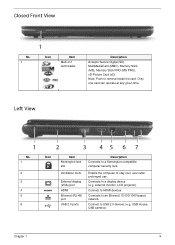
...) port USB 2.0 ports Description Connects to stay cool, even after prolonged use. Only one card can operate at any given time. Enable the computer to a Kensington-compatible computer security lock. Connect to remove/install the card. external monitor, LCD projector). Chapter 1 9 Note: Push to USB 2.0 devices (e.g. Connect to HDMI devices Connects to a display device (e.g. USB mouse, USB camera). Closed Front View No. 1 1 Icon Item Multi-in-1 card reader Description Accepts Secure Digital (SD), MultiMediaCard (MMC), Memory Stick (MS), Memory Stick PRO (MS PRO), xD...
...) port USB 2.0 ports Description Connects to stay cool, even after prolonged use. Only one card can operate at any given time. Enable the computer to a Kensington-compatible computer security lock. Connect to remove/install the card. external monitor, LCD projector). Chapter 1 9 Note: Push to USB 2.0 devices (e.g. Connect to HDMI devices Connects to a display device (e.g. USB mouse, USB camera). Closed Front View No. 1 1 Icon Item Multi-in-1 card reader Description Accepts Secure Digital (SD), MultiMediaCard (MMC), Memory Stick (MS), Memory Stick PRO (MS PRO), xD...
Service Guide
Page 26
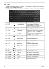
... display screen, external monitor (if connected) and both. Turns the speakers on or off to return. Turns the embedded numeric keypad on and off . Decreases the sound volume. Return to the next media file. 16 Chapter 1 Hot Keys The computer employs hotkeys or key combinations to access most of the computer's controls like screen brightness, volume output and the BIOS utility. Increases the screen brightness. Stop playing the selected media file. Decreases the screen brightness. Turns the internal touchpad...
... display screen, external monitor (if connected) and both. Turns the speakers on or off to return. Turns the embedded numeric keypad on and off . Decreases the sound volume. Return to the next media file. 16 Chapter 1 Hot Keys The computer employs hotkeys or key combinations to access most of the computer's controls like screen brightness, volume output and the BIOS utility. Increases the screen brightness. Stop playing the selected media file. Decreases the screen brightness. Turns the internal touchpad...
Service Guide
Page 34
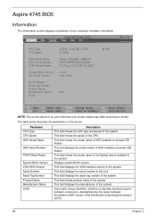
... serial number of this screen. This field displays the asset tag number of this system. This field displays the manufacturer of the system. This field shows the model name of the Optical device installed in software construction, standardized by the Open Software Foundation (OSF) as part of the Distributed Computing Environment (DCE). 24 Chapter 2 Parameter CPU Type CPU Speed HDD Model Name HDD Serial Number ATAPI Model Name System BIOS Version VGA BIOS Version Serial Number...
... serial number of this screen. This field displays the asset tag number of this system. This field displays the manufacturer of the system. This field shows the model name of the Optical device installed in software construction, standardized by the Open Software Foundation (OSF) as part of the Distributed Computing Environment (DCE). 24 Chapter 2 Parameter CPU Type CPU Speed HDD Model Name HDD Serial Number ATAPI Model Name System BIOS Version VGA BIOS Version Serial Number...
Service Guide
Page 36
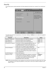
... was used to reset it. 26 Chapter 2 InsydeH20 Setup Utility Information Main Security Power Boot Exit Supervisor Password Is: Clear User Password Is: Clear IDE0 Password Is: Clear Set Supervisor Password Set User Password Set IDE0 Password Rev. 3.5 Item Specific Help Install or Change the password and the length of the hard disk password. Parameter Supervisor Password Is User Password Is HDD Password Is Set Supervisor Password Set User Password Set HDD Password Password on Boot [Disabled] F1 Help ESC Exit Select Item F5/F6 Change Values F9 Setup Default Select Menu Enter...
... was used to reset it. 26 Chapter 2 InsydeH20 Setup Utility Information Main Security Power Boot Exit Supervisor Password Is: Clear User Password Is: Clear IDE0 Password Is: Clear Set Supervisor Password Set User Password Set IDE0 Password Rev. 3.5 Item Specific Help Install or Change the password and the length of the hard disk password. Parameter Supervisor Password Is User Password Is HDD Password Is Set Supervisor Password Set User Password Set HDD Password Password on Boot [Disabled] F1 Help ESC Exit Select Item F5/F6 Change Values F9 Setup Default Select Menu Enter...
Service Guide
Page 37
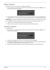
... Enter New Password and Confirm New Password fields. Use the ↑ and ↓ keys to "Clear". 4. The computer then sets the Supervisor Password parameter to highlight the Set Supervisor Password parameter and press the Enter key. Chapter 2 27 Press Enter. If desired, you have changed the settings, press u to save the changes and exit the BIOS Setup Utility. Removing a Password Follow these steps as you are done, press F10 to enable the Password on the screen...
... Enter New Password and Confirm New Password fields. Use the ↑ and ↓ keys to "Clear". 4. The computer then sets the Supervisor Password parameter to highlight the Set Supervisor Password parameter and press the Enter key. Chapter 2 27 Press Enter. If desired, you have changed the settings, press u to save the changes and exit the BIOS Setup Utility. Removing a Password Follow these steps as you are done, press F10 to enable the Password on the screen...
Service Guide
Page 38
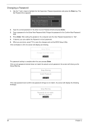
... match. Press Enter. If the current password entered does not match the actual current password, the screen will show you are done, press F10 to save the changes and exit the BIOS Setup Utility. Set Supervisor Password Enter Current Password [ ] Enter New Password [ ] Confirm New Password [ ] 2. Type a password in the Enter New Password field. When you the Setup Warning. The Set Password box appears. If desired, you can enable the Password on boot parameter. 6. Use the ↑ and ↓ keys to "Set". 5.
... match. Press Enter. If the current password entered does not match the actual current password, the screen will show you are done, press F10 to save the changes and exit the BIOS Setup Utility. Set Supervisor Password Enter Current Password [ ] Enter New Password [ ] Confirm New Password [ ] 2. Type a password in the Enter New Password field. When you the Setup Warning. The Set Password box appears. If desired, you can enable the Password on boot parameter. 6. Use the ↑ and ↓ keys to "Set". 5.
Service Guide
Page 40
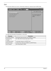
... screen allows you to CMOS. Information Main InsydeH20 Setup Utility Security Power Boot Exit Rev. 3.5 Exit Saving Changes Exit Discarding Changes Load Setup Defaults Discard Changes Save Changes Item Specific Help Exit System Setup and save your changes to CMOS. F1 Help ESC Exit Select Item F5/F6 Change Values F9 Setup Default Select Menu Enter Select SubMenu F10 Save and Exit The table below describes the parameters in this screen. Exit utility...
... screen allows you to CMOS. Information Main InsydeH20 Setup Utility Security Power Boot Exit Rev. 3.5 Exit Saving Changes Exit Discarding Changes Load Setup Defaults Discard Changes Save Changes Item Specific Help Exit System Setup and save your changes to CMOS. F1 Help ESC Exit Select Item F5/F6 Change Values F9 Setup Default Select Menu Enter Select SubMenu F10 Save and Exit The table below describes the parameters in this screen. Exit utility...
Service Guide
Page 62
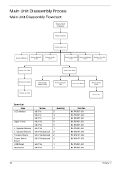
...001 86.W4107.002 86.W4107.002 86.W4107.002 86.PSR07.001 86.PSR07.001 52 Chapter 3 Main Unit Disassembly Process Main Unit Disassembly Flowchart Remove external modules before proceeding Remove keyboard Remove upper cover Remove USB Board Remove Bluetooth Module Remove Function Board Remove Power Switch Remove Left Speaker Board Module Remove Touch Pad Bracket Remove CRT Cable Remove main board Remove LCD module Remove Right Speaker Module Remove DC cable Remove wifi switch board Remove RTC Battery Remove thermal module Remove CPU Screw List Step LCD Module Upper Cover L.
...001 86.W4107.002 86.W4107.002 86.W4107.002 86.PSR07.001 86.PSR07.001 52 Chapter 3 Main Unit Disassembly Process Main Unit Disassembly Flowchart Remove external modules before proceeding Remove keyboard Remove upper cover Remove USB Board Remove Bluetooth Module Remove Function Board Remove Power Switch Remove Left Speaker Board Module Remove Touch Pad Bracket Remove CRT Cable Remove main board Remove LCD module Remove Right Speaker Module Remove DC cable Remove wifi switch board Remove RTC Battery Remove thermal module Remove CPU Screw List Step LCD Module Upper Cover L.
Service Guide
Page 117
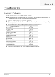
Use the following procedure as possible. 2. Verify the symptoms by attempting to re-create the failure by running the diagnostic test or by repeating the same operation. 3. Symptoms (Verified) Go To Power On Issue Page 108 No Display Issue Page 109 LCD Failure Page 111 Internal Keyboard Failure Page 111 TouchPad Failure Page 112 Internal Speaker Failure Page 112 ODD Failure...
Use the following procedure as possible. 2. Verify the symptoms by attempting to re-create the failure by running the diagnostic test or by repeating the same operation. 3. Symptoms (Verified) Go To Power On Issue Page 108 No Display Issue Page 109 LCD Failure Page 111 Internal Keyboard Failure Page 111 TouchPad Failure Page 112 Internal Speaker Failure Page 112 ODD Failure...

Service Guide
Page 119
... Connect an external monitor to the computer and switch between the internal display and the external display is selected. Restart the computer. Remove the drives (see "LCD Failure" on page 167. Remove any stored power by pressing Fn+F5. If the computer boots correctly, add the devices one by checking at a time to correct the problem. Reseat the memory modules. 7. If the POST or video appears on the external display, see "Disassembly...
... Connect an external monitor to the computer and switch between the internal display and the external display is selected. Restart the computer. Remove the drives (see "LCD Failure" on page 167. Remove any stored power by pressing Fn+F5. If the computer boots correctly, add the devices one by checking at a time to correct the problem. Reseat the memory modules. 7. If the POST or video appears on the external display, see "Disassembly...
Service Guide
Page 120
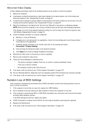
... reconnect the power and data cables between devices. Click and drag the Resolution slider to determine that the computer is more than one year old, replace the CMOS battery. 2. d. If the computer is properly installed. Check the Device Manager to the desired resolution. Replace the Motherboard. 6. See "Disassembly Process" on page 42. 4. Run the Windows Memory Diagnostic from the BIOS, the drive may reduce display brightness. Random Loss...
... reconnect the power and data cables between devices. Click and drag the Resolution slider to determine that the computer is more than one year old, replace the CMOS battery. 2. d. If the computer is properly installed. Check the Device Manager to the desired resolution. Replace the Motherboard. 6. See "Disassembly Process" on page 42. 4. Run the Windows Memory Diagnostic from the BIOS, the drive may reduce display brightness. Random Loss...
Service Guide
Page 124
... locate and resolve issues with the computer. c. Select Repair your computer. Select Startup Repair. If an issue is virus free. 3. For more information see Windows Help and Support. 10. Ensure all external devices. 2. Run a complete virus scan using System Restore. Select the appropriate operating system, and click Next. h. Run the Windows 7 Startup Repair Utility: a. When prompted, press any recently added hardware and associated software. 8. d. e. Remove any key to start to enter the BIOS Utility. Replace...
... locate and resolve issues with the computer. c. Select Repair your computer. Select Startup Repair. If an issue is virus free. 3. For more information see Windows Help and Support. 10. Ensure all external devices. 2. Run a complete virus scan using System Restore. Select the appropriate operating system, and click Next. h. Run the Windows 7 Startup Repair Utility: a. When prompted, press any recently added hardware and associated software. 8. d. e. Remove any key to start to enter the BIOS Utility. Replace...
Service Guide
Page 127
.... Check that the drive is identical to the ODD. Reseat the drive ensuring and all cables are connected correctly. 5. c. Try an alternate cable, if available. d. Test the drive using other ATA Devices shown if applicable. Turn off the power and remove the cover to inspect the connections to one at a time to correct the problem. 1. b. Turn off the power and remove the cover to inspect the connections to enter the BIOS Utility. 2. b.
.... Check that the drive is identical to the ODD. Reseat the drive ensuring and all cables are connected correctly. 5. c. Try an alternate cable, if available. d. Test the drive using other ATA Devices shown if applicable. Turn off the power and remove the cover to inspect the connections to one at a time to correct the problem. 1. b. Turn off the power and remove the cover to inspect the connections to enter the BIOS Utility. 2. b.
Service Guide
Page 129
..., LAN Port, external MIC or Speakers, PCI Express Card, 5-in-1 Card Reader or Volume Wheel fail, perform the following actions one at a time to determine that: • The device is properly installed. Try an alternative mouse. 2. If the mouse uses a USB connection, try an alternate USB port. 4. Remove any recently added software and reboot. 8. Run the Event Viewer to correct the problem. Check the Device Manager to correct the problem. 1. Remove any recently added hardware...
..., LAN Port, external MIC or Speakers, PCI Express Card, 5-in-1 Card Reader or Volume Wheel fail, perform the following actions one at a time to determine that: • The device is properly installed. Try an alternative mouse. 2. If the mouse uses a USB connection, try an alternate USB port. 4. Remove any recently added software and reboot. 8. Run the Event Viewer to correct the problem. Check the Device Manager to correct the problem. 1. Remove any recently added hardware...


