Aspire 3000 / 3500 / 5000 Service Guide
Page 7
Table of Contents Chapter 1 System Introduction 1 Features 1 System Block Diagram (For Aspire 3000/5000 3 System Block Diagram (For Aspire 3500 4 Board Layout (For Aspire 3000/5000 5 Top View 5 Bottom View 6 Panel 8 Front view 8 Closed front view 9 Left view 9 Right view 10 Rear view 10 Bottom view 11 ...Disc Drive Module 51 Removing the Memory 51 Removing the LCD Module 53 Removing the Middle Cover 53 Removing the Keyboard 53 Removing the Fan, the CPU Thermal Module and the CPU 53 Removing the Wireless LAN Card 54 Removing the LCD Module 55 Disassembling the LCD Module ...
Table of Contents Chapter 1 System Introduction 1 Features 1 System Block Diagram (For Aspire 3000/5000 3 System Block Diagram (For Aspire 3500 4 Board Layout (For Aspire 3000/5000 5 Top View 5 Bottom View 6 Panel 8 Front view 8 Closed front view 9 Left view 9 Right view 10 Rear view 10 Bottom view 11 ...Disc Drive Module 51 Removing the Memory 51 Removing the LCD Module 53 Removing the Middle Cover 53 Removing the Keyboard 53 Removing the Fan, the CPU Thermal Module and the CPU 53 Removing the Wireless LAN Card 54 Removing the LCD Module 55 Disassembling the LCD Module ...

Aspire 3000 / 3500 / 5000 Service Guide
Page 12
...Number BLOCK DIAGRAM Rev 3A Date: Wednesday, February 23, 2005 Sheet 1 of 26 6 5 4 3 2 1 Chapter 1 3 System Block Diagram (For Aspire 3000/5000) 8 7 HOST 200MHz ZCLK 133MHz CLK-GEN AGP 66MHz ICS 952801 PCI 33MHz D USB 48MHz REF 14.318MHz Page 2 3V_ALWAYS 5VPCU 3V_S5 3V/5V ...8 7 6 5 4 3 2 1 DDR SO-DIMM DDR 333 Page 5 CPU AMD Athlon64 SMT uPGA754 Page 3,4 HyperTransport 16x16 1600MT/s Thermal Thermal sensor & Fan NB INTA# SIS M760GX (698 PIN BGA) DVO LVDS Transmitter SIS302ELV Page 6,7,8 Page 9 RGB LVDS ZL5 Block Diagram D CRT 1x D-SUB 15-Pin Page 10...
...Number BLOCK DIAGRAM Rev 3A Date: Wednesday, February 23, 2005 Sheet 1 of 26 6 5 4 3 2 1 Chapter 1 3 System Block Diagram (For Aspire 3000/5000) 8 7 HOST 200MHz ZCLK 133MHz CLK-GEN AGP 66MHz ICS 952801 PCI 33MHz D USB 48MHz REF 14.318MHz Page 2 3V_ALWAYS 5VPCU 3V_S5 3V/5V ...8 7 6 5 4 3 2 1 DDR SO-DIMM DDR 333 Page 5 CPU AMD Athlon64 SMT uPGA754 Page 3,4 HyperTransport 16x16 1600MT/s Thermal Thermal sensor & Fan NB INTA# SIS M760GX (698 PIN BGA) DVO LVDS Transmitter SIS302ELV Page 6,7,8 Page 9 RGB LVDS ZL5 Block Diagram D CRT 1x D-SUB 15-Pin Page 10...

Aspire 3000 / 3500 / 5000 Service Guide
Page 20
...the battery to a Kensington-compatible computer security lock. Locks the battery in place. Note: Do not cover or obstruct the opening of the fan. Security keylock Connects to remove the battery pack. Houses the computer's battery pack. Bottom view # 1 2 3 4 5 6 Item ...Hard disc bay Battery release latch Battery bay Battery lock Cooling fan Memory comparment Description Houses the computer's hard disc (secured by a screw). House the computer's main memory. Chapter 1 11 External display port Connects ...
...the battery to a Kensington-compatible computer security lock. Locks the battery in place. Note: Do not cover or obstruct the opening of the fan. Security keylock Connects to remove the battery pack. Houses the computer's battery pack. Bottom view # 1 2 3 4 5 6 Item ...Hard disc bay Battery release latch Battery bay Battery lock Cooling fan Memory comparment Description Houses the computer's hard disc (secured by a screw). House the computer's main memory. Chapter 1 11 External display port Connects ...

Aspire 3000 / 3500 / 5000 Service Guide
Page 62
...Battery" on page 50. 2. See "Removing the Keyboard" on page 50. 2. Disconnect the fan cable. 6. Open the notebook as shown. 5. Removing the Keyboard 1. Remove the three screws securing the system fan. 5. See "Removing the Battery" on page 53. 4. Disconnect the keyboard cable then remove the... keyboard. Then detach the fan from the main unit. 53 Chapter 3 Detach the middle cover carefully then ...
...Battery" on page 50. 2. See "Removing the Keyboard" on page 50. 2. Disconnect the fan cable. 6. Open the notebook as shown. 5. Removing the Keyboard 1. Remove the three screws securing the system fan. 5. See "Removing the Battery" on page 53. 4. Disconnect the keyboard cable then remove the... keyboard. Then detach the fan from the main unit. 53 Chapter 3 Detach the middle cover carefully then ...

Aspire 3000 / 3500 / 5000 Service Guide
Page 65
... "Removing the LCD Module" on page 53. 5. Remove the four screws securing the right LCD bracket, then remove the right bracket. 17. See "Removing the Fan, the CPU Thermal Module and the CPU" on page 55. 7. Remove the four screws securing the LCD bezel. 9. Remove the four screws securing the left...
... "Removing the LCD Module" on page 53. 5. Remove the four screws securing the right LCD bracket, then remove the right bracket. 17. See "Removing the Fan, the CPU Thermal Module and the CPU" on page 55. 7. Remove the four screws securing the LCD bezel. 9. Remove the four screws securing the left...
Aspire 3000 / 5000 User's Guide
Page 13
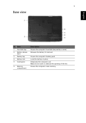
5 Base view English # Item 1 Hard disk bay 2 Battery release latch 3 Battery bay 4 Battery lock 5 Cooling fan 6 Memory compartment Description Houses the computer's hard disk (secured by a screw). Helps keep the computer cool. Releases the battery for removal. Note: Do not cover or obstruct the opening of the fan. Houses the computer's main memory. Locks the battery in place. Houses the computer's battery pack.
5 Base view English # Item 1 Hard disk bay 2 Battery release latch 3 Battery bay 4 Battery lock 5 Cooling fan 6 Memory compartment Description Houses the computer's hard disk (secured by a screw). Helps keep the computer cool. Releases the battery for removal. Note: Do not cover or obstruct the opening of the fan. Houses the computer's main memory. Locks the battery in place. Houses the computer's battery pack.


