
Acer Aspire 1710 Service Guide
Page 7
... BIOS Flash Utility 44 Chapter 3 Machine Disassembly and Replacement 46 General Information 47 Before You Begin 47 Disassembly Procedure Flowchart 48 Disassembling 51 Remove the battery 51 Remove the HDD module 51 Remove the combo drive 51 Remove the thermal module 52 Remove CPU 52 Remove the memory 52 Remove VGA...
... BIOS Flash Utility 44 Chapter 3 Machine Disassembly and Replacement 46 General Information 47 Before You Begin 47 Disassembly Procedure Flowchart 48 Disassembling 51 Remove the battery 51 Remove the HDD module 51 Remove the combo drive 51 Remove the thermal module 52 Remove CPU 52 Remove the memory 52 Remove VGA...
Acer Aspire 1710 Service Guide
Page 13
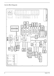
ICS952623 D PAGE : 12 VCCRTC VIN VA2 VAD Power RTC PAGE : 22 BATTERY & ACIN PAGE : 28 5V_HDD 12V_HDD & 5V_HDD C HUB I M M PAGE 15 2 3*CPU/CPU1*SDRAM 5*3V66 3*PCIF 7*PCI 2*REF 2*48MHz 1*SRC/SRC# 1 Main CLOCK GEN. System Block Diagram 4 8 7 ... MDC Slot RJ11 PAGE 19 USB0 Card Reader Connector 4 3 A Size Document Number Custom BLOCK DIAGRAM Date: Saturday, November 29, 2003 Sheet 2 2 of 1 Rev 1A 34 Aspire 1710
ICS952623 D PAGE : 12 VCCRTC VIN VA2 VAD Power RTC PAGE : 22 BATTERY & ACIN PAGE : 28 5V_HDD 12V_HDD & 5V_HDD C HUB I M M PAGE 15 2 3*CPU/CPU1*SDRAM 5*3V66 3*PCIF 7*PCI 2*REF 2*48MHz 1*SRC/SRC# 1 Main CLOCK GEN. System Block Diagram 4 8 7 ... MDC Slot RJ11 PAGE 19 USB0 Card Reader Connector 4 3 A Size Document Number Custom BLOCK DIAGRAM Date: Saturday, November 29, 2003 Sheet 2 2 of 1 Rev 1A 34 Aspire 1710

Acer Aspire 1710 Service Guide
Page 22
Chapter 1 13 Enhances the audio quality Enable the computer to stay cool, even after prolonged use. Bottom Panel # 1 2 3 Item Battery cover Sub-woofer Ventilation slots Description Protects the battery bay.
Chapter 1 13 Enhances the audio quality Enable the computer to stay cool, even after prolonged use. Bottom Panel # 1 2 3 Item Battery cover Sub-woofer Ventilation slots Description Protects the battery bay.
Acer Aspire 1710 Service Guide
Page 23
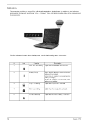
Off--the AC adapter is not connected, or the battery is not installed. 3 Caps Lock Activity Lights when Caps Lock is activated. 4 Num Lock Activity Lights when Numeric Lock is activated. 5 Scroll Lock Activity Lights ... Description 1 Hard Disk Drive Activity Lights when the hard disk drive is active. 2 Battery Charge Green--the AC adapter is connected and the battery is fully charged. Amber--the AC adapter is connected and the battery is activated. 14 Aspire 1710 The five indicators located above the keyboard, in addition to two indicators positioned at...
Off--the AC adapter is not connected, or the battery is not installed. 3 Caps Lock Activity Lights when Caps Lock is activated. 4 Num Lock Activity Lights when Numeric Lock is activated. 5 Scroll Lock Activity Lights ... Description 1 Hard Disk Drive Activity Lights when the hard disk drive is active. 2 Battery Charge Green--the AC adapter is connected and the battery is fully charged. Amber--the AC adapter is connected and the battery is activated. 14 Aspire 1710 The five indicators located above the keyboard, in addition to two indicators positioned at...
Acer Aspire 1710 Service Guide
Page 37
... (mA) Output voltage Output voltage frequency (kHz) Output Current Ambit 10 ~ 20V 1A (max.) 725Vrms 40 ~ 65Hz 1.5 mArms ~ 3.75mArms Specification 28 Aspire 1710 key Yes Yes Battery Item Vendor & model name Battery Type Pack capacity Cell voltage Number of keypads Windows 95 keys Internal & external keyboard work simultaneously Specification NS LPC keyboard controller PC87591...
... (mA) Output voltage Output voltage frequency (kHz) Output Current Ambit 10 ~ 20V 1A (max.) 725Vrms 40 ~ 65Hz 1.5 mArms ~ 3.75mArms Specification 28 Aspire 1710 key Yes Yes Battery Item Vendor & model name Battery Type Pack capacity Cell voltage Number of keypads Windows 95 keys Internal & external keyboard work simultaneously Specification NS LPC keyboard controller PC87591...

Acer Aspire 1710 Service Guide
Page 53
... NOTE: If you do not have a crisis recovery diskette at hand, then you should create a Crisis Recovery Diskette before you use the Phlash. If the battery pack does not contain enough power to update the system BIOS flash ROM. Copy the Phlash utilities to run the Phlash utility. Fellow the steps...
... NOTE: If you do not have a crisis recovery diskette at hand, then you should create a Crisis Recovery Diskette before you use the Phlash. If the battery pack does not contain enough power to update the system BIOS flash ROM. Copy the Phlash utilities to run the Phlash utility. Fellow the steps...

Acer Aspire 1710 Service Guide
Page 57
Start x7 (fix on base cover) Base Cover Dx4 Cx1 Battery Dommy Cover Battery Cx2 MDC Modem Card Memory Cx1 Optical Drive Module (Please see next page) Cx4 VGA Card (AGP Card) Disconnect subwoofer cable Cx2 x2 Cx4 Subwoofer ...
Start x7 (fix on base cover) Base Cover Dx4 Cx1 Battery Dommy Cover Battery Cx2 MDC Modem Card Memory Cx1 Optical Drive Module (Please see next page) Cx4 VGA Card (AGP Card) Disconnect subwoofer cable Cx2 x2 Cx4 Subwoofer ...

Acer Aspire 1710 Service Guide
Page 60
Remove the battery or dummy battery module. Remove the combo drive 1. Detach the Combo drive. 51 Aspire 1710 Disassembling Remove the battery 1. Release the seven screws as shown here. 4. Remove the bottom shield plate. 3. Remove the HDD module 1. Remove the 5 screws as shown here. 2. Remove the one screw as shown here. 2. Lift the HDD module and detach the IDE connector and power connector at the same time. Remove the 4 screws that secure the HDD module. 2.
Remove the battery or dummy battery module. Remove the combo drive 1. Detach the Combo drive. 51 Aspire 1710 Disassembling Remove the battery 1. Release the seven screws as shown here. 4. Remove the bottom shield plate. 3. Remove the HDD module 1. Remove the 5 screws as shown here. 2. Remove the one screw as shown here. 2. Lift the HDD module and detach the IDE connector and power connector at the same time. Remove the 4 screws that secure the HDD module. 2.

Acer Aspire 1710 Service Guide
Page 79
...Power System Check To verify the symptom of the problem, power on page 72. Disconnect the power adapter and install the charged battery pack; T "Check the Battery Pack" on the computer using each of these devices do not work, reconnect the cable connector and repeat the failing operation. ...Memory check Memory errors might stop system operations, show error messages on page 71. NOTE: Make sure that power is supplied by the battery pack. then check that the DIMM is supplied. 3. A loose connection can cause an error. If any of the following list: T "Check ...
...Power System Check To verify the symptom of the problem, power on page 72. Disconnect the power adapter and install the charged battery pack; T "Check the Battery Pack" on the computer using each of these devices do not work, reconnect the cable connector and repeat the failing operation. ...Memory check Memory errors might stop system operations, show error messages on page 71. NOTE: Make sure that power is supplied by the battery pack. then check that the DIMM is supplied. 3. A loose connection can cause an error. If any of the following list: T "Check ...

Acer Aspire 1710 Service Guide
Page 80
.... 2. T If the problem is not correct, go to +20.5V Pin 2: 0V, Ground 1. T If the voltage is not corrected, see "Check the Battery Pack" on page 72. 71 Aspire 1710 If the power-on page 81. See the following : T Replace the System board. If the operational charge does not work, see "Undetermined Problems...
.... 2. T If the problem is not correct, go to +20.5V Pin 2: 0V, Ground 1. T If the voltage is not corrected, see "Check the Battery Pack" on page 72. 71 Aspire 1710 If the power-on page 81. See the following : T Replace the System board. If the operational charge does not work, see "Undetermined Problems...

Acer Aspire 1710 Service Guide
Page 81
...indicator still does not light up , replace the DC/DC charger board. If the charge indicator still does not light up , replace the battery pack. Touchpad Check If the touchpad doesn't work, do the following actions one at a time to correct the problem. This symptom is still... less than 50% of time. Remove the battery pack and measure the voltage between battery terminals 1(+) and 6(ground). If the battery status indicator does not light up, remove the battery pack and let it return to the touchpad pointer. Do not replace a non-...
...indicator still does not light up , replace the DC/DC charger board. If the charge indicator still does not light up , replace the battery pack. Touchpad Check If the touchpad doesn't work, do the following actions one at a time to correct the problem. This symptom is still... less than 50% of time. Remove the battery pack and measure the voltage between battery terminals 1(+) and 6(ground). If the battery status indicator does not light up, remove the battery pack and let it return to the touchpad pointer. Do not replace a non-...
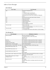
Acer Aspire 1710 Service Guide
Page 83
...Message List Error Messages FRU/Action in BIOS Setup Utility. Keyboard error see "Keyboard or Auxiliary Input Device Check" on page 69. Battery critical LOW In this situation BIOS will shut down system, no message will be shown before "Equipment Configuration Error") Memory Error at ...offset: nnnn DIMM System board System battery is specified. CPU BIOS Update Code Mismatch 2. Unlock key switch Unlock external keyboard Monitor type does not match CMOS - Thermal critical...
...Message List Error Messages FRU/Action in BIOS Setup Utility. Keyboard error see "Keyboard or Auxiliary Input Device Check" on page 69. Battery critical LOW In this situation BIOS will shut down system, no message will be shown before "Equipment Configuration Error") Memory Error at ...offset: nnnn DIMM System board System battery is specified. CPU BIOS Update Code Mismatch 2. Unlock key switch Unlock external keyboard Monitor type does not match CMOS - Thermal critical...
Acer Aspire 1710 Service Guide
Page 84
... the drive is defined with the proper diskette type in BIOS Setup Utility See "External Diskette Drive Check" on page 69. RTC battery System board Failing Bits: nnnn DIMM BIOS ROM System board Fixed Disk n None Invalid System Configuration Data BIOS ROM System board I/O ... Run "Load Default Settings" in BIOS Setup Utility. RTC battery System board Memory size found Enter Setup and see if fixed disk and drive A: are properly identified. Diskette drive Hard disk drive System board 75 Aspire 1710 System board Previous boot incomplete - Cache disabled System board CPU...
... the drive is defined with the proper diskette type in BIOS Setup Utility See "External Diskette Drive Check" on page 69. RTC battery System board Failing Bits: nnnn DIMM BIOS ROM System board Fixed Disk n None Invalid System Configuration Data BIOS ROM System board I/O ... Run "Load Default Settings" in BIOS Setup Utility. RTC battery System board Memory size found Enter Setup and see if fixed disk and drive A: are properly identified. Diskette drive Hard disk drive System board 75 Aspire 1710 System board Previous boot incomplete - Cache disabled System board CPU...

Acer Aspire 1710 Service Guide
Page 85
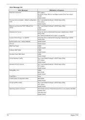
... on page 70. System board No beep during POST. See "Power System Check" on and LCD is blank. Power source (battery pack and power adapter). Reconnect the DIMM. Power source (battery pack and power adapter). Speaker System board Chapter 4 76 Reconnect the LCD connectors. Ensure every connector is connected tightly and correctly...
... on page 70. System board No beep during POST. See "Power System Check" on and LCD is blank. Power source (battery pack and power adapter). Reconnect the DIMM. Power source (battery pack and power adapter). Speaker System board Chapter 4 76 Reconnect the LCD connectors. Ensure every connector is connected tightly and correctly...

Acer Aspire 1710 Service Guide
Page 86
... Unreadable LCD screen Missing pels in Sequence Enter BIOS Utility to -FRU Error Message LCD-Related Symptoms Symptom / Error LCD backlight doesn't work ). Battery pack System board 77 Aspire 1710 Index of Symptom-to execute "Load Setup Default Settings", then reboot system. Action in characters Abnormal screen Wrong color displayed LCD has extra...
... Unreadable LCD screen Missing pels in Sequence Enter BIOS Utility to -FRU Error Message LCD-Related Symptoms Symptom / Error LCD backlight doesn't work ). Battery pack System board 77 Aspire 1710 Index of Symptom-to execute "Load Setup Default Settings", then reboot system. Action in characters Abnormal screen Wrong color displayed LCD has extra...
Acer Aspire 1710 Service Guide
Page 87
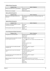
...disk drive System board The system doesn't enter standby mode after opening the LCD. See "Hibernation Mode" on page 30. Remove battery pack and let it cool for 2 hours. Press Fn+oand see if the computer enters hibernation mode. LCD cover switch System ...board Chapter 4 78 DIMM System board Speaker-Related Symptoms Symptom / Error In Windows, multimedia programs, no sound. Refresh battery (continue use battery until power off, then charge battery). PCMCIA-Related Symptoms Symptom / Error System cannot detect the PC Card (PCMCIA) PCMCIA slot pin is from actual ...
...disk drive System board The system doesn't enter standby mode after opening the LCD. See "Hibernation Mode" on page 30. Remove battery pack and let it cool for 2 hours. Press Fn+oand see if the computer enters hibernation mode. LCD cover switch System ...board Chapter 4 78 DIMM System board Speaker-Related Symptoms Symptom / Error In Windows, multimedia programs, no sound. Refresh battery (continue use battery until power off, then charge battery). PCMCIA-Related Symptoms Symptom / Error System cannot detect the PC Card (PCMCIA) PCMCIA slot pin is from actual ...
Acer Aspire 1710 Service Guide
Page 90
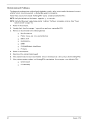
...supported by the computer. Determine if the problem has changed. 6. Do not replace a non-defective FRU: T System board T LCD assembly 81 Aspire 1710 If any problems are incorrect, whether a short circuit is suspected, or whether the system is operating correctly. (See "Power System Check" on...one at a time until you find the failing FRU. 7. If the problem remains, replace the following devices: T Non-Acer devices T Printer, mouse, and other external devices T Battery pack T Hard disk drive T DIMM T CD-ROM/Diskette drive Module T PC Cards 4. NOTE: Verify that the power...
...supported by the computer. Determine if the problem has changed. 6. Do not replace a non-defective FRU: T System board T LCD assembly 81 Aspire 1710 If any problems are incorrect, whether a short circuit is suspected, or whether the system is operating correctly. (See "Power System Check" on...one at a time until you find the failing FRU. 7. If the problem remains, replace the following devices: T Non-Acer devices T Printer, mouse, and other external devices T Battery pack T Hard disk drive T DIMM T CD-ROM/Diskette drive Module T PC Cards 4. NOTE: Verify that the power...
Acer Aspire 1710 Service Guide
Page 108
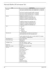
Microsoft Windows XP Environment Test Processor Item Memory LCD Hard Disk Drive DVD-ROM Drive 8X DVD/CD-RW Combo AC Adapter (3 pin) Power Cord Battery Li-Ion, 12 cells CRT Port Specifications Intel Pentium 4 Northwood 2.6GHZ 512K 400FSB SL6PP D-1 STEPPING Intel Pentium 4 Northwood 2.8GHZ 512K 533FSB SL6PF D-1 STEPPING Intel Prescott 2.... LISIMPL CRT Monitor: View Sonic PF775 Philips Brilliance 109P 19" Silicon Graphics 21" Dell Trinitron 21" ViewSonic GS790 ViewSonic GS773 Dell 2000FP LCD Monitor: LCD Acer AL722 LCD akia KX1 Projector: Panasonic PT-L757U Panasonic PT-L556EA 99...
Microsoft Windows XP Environment Test Processor Item Memory LCD Hard Disk Drive DVD-ROM Drive 8X DVD/CD-RW Combo AC Adapter (3 pin) Power Cord Battery Li-Ion, 12 cells CRT Port Specifications Intel Pentium 4 Northwood 2.6GHZ 512K 400FSB SL6PP D-1 STEPPING Intel Pentium 4 Northwood 2.8GHZ 512K 533FSB SL6PF D-1 STEPPING Intel Prescott 2.... LISIMPL CRT Monitor: View Sonic PF775 Philips Brilliance 109P 19" Silicon Graphics 21" Dell Trinitron 21" ViewSonic GS790 ViewSonic GS773 Dell 2000FP LCD Monitor: LCD Acer AL722 LCD akia KX1 Projector: Panasonic PT-L757U Panasonic PT-L556EA 99...
Acer Aspire 1710 Service Guide
Page 117
A AC Adapter 29 AFLASH Utility 44 Audio 22 B Battery 28 BIOS 22 package 22 ROM size 22 ROM type 22 vendor 22 Version 22 BIOS Setup Utility 32 BIOS Supports protocol 22 BIOS Utility ...
A AC Adapter 29 AFLASH Utility 44 Audio 22 B Battery 28 BIOS 22 package 22 ROM size 22 ROM type 22 vendor 22 Version 22 BIOS Setup Utility 32 BIOS Supports protocol 22 BIOS Utility ...

Acer Aspire 1710 Service Guide
Page 118
... Information 106 P Panel 7, 84 Bottom 13 right 10, 11 Parallel Port 27 PC Card 14, 28 PCMCIA 28 Power Management 30 Power System Check 70 Battery Pack 72 Power Adapter 71 R RTC 22 S Second Level Cache 22 speakers hotkey 18 Standby Mode 30 Super I/O 22 System Layout 5 System Check Procedures 69...
... Information 106 P Panel 7, 84 Bottom 13 right 10, 11 Parallel Port 27 PC Card 14, 28 PCMCIA 28 Power Management 30 Power System Check 70 Battery Pack 72 Power Adapter 71 R RTC 22 S Second Level Cache 22 speakers hotkey 18 Standby Mode 30 Super I/O 22 System Layout 5 System Check Procedures 69...


