
Acer Aspire 1710 Service Guide
Page 7
... Panel 13 Indicators 14 Keyboard 16 Special keys 16 Touchpad 20 Touchpad basics 20 Launch Keys 21 Hardware Specifications and Configurations 22 Chapter 2 System Utilities 32 BIOS Setup Utility 32 Navigating the BIOS Utility 33 Info 34 Main 35 Advanced 37 Security 38 Boot 42 Exit 43 BIOS Flash Utility 44 Chapter 3 Machine Disassembly and Replacement 46 General Information 47 Before You Begin 47 Disassembly Procedure Flowchart 48 Disassembling 51 Remove the battery 51 Remove the HDD module 51 Remove...
... Panel 13 Indicators 14 Keyboard 16 Special keys 16 Touchpad 20 Touchpad basics 20 Launch Keys 21 Hardware Specifications and Configurations 22 Chapter 2 System Utilities 32 BIOS Setup Utility 32 Navigating the BIOS Utility 33 Info 34 Main 35 Advanced 37 Security 38 Boot 42 Exit 43 BIOS Flash Utility 44 Chapter 3 Machine Disassembly and Replacement 46 General Information 47 Before You Begin 47 Disassembly Procedure Flowchart 48 Disassembling 51 Remove the battery 51 Remove the HDD module 51 Remove...

Acer Aspire 1710 Service Guide
Page 8
... Remove the LED board 59 Detach the front panel 60 Remove the Audio DJ board 61 Remove the touch pad 61 Remove the touch pad board 62 Remove the lid switch cable 62 Remove the floppy drive 62 Remove the speaker set 63 Remove the mainboard 64 Remove the system fan 64 FDD Module 65 HDD Module 66 Combo Module 66 Chapter 4 Troubleshooting 68 System Check Procedures 69 External Diskette Drive Check 69 External CD-ROM Drive Check 69 Keyboard or Auxiliary Input Device Check 69 Memory...
... Remove the LED board 59 Detach the front panel 60 Remove the Audio DJ board 61 Remove the touch pad 61 Remove the touch pad board 62 Remove the lid switch cable 62 Remove the floppy drive 62 Remove the speaker set 63 Remove the mainboard 64 Remove the system fan 64 FDD Module 65 HDD Module 66 Combo Module 66 Chapter 4 Troubleshooting 68 System Check Procedures 69 External Diskette Drive Check 69 External CD-ROM Drive Check 69 Keyboard or Auxiliary Input Device Check 69 Memory...
Acer Aspire 1710 Service Guide
Page 10
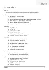
... Connectivity T Modem: Software Modem V.92 56Kbps (MDC) T 10/100/1000 Mbps Gigabit Ethernet LAN T Optional Mini-PCI 802.11g or 802.11 a/g T One switch to enable or disable wireless function T Keyboard and pointing device T Four universal serial but (UBS) ports 2.0 T Two IEEE 1394 ports T Bluetooth ready (manufacturing option) Expansion T T PC card slot enableing a range of add-on options Upgrageable CPU, hard disk and memory modules I/O Ports T T T T T One type II PC Card slot (PCMCIA and CardBus) One RJ-11 modem jack...
... Connectivity T Modem: Software Modem V.92 56Kbps (MDC) T 10/100/1000 Mbps Gigabit Ethernet LAN T Optional Mini-PCI 802.11g or 802.11 a/g T One switch to enable or disable wireless function T Keyboard and pointing device T Four universal serial but (UBS) ports 2.0 T Two IEEE 1394 ports T Bluetooth ready (manufacturing option) Expansion T T PC card slot enableing a range of add-on options Upgrageable CPU, hard disk and memory modules I/O Ports T T T T T One type II PC Card slot (PCMCIA and CardBus) One RJ-11 modem jack...
Acer Aspire 1710 Service Guide
Page 12
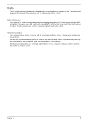
... Aspire 1710 series computer features an accelerated graphics port (AGP) video system with its multimedia capabilities, makes it ideally suited to manage a presentation on your computer, while your audience watches the monitor or projector screen. This provides a robust solution, while enabling high quality video output. Display The 17" display panel provides a large viewing area for maximum efficiency and ease-of-use the computer's LCD panel only, the external device...
... Aspire 1710 series computer features an accelerated graphics port (AGP) video system with its multimedia capabilities, makes it ideally suited to manage a presentation on your computer, while your audience watches the monitor or projector screen. This provides a robust solution, while enabling high quality video output. Display The 17" display panel provides a large viewing area for maximum efficiency and ease-of-use the computer's LCD panel only, the external device...
Acer Aspire 1710 Service Guide
Page 13
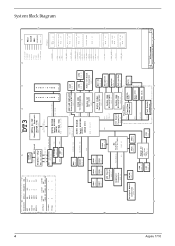
... VCCRTC VIN VA2 VAD Power RTC PAGE : 22 BATTERY & ACIN PAGE : 28 5V_HDD 12V_HDD & 5V_HDD C HUB I M M PAGE 15 2 3*CPU/CPU1*SDRAM 5*3V66 3*PCIF 7*PCI 2*REF 2*48MHz 1*SRC/SRC# 1 Main CLOCK GEN. System Block Diagram 4 8 7 PCI DEVICES IDSEL # REQ/GNT # IRQ AGP N/A N/A A, C LAN AD16 0 B Card bus AD17 1 C 1394 AD18 2 D MINI-PCI AD19 3 E,F D LCD Panel LCD ID2 LCD ID1 LCD ID0 SB SB SB...
... VCCRTC VIN VA2 VAD Power RTC PAGE : 22 BATTERY & ACIN PAGE : 28 5V_HDD 12V_HDD & 5V_HDD C HUB I M M PAGE 15 2 3*CPU/CPU1*SDRAM 5*3V66 3*PCIF 7*PCI 2*REF 2*48MHz 1*SRC/SRC# 1 Main CLOCK GEN. System Block Diagram 4 8 7 PCI DEVICES IDSEL # REQ/GNT # IRQ AGP N/A N/A A, C LAN AD16 0 B Card bus AD17 1 C 1394 AD18 2 D MINI-PCI AD19 3 E,F D LCD Panel LCD ID2 LCD ID1 LCD ID0 SB SB SB...
Acer Aspire 1710 Service Guide
Page 17
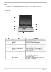
...provide the same functions as you to connect peripheral devices to your hands when typing on the keyboard. 1 switch button for wired/wireless LAN, or Bluetooth (optional) 1 e-mail launch button 1 launch button for Internet browser 2 programmable buttons Light emitting diodes (LEDs) that functions like a computer mouse. Turns the computer on and off. Buttons and indicators for inputing typed data. Full-size keyboard for the Audio DJ function. Front Panel # 1 2 3 4 5 6 7 8 9 Item Display Power button Keyboard Touchpad Click buttons & scroll key Audio DJ controls and indicator Palm rest...
...provide the same functions as you to connect peripheral devices to your hands when typing on the keyboard. 1 switch button for wired/wireless LAN, or Bluetooth (optional) 1 e-mail launch button 1 launch button for Internet browser 2 programmable buttons Light emitting diodes (LEDs) that functions like a computer mouse. Turns the computer on and off. Buttons and indicators for inputing typed data. Full-size keyboard for the Audio DJ function. Front Panel # 1 2 3 4 5 6 7 8 9 Item Display Power button Keyboard Touchpad Click buttons & scroll key Audio DJ controls and indicator Palm rest...
Acer Aspire 1710 Service Guide
Page 19
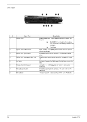
.../ Port Optical drive Optical disc read . Used to CD-Rs and CD-RWs. Locks and release the lid (one on the left). The slot supports a standard Type II PC card (PCMCIA). 10 Aspire 1710 Press the eject button to remove a disc from the PC card slot. T DVD Dual Light emitting diode (LED) that indicates when an optical disc is being read indicator Optical drive eject button Optical drive emergency eject hole Left latch Floppy drive/Card reader PC card...
.../ Port Optical drive Optical disc read . Used to CD-Rs and CD-RWs. Locks and release the lid (one on the left). The slot supports a standard Type II PC card (PCMCIA). 10 Aspire 1710 Press the eject button to remove a disc from the PC card slot. T DVD Dual Light emitting diode (LED) that indicates when an optical disc is being read indicator Optical drive eject button Optical drive emergency eject hole Left latch Floppy drive/Card reader PC card...
Acer Aspire 1710 Service Guide
Page 21
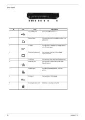
...video Connects to a PS2 mouse. PS2 port Connects to a television or display device with S-video input. Kensington lock slot Attaches a security connector. 12 Aspire 1710 COM port Network jack Connects to a phone line. External display port Connects an external (VGA) display devices monitor. Parallel port Connects a parallel device, such as a printer. Modem jack Connects the built-in fax/data modem to other serial interface devices. Connects to an Ethernet 10/100/1000based network. Rear Panel # 1 2 3 4 5 6 7 8 9 Icon Port Two USB ports Description Connects...
...video Connects to a PS2 mouse. PS2 port Connects to a television or display device with S-video input. Kensington lock slot Attaches a security connector. 12 Aspire 1710 COM port Network jack Connects to a phone line. External display port Connects an external (VGA) display devices monitor. Parallel port Connects a parallel device, such as a printer. Modem jack Connects the built-in fax/data modem to other serial interface devices. Connects to an Ethernet 10/100/1000based network. Rear Panel # 1 2 3 4 5 6 7 8 9 Icon Port Two USB ports Description Connects...
Acer Aspire 1710 Service Guide
Page 27
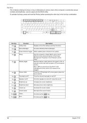
... use Ctrl+Alt+F1 Intel international hot key, when LCD monitor is hot plugged. Device Manager Accesses Windows Device Manager. Brightness down Decreases the sound volume. Home End Functions as the d key. 18 Aspire 1710 To activate hot keys, press and hold the Fn key before pressing the other key in the Windows Control Panel. Hot Key Fn+l Fn+m Fn-n Fn-o Fn-p Fn-q Fn-r Fn-s Fn-x Fn-¨z Fn-w Fn-y Fn-{ Fn-} Function Hotkey help Description Displays a list of the Power Management Properties in the hot key combination. Switches display...
... use Ctrl+Alt+F1 Intel international hot key, when LCD monitor is hot plugged. Device Manager Accesses Windows Device Manager. Brightness down Decreases the sound volume. Home End Functions as the d key. 18 Aspire 1710 To activate hot keys, press and hold the Fn key before pressing the other key in the Windows Control Panel. Hot Key Fn+l Fn+m Fn-n Fn-o Fn-p Fn-q Fn-r Fn-s Fn-x Fn-¨z Fn-w Fn-y Fn-{ Fn-} Function Hotkey help Description Displays a list of the Power Management Properties in the hot key combination. Switches display...
Acer Aspire 1710 Service Guide
Page 31
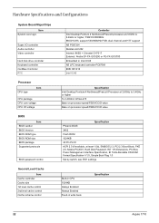
...Specification 22 Aspire 1710 Hardware Specifications and Configurations System Board MajorChips Item System core logic Super I/O controller Audio controller Video controller Hard disk drive controller Keyboard controller CardBus Controller RTC Processor CPU type Item CPU package CPU core voltage CPU I/O voltage BIOS Item BIOS vendor BIOS Version BIOS ROM type BIOS ROM size BIOS package Supported protocols BIOS password control Controller Intel Desktop Pentium 4 Northwood/Prescott processor at least 1.0b), SMBIOS 2.3, PCI 2.3 Boot Block, PXE 2.0, Mobile PC2001, Hard Disk Password...
...Specification 22 Aspire 1710 Hardware Specifications and Configurations System Board MajorChips Item System core logic Super I/O controller Audio controller Video controller Hard disk drive controller Keyboard controller CardBus Controller RTC Processor CPU type Item CPU package CPU core voltage CPU I/O voltage BIOS Item BIOS vendor BIOS Version BIOS ROM type BIOS ROM size BIOS package Supported protocols BIOS password control Controller Intel Desktop Pentium 4 Northwood/Prescott processor at least 1.0b), SMBIOS 2.3, PCI 2.3 Boot Block, PXE 2.0, Mobile PC2001, Hard Disk Password...

Acer Aspire 1710 Service Guide
Page 36
...) 1280x1024 (32 bit colors) 1600x1200 (32 bit colors) Video Memory Item Fixed or upgradeable Video memory size Specification Fixed, share the system memory 32MB Parallel Port Item Parallel port controller Number of parallel port Location Connector type Parallel port function control Supports ECP/EPP Optional ECP DMA channel (in BIOS Setup) Optional parallel port I/O address (in BIOS Setup) Optional parallel port IRQ (in BIOS Setup) Specification NS PC87391 1 Rear side 25-pin D-type Enable/Disable by BIOS Setup Yes (set by BIOS setup) DMA channel 1 and 3 378, 278, 3BC IRQ7...
...) 1280x1024 (32 bit colors) 1600x1200 (32 bit colors) Video Memory Item Fixed or upgradeable Video memory size Specification Fixed, share the system memory 32MB Parallel Port Item Parallel port controller Number of parallel port Location Connector type Parallel port function control Supports ECP/EPP Optional ECP DMA channel (in BIOS Setup) Optional parallel port I/O address (in BIOS Setup) Optional parallel port IRQ (in BIOS Setup) Specification NS PC87391 1 Rear side 25-pin D-type Enable/Disable by BIOS Setup Yes (set by BIOS setup) DMA channel 1 and 3 378, 278, 3BC IRQ7...

Acer Aspire 1710 Service Guide
Page 45
... display device is connected on external video port. Chapter 2 36 shows Summary Screen is not allowed to 640MB This field reports the memory size of the system. Enables, disables Boot Menu during POST. Parameter System Time System Date System Memory Extended Memory Video Memory Fast Boot Power on display will not be in order to save power when AC is set to disable or auto. Memory size is connected, the power on display LCD Auto Dim F12 Boot Menu Description Format/Option Sets...
... display device is connected on external video port. Chapter 2 36 shows Summary Screen is not allowed to 640MB This field reports the memory size of the system. Enables, disables Boot Menu during POST. Parameter System Time System Date System Memory Extended Memory Video Memory Fast Boot Power on display will not be in order to save power when AC is set to disable or auto. Memory size is connected, the power on display LCD Auto Dim F12 Boot Menu Description Format/Option Sets...
Acer Aspire 1710 Service Guide
Page 48
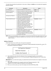
... "Enter New Password" field. Setting a Password Follow these steps as you have to return your notebook computer to your password, you may have three tries before the system halts. Defines whether a password is Set User Password Set Supervisor Password Primary Harddisk Security Password on HDD is written to save the changes and exit the BIOS Setup Utility. 39 Aspire 1710 The following sub-options are the default and suggested parameter settings. Use the w andy keys to HDD...
... "Enter New Password" field. Setting a Password Follow these steps as you have to return your notebook computer to your password, you may have three tries before the system halts. Defines whether a password is Set User Password Set Supervisor Password Primary Harddisk Security Password on HDD is written to save the changes and exit the BIOS Setup Utility. 39 Aspire 1710 The following sub-options are the default and suggested parameter settings. Use the w andy keys to HDD...

Acer Aspire 1710 Service Guide
Page 49
... password, the computer sets the User Password parameter to "Clear". 4. Type the current password in the Enter New Password field. The computer then sets the Supervisor Password parameter to "Set". 5. When you have changed the settings, press u to save the changes and exit the BIOS Setup Utility. Type a password in the Enter Current Password field and press e. 3. The password setting is OK, the screen will display as following. Chapter 2 40 If desired, you can enable the Password on boot parameter. 6. Removing a Password...
... password, the computer sets the User Password parameter to "Clear". 4. Type the current password in the Enter New Password field. The computer then sets the Supervisor Password parameter to "Set". 5. When you have changed the settings, press u to save the changes and exit the BIOS Setup Utility. Type a password in the Enter Current Password field and press e. 3. The password setting is OK, the screen will display as following. Chapter 2 40 If desired, you can enable the Password on boot parameter. 6. Removing a Password...
Acer Aspire 1710 Service Guide
Page 83
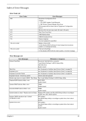
... of Error Messages Error Code List Error Codes 006 010 070 071 072 110 Error Messages Equipment Configuration Error Causes: 1. "Load Default Settings" in BIOS Setup Utility. Hard disk drive System board Stuck Key see "Keyboard or Auxiliary Input Device Check" on page 69. Keyboard locked - Battery critical LOW In this situation BIOS will show message. Unlock key switch Unlock external keyboard Monitor type does not match CMOS - Keyboard Controller Failed see "Keyboard or Auxiliary Input Device Check" on page 69. System timer error RTC battery Run BIOS Setup Utility to...
... of Error Messages Error Code List Error Codes 006 010 070 071 072 110 Error Messages Equipment Configuration Error Causes: 1. "Load Default Settings" in BIOS Setup Utility. Hard disk drive System board Stuck Key see "Keyboard or Auxiliary Input Device Check" on page 69. Keyboard locked - Battery critical LOW In this situation BIOS will show message. Unlock key switch Unlock external keyboard Monitor type does not match CMOS - Keyboard Controller Failed see "Keyboard or Auxiliary Input Device Check" on page 69. System timer error RTC battery Run BIOS Setup Utility to...

Acer Aspire 1710 Service Guide
Page 86
... LCD cable LCD System board Indicator-Related Symptoms Symptom / Error Action in Sequence Enter BIOS Utility to -FRU Error Message LCD-Related Symptoms Symptom / Error LCD backlight doesn't work ). Battery can't be adjusted Unreadable LCD screen Missing pels in Sequence Power source (battery pack and power adapter). Hold and press the power switch for more than 4 seconds. System board See "Check the Battery Pack" on page 70. See "Power System Check" on page 72. Keyboard (if contrast and brightness function key...
... LCD cable LCD System board Indicator-Related Symptoms Symptom / Error Action in Sequence Enter BIOS Utility to -FRU Error Message LCD-Related Symptoms Symptom / Error LCD backlight doesn't work ). Battery can't be adjusted Unreadable LCD screen Missing pels in Sequence Power source (battery pack and power adapter). Hold and press the power switch for more than 4 seconds. System board See "Check the Battery Pack" on page 70. See "Power System Check" on page 72. Keyboard (if contrast and brightness function key...
Acer Aspire 1710 Service Guide
Page 87
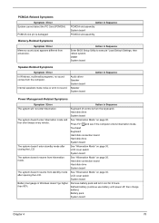
Touchpad Keyboard Hard disk connection board Hard disk drive System board The system doesn't enter standby mode after opening the LCD. Action in Sequence Enter BIOS Setup Utility to execute "Load Default Settings, then reboot system. Action in Sequence PCMCIA slot assembly System board PCMCIA slot assembly Memory-Related Symptoms Symptom / Error Memory count (size) appears different from actual size. LCD cover switch System board The system doesn't resume from hibernation mode. LCD cover switch System board Battery fuel gauge in Sequence The system will not enter ...
Touchpad Keyboard Hard disk connection board Hard disk drive System board The system doesn't enter standby mode after opening the LCD. Action in Sequence Enter BIOS Setup Utility to execute "Load Default Settings, then reboot system. Action in Sequence PCMCIA slot assembly System board PCMCIA slot assembly Memory-Related Symptoms Symptom / Error Memory count (size) appears different from actual size. LCD cover switch System board The system doesn't resume from hibernation mode. LCD cover switch System board Battery fuel gauge in Sequence The system will not enter ...

Acer Aspire 1710 Service Guide
Page 88
Hard disk connection board System board Peripheral-Related Symptoms Symptom / Error System configuration does not match the installed devices. Press Fn+F5, LCD/CRT/Both display switching System board System board Ensure the "Parallel Port" in the "Onboard Devices Configuration" of BIOS Setup Utility is set to Enabled. Touchpad does not work correctly. Action in Sequence Reconnect hard disk/CD-ROM drives. Reconnect hard disk/CD-ROM/diskette drives. Printer driver Printer cable Printer System Board Ensure the "Serial Port" in Sequence Internal modem does not work . Keyboard ...
Hard disk connection board System board Peripheral-Related Symptoms Symptom / Error System configuration does not match the installed devices. Press Fn+F5, LCD/CRT/Both display switching System board System board Ensure the "Parallel Port" in the "Onboard Devices Configuration" of BIOS Setup Utility is set to Enabled. Touchpad does not work correctly. Action in Sequence Reconnect hard disk/CD-ROM drives. Reconnect hard disk/CD-ROM/diskette drives. Printer driver Printer cable Printer System Board Ensure the "Serial Port" in Sequence Internal modem does not work . Keyboard ...
Acer Aspire 1710 Service Guide
Page 89
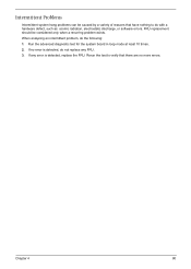
... reasons that there are no error is detected, replace the FRU. Rerun the test to verify that have nothing to do with a hardware defect, such as: cosmic radiation, electrostatic discharge, or software errors. Run the advanced diagnostic test for the system board in loop mode at least 10 times. 2. Intermittent Problems Intermittent system hang problems can be considered only...
... reasons that there are no error is detected, replace the FRU. Rerun the test to verify that have nothing to do with a hardware defect, such as: cosmic radiation, electrostatic discharge, or software errors. Run the advanced diagnostic test for the system board in loop mode at least 10 times. 2. Intermittent Problems Intermittent system hang problems can be considered only...
Acer Aspire 1710 Service Guide
Page 117
... Disassembly CD-ROM/DVD-ROM Module 51 Machine 46 Procedure Flowchart 48 Display 1 display hotkeys 18 Display Standby Mode 30 DVD-ROM Interface 25 E Error Symptom-to-Spare Part Index 73 External CD-ROM Drive Check 69 F Features 1 Flash Utility 44 Floppy Disk Drive Interface 24 FRU (Field Replaceable Unit) List 86 H Hard disk 22, 24 Hard Disk Standby Mode 30 Hardware Specifications and Configurations 22 HDD 22, 24 Hibernation Mode 30 Hibernation mode hotkey 18 Hot Keys 18 I Indicators 14 Intermittent Problems 80 K Keyboard 22, 28 Keyboard or Auxiliary Input Device...
... Disassembly CD-ROM/DVD-ROM Module 51 Machine 46 Procedure Flowchart 48 Display 1 display hotkeys 18 Display Standby Mode 30 DVD-ROM Interface 25 E Error Symptom-to-Spare Part Index 73 External CD-ROM Drive Check 69 F Features 1 Flash Utility 44 Floppy Disk Drive Interface 24 FRU (Field Replaceable Unit) List 86 H Hard disk 22, 24 Hard Disk Standby Mode 30 Hardware Specifications and Configurations 22 HDD 22, 24 Hibernation Mode 30 Hibernation mode hotkey 18 Hot Keys 18 I Indicators 14 Intermittent Problems 80 K Keyboard 22, 28 Keyboard or Auxiliary Input Device...


