Acer Aspire 1660 Service Guide
Page 7
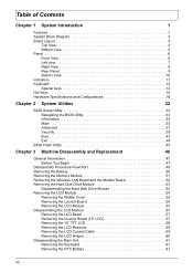
... Exit 44 BIOS Flash Utility 45 Chapter 3 Machine Disassembly and Replacement 46 General Information 47 Before You Begin 47 Disassembly Procedure Flowchart 48 Removing the Battery 50 Removing the Memory Module 51 Removing the Wireless LAN Board and the Modem Board 52 Removing the Hard Disk Drive Module 53 Disassembling the... Brackets 59 Removing the LCD Coaxial Cable 59 Removing the LCD Hinges 60 Disassembling the Main Unit 61 Removing the Keyboard 61 Removing the RTC Battery 61 VII
... Exit 44 BIOS Flash Utility 45 Chapter 3 Machine Disassembly and Replacement 46 General Information 47 Before You Begin 47 Disassembly Procedure Flowchart 48 Removing the Battery 50 Removing the Memory Module 51 Removing the Wireless LAN Board and the Modem Board 52 Removing the Hard Disk Drive Module 53 Disassembling the... Brackets 59 Removing the LCD Coaxial Cable 59 Removing the LCD Hinges 60 Disassembling the Main Unit 61 Removing the Keyboard 61 Removing the RTC Battery 61 VII

Acer Aspire 1660 Service Guide
Page 13
Board Layout Top View 1 Line-in Port 2 Line-out Port 3 RJ45+RJ11 4 LCD Inverter Cable Connector 5 USB Port 6 USB Port 7 USB Port 8 USB Port 9 VGA Port 10 S-Video Port 11 LCD Coaxial Cable Connector 12 Parallel Port 13 DC-in Port 14 LCD Lid Switch 15 CPU Socket 16 North Bridge 17 Fan Connector 18 Second Fan Connector 19 Touchpad Cable Connector 20 HDD Connector 21 Keyboard Connector 22 Speaker Cable Connector 23 Optical Drive Connector 24 South Bridge 25 RTC Battery Connector 26 Launch Board Cable Connector 27 SW5 (Please see Chapter 5 for its settings) 28 PCMCIA Slot 4 Chapter 1
Board Layout Top View 1 Line-in Port 2 Line-out Port 3 RJ45+RJ11 4 LCD Inverter Cable Connector 5 USB Port 6 USB Port 7 USB Port 8 USB Port 9 VGA Port 10 S-Video Port 11 LCD Coaxial Cable Connector 12 Parallel Port 13 DC-in Port 14 LCD Lid Switch 15 CPU Socket 16 North Bridge 17 Fan Connector 18 Second Fan Connector 19 Touchpad Cable Connector 20 HDD Connector 21 Keyboard Connector 22 Speaker Cable Connector 23 Optical Drive Connector 24 South Bridge 25 RTC Battery Connector 26 Launch Board Cable Connector 27 SW5 (Please see Chapter 5 for its settings) 28 PCMCIA Slot 4 Chapter 1

Acer Aspire 1660 Service Guide
Page 19
Unlatches the battery to remove the battery pack. Houses the computer's main memory. 10 Chapter 1 Bottom View # 1 2 3 Item Battery bay Battery release latch Memory compartment Description Houses the computer's battery pack.
Unlatches the battery to remove the battery pack. Houses the computer's main memory. 10 Chapter 1 Bottom View # 1 2 3 Item Battery bay Battery release latch Memory compartment Description Houses the computer's battery pack.
Acer Aspire 1660 Service Guide
Page 20
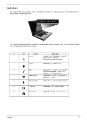
... when it enters into or resumes from hibernation mode. 3 Media Activity Lights when the floppy drive, hard disk or optical drive is active. 4 Battery Charge Lights when the battery is being charged. 5 Caps Lock Lights when Caps Lock is activated. 6 Num Lock Lights when Numeric Lock is closed. # Icon Function Description InviLink...
... when it enters into or resumes from hibernation mode. 3 Media Activity Lights when the floppy drive, hard disk or optical drive is active. 4 Battery Charge Lights when the battery is being charged. 5 Caps Lock Lights when Caps Lock is activated. 6 Num Lock Lights when Numeric Lock is closed. # Icon Function Description InviLink...
Acer Aspire 1660 Service Guide
Page 36
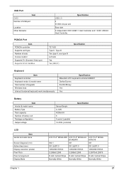
... & external keyboard work simultaneously Specification Mitsubishi LPC keyboard controller M38857 Darfon/Sunrex 84-/85-/88-key Yes Yes Battery Item Vendor & model name Battery Type Pack capacity Number of slots Access location Supports ZV (Zoomed Video) port Supports 32 bit CardBus Specification ....25875 R.G.B. USB Port Item OHCI Number of USB port Location Other Remarks PCMCIA Port Item PCMCIA controller Supports card type Number of battery cell Package configuration Output voltage Sanyo/Simplo Li-ION 4000mAH 8 4 serial 2 parallel 14.4Vdc (nominal) Specification LCD Item Vendor ...
... & external keyboard work simultaneously Specification Mitsubishi LPC keyboard controller M38857 Darfon/Sunrex 84-/85-/88-key Yes Yes Battery Item Vendor & model name Battery Type Pack capacity Number of slots Access location Supports ZV (Zoomed Video) port Supports 32 bit CardBus Specification ....25875 R.G.B. USB Port Item OHCI Number of USB port Location Other Remarks PCMCIA Port Item PCMCIA controller Supports card type Number of battery cell Package configuration Output voltage Sanyo/Simplo Li-ION 4000mAH 8 4 serial 2 parallel 14.4Vdc (nominal) Specification LCD Item Vendor ...
Acer Aspire 1660 Service Guide
Page 39
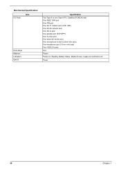
Mechanical Specification I/O Ports Item Drive Bays Material Indicators Switch Specification Two Type II or one Type III PC CardBus (PCMCIA) slot One IEEE 1394 port One FIR port One RJ-11 modem jack (V.92, 56K) One RJ-45 network jack One DC-in jack One parallel port (ECP/EPP) One S-video port One external monitor port One microphone-in jack (3.5mm mini jack) One headphone jack (3.5mm mini jack) Four USB 2.0 ports One Plastic Power-on, Standby, Battery Status, Media Access, CapsLock and NumLock Power 30 Chapter 1
Mechanical Specification I/O Ports Item Drive Bays Material Indicators Switch Specification Two Type II or one Type III PC CardBus (PCMCIA) slot One IEEE 1394 port One FIR port One RJ-11 modem jack (V.92, 56K) One RJ-45 network jack One DC-in jack One parallel port (ECP/EPP) One S-video port One external monitor port One microphone-in jack (3.5mm mini jack) One headphone jack (3.5mm mini jack) Four USB 2.0 ports One Plastic Power-on, Standby, Battery Status, Media Access, CapsLock and NumLock Power 30 Chapter 1

Acer Aspire 1660 Service Guide
Page 45
... format. (hour:minute:second) System Time Sets the system date. Parameter System Time System Date System Memory Extended Memory VGA Memory Fast Boot Power on battery power). Extended Memory size=Total memory size-1MB Shows the VGA memory size. This is because the user is NOT available (running on display LCD...
... format. (hour:minute:second) System Time Sets the system date. Parameter System Time System Date System Memory Extended Memory VGA Memory Fast Boot Power on battery power). Extended Memory size=Total memory size-1MB Shows the VGA memory size. This is because the user is NOT available (running on display LCD...
Acer Aspire 1660 Service Guide
Page 54
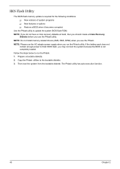
... the BIOS is required for the following conditions: T New versions of system programs T New features or options T Restore a BIOS when it becomes corrupted. If the battery pack does not contain enough power to run the Phlash utility. Fellow the steps below to finish BIOS flash, you use the Phlash. Then boot...
... the BIOS is required for the following conditions: T New versions of system programs T New features or options T Restore a BIOS when it becomes corrupted. If the battery pack does not contain enough power to run the Phlash utility. Fellow the steps below to finish BIOS flash, you use the Phlash. Then boot...

Acer Aspire 1660 Service Guide
Page 57
... disassemble the inside assembly frame in that need to remove the main board, you on the components that order. Start Battery HDD Module G*2 HDD HDD Holder *2 DIMM Cover Memory *2 Modem Cover Hinge Caps Wireless LAN Board D*2 Modem Board J*2 Middle Cover RTC... Battery Keyboard F*6 LCD Module *2 Launch Board Second Fan J*3 Bracket Lower Case Assembly J*2 FDD Module J*5 F*10 D*4 Upper Case Assembly D*4 Wireless LAN Antenna Touchpad Cover...
... disassemble the inside assembly frame in that need to remove the main board, you on the components that order. Start Battery HDD Module G*2 HDD HDD Holder *2 DIMM Cover Memory *2 Modem Cover Hinge Caps Wireless LAN Board D*2 Modem Board J*2 Middle Cover RTC... Battery Keyboard F*6 LCD Module *2 Launch Board Second Fan J*3 Bracket Lower Case Assembly J*2 FDD Module J*5 F*10 D*4 Upper Case Assembly D*4 Wireless LAN Antenna Touchpad Cover...

Acer Aspire 1660 Service Guide
Page 59
Then slide the battery out from the machine. To remove the battery, push the battery release latch. 2. Chapter 3 50 Removing the Battery 1.
Then slide the battery out from the machine. To remove the battery, push the battery release latch. 2. Chapter 3 50 Removing the Battery 1.

Acer Aspire 1660 Service Guide
Page 60
See "Removing the Battery" on page 50. 2. To remove the memory module from the machine, first remove the two screws holding the dimm cover. 3. Remove the dimm cover. 4. Then remove the memory. 51 Chapter 3 Pop up the memory. 5. Removing the Memory Module 1.
See "Removing the Battery" on page 50. 2. To remove the memory module from the machine, first remove the two screws holding the dimm cover. 3. Remove the dimm cover. 4. Then remove the memory. 51 Chapter 3 Pop up the memory. 5. Removing the Memory Module 1.

Acer Aspire 1660 Service Guide
Page 61
Disconnect the wireless antennae. 5. Chapter 3 52 Detach the modem board and disconnect the modem cable carefully, then remove the modem board. Removing the Wireless LAN Board and the Modem Board 1. To remove the wireless LAN board, first remove the two screws holding the modem cover. 3. To remove the modem board, first remove the two screws fastening the modem board. 7. Remove the modem cover from the machine. 4. Pop out the wireless LAN board. 6. See "Removing the Battery" on page 50. 2.
Disconnect the wireless antennae. 5. Chapter 3 52 Detach the modem board and disconnect the modem cable carefully, then remove the modem board. Removing the Wireless LAN Board and the Modem Board 1. To remove the wireless LAN board, first remove the two screws holding the modem cover. 3. To remove the modem board, first remove the two screws fastening the modem board. 7. Remove the modem cover from the machine. 4. Pop out the wireless LAN board. 6. See "Removing the Battery" on page 50. 2.
Acer Aspire 1660 Service Guide
Page 62
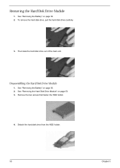
See "Removing the Battery" on page 50. 2. See "Removing the Battery" on page 50. 2. Detach the hard disk drive from the HDD holder. 53 Chapter 3 Disassembling the Hard Disk Drive Module 1. Remove the two screws that fasten the HDD holder. 4. See "Removing the Hard Disk Drive Module" on page 53. 3. Then take the hard disk drive out of the main unit. Removing the Hard Disk Drive Module 1. To remove the hard disk drive, pull the hard disk dirve carefully. 3.
See "Removing the Battery" on page 50. 2. See "Removing the Battery" on page 50. 2. Detach the hard disk drive from the HDD holder. 53 Chapter 3 Disassembling the Hard Disk Drive Module 1. Remove the two screws that fasten the HDD holder. 4. See "Removing the Hard Disk Drive Module" on page 53. 3. Then take the hard disk drive out of the main unit. Removing the Hard Disk Drive Module 1. To remove the hard disk drive, pull the hard disk dirve carefully. 3.

Acer Aspire 1660 Service Guide
Page 63
See "Removing the Battery" on the other side. 6. Detach the middle cover from the machine. 7. Remove the left hinge cap. 5. Removing the Launch Board 1. Then remove the screw holding the middle cover on page 50. Removing the LCD Module Removing the Middle Cover 1. Remove the screw that secures the middle cover. 4. See "Removing the Battery" on page 50. 2. Disconnect the launch board cable then remove the middle cover off the main unit. . To remove the middle cover, first use a plastic flat screwdriver to remove the right hinge cap. 3. Chapter 3 54
See "Removing the Battery" on the other side. 6. Detach the middle cover from the machine. 7. Remove the left hinge cap. 5. Removing the Launch Board 1. Then remove the screw holding the middle cover on page 50. Removing the LCD Module Removing the Middle Cover 1. Remove the screw that secures the middle cover. 4. See "Removing the Battery" on page 50. 2. Disconnect the launch board cable then remove the middle cover off the main unit. . To remove the middle cover, first use a plastic flat screwdriver to remove the right hinge cap. 3. Chapter 3 54

Acer Aspire 1660 Service Guide
Page 64
See "Removing the Battery" on the bottom; Remove the two screws on page 50. 2. 2. Remove the screw that fastens the LCD coaxial cable and disconnect the cable. one on ...
See "Removing the Battery" on the bottom; Remove the two screws on page 50. 2. 2. Remove the screw that fastens the LCD coaxial cable and disconnect the cable. one on ...

Acer Aspire 1660 Service Guide
Page 66
... bezel carefully, and then remove the LCD bezel from the inverter board. 7. See "Removing the Middle Cover" on page 55. 5. See "Removing the Battery" on page 54. 4. To remove the inverter board, first remove one screw from the LCD module. See "Removing the Launch Board" on page 50.... 2. Disassembling the LCD Module Removing the LCD Bezel 1. See "Removing the Battery" on page 54. 3. Removing the Inverter Board (15" LCD) 1. See "Removing the Middle Cover" on page 50. 2. See "Removing the Launch Board...
... bezel carefully, and then remove the LCD bezel from the inverter board. 7. See "Removing the Middle Cover" on page 55. 5. See "Removing the Battery" on page 54. 4. To remove the inverter board, first remove one screw from the LCD module. See "Removing the Launch Board" on page 50.... 2. Disassembling the LCD Module Removing the LCD Bezel 1. See "Removing the Battery" on page 54. 3. Removing the Inverter Board (15" LCD) 1. See "Removing the Middle Cover" on page 50. 2. See "Removing the Launch Board...

Acer Aspire 1660 Service Guide
Page 67
... the LCD Module" on page 54. 3. See "Removing the LCD Bezel" on page 54. 4. See "Removing the Launch Board" on page 57. 6. See "Removing the Battery" on page 57. 7. Then take the LCD out of the LCD panel. See "Removing the Inverter Board (15" LCD)" on page 50. 2. Chapter 3 58
... the LCD Module" on page 54. 3. See "Removing the LCD Bezel" on page 54. 4. See "Removing the Launch Board" on page 57. 6. See "Removing the Battery" on page 57. 7. Then take the LCD out of the LCD panel. See "Removing the Inverter Board (15" LCD)" on page 50. 2. Chapter 3 58

Acer Aspire 1660 Service Guide
Page 68
..." on page 54. 3. Tear off the mylar fastening the LCD coaxial cable, then disconnect the coaxial cable. 59 Chapter 3 See "Removing the Battery" on page 50. 2. See "Removing the Battery" on page 50. 2. See "Removing the LCD Bezel" on page 57. 6. Removing the LCD Brackets 1. See "Removing the LCD Bezel" on page...
..." on page 54. 3. Tear off the mylar fastening the LCD coaxial cable, then disconnect the coaxial cable. 59 Chapter 3 See "Removing the Battery" on page 50. 2. See "Removing the Battery" on page 50. 2. See "Removing the LCD Bezel" on page 57. 6. Removing the LCD Brackets 1. See "Removing the LCD Bezel" on page...

Acer Aspire 1660 Service Guide
Page 69
See "Removing the Launch Board" on page 55. 5. See "Removing the LCD Module" on page 54. 4. Remove the screw holding the left hinge, then remove the left hinge. Remove the screw holding the right hinge, then remove the right hinge. 9. See "Removing the Inverter Board (15" LCD)" on page 54. 3. See "Removing the Middle Cover" on page 57. 7. See "Removing the Battery" on page 58. 8. See "Removing the 15" TFT LCD" on page 50. 2. Chapter 3 60 Removing the LCD Hinges 1. See "Removing the LCD Bezel" on page 57. 6.
See "Removing the Launch Board" on page 55. 5. See "Removing the LCD Module" on page 54. 4. Remove the screw holding the left hinge, then remove the left hinge. Remove the screw holding the right hinge, then remove the right hinge. 9. See "Removing the Inverter Board (15" LCD)" on page 54. 3. See "Removing the Middle Cover" on page 57. 7. See "Removing the Battery" on page 58. 8. See "Removing the 15" TFT LCD" on page 50. 2. Chapter 3 60 Removing the LCD Hinges 1. See "Removing the LCD Bezel" on page 57. 6.

Acer Aspire 1660 Service Guide
Page 70
... fan. 61 Chapter 3 To remove the keyboard, carefully pull the keyboard out and upwards as the pticute shows. 4. See "Removing the Battery" on page 61. 4. Removing the Fan 1. Disconnect the RTC battery cable then remove it. See "Removing the Middle Cover" on page 54. 3. See "Removing the Middle Cover" on page 54.... 3. See "Removing the Middle Cover" on page 50. 2. Disconnect the fan cable and remove the three screws fastening the fan. See "Removing the Battery" on page 54. 3. See "Removing the Keyboard" on page 50. 2. See "Removing the...
... fan. 61 Chapter 3 To remove the keyboard, carefully pull the keyboard out and upwards as the pticute shows. 4. See "Removing the Battery" on page 61. 4. Removing the Fan 1. Disconnect the RTC battery cable then remove it. See "Removing the Middle Cover" on page 54. 3. See "Removing the Middle Cover" on page 54.... 3. See "Removing the Middle Cover" on page 50. 2. Disconnect the fan cable and remove the three screws fastening the fan. See "Removing the Battery" on page 54. 3. See "Removing the Keyboard" on page 50. 2. See "Removing the...


