
Altos R700 Chassis Subassembly
Page 4
... FCC regulations. Operation is subject to the following two conditions: (1) this device may not cause harmful interference, and (2) this device must be attached to this server. Changes or modifications not expressly approved by the manufacturer could void the user's authority, which is likely to result in interference to maintain compliance with...
... FCC regulations. Operation is subject to the following two conditions: (1) this device may not cause harmful interference, and (2) this device must be attached to this server. Changes or modifications not expressly approved by the manufacturer could void the user's authority, which is likely to result in interference to maintain compliance with...

Altos R700 Chassis Subassembly
Page 7
... System Components 21 Remove the Cover 21 Remove the Processor Air Duct 22 Remove the Riser Cards 22 Remove the Fan module 23 Install the Server Board 24 Routing Cables 27 Installing Peripherals 35 Installing a PCI Card on a Riser Card 35 Installing the Riser Cards on the... Server Board 36 Installing a Hard Drive 37 Installing a DVD drive/FDD or CD-ROM drive/FDD Module 39 Finishing Installation 41 Installing a Serial A port in the ...
... System Components 21 Remove the Cover 21 Remove the Processor Air Duct 22 Remove the Riser Cards 22 Remove the Fan module 23 Install the Server Board 24 Routing Cables 27 Installing Peripherals 35 Installing a PCI Card on a Riser Card 35 Installing the Riser Cards on the... Server Board 36 Installing a Hard Drive 37 Installing a DVD drive/FDD or CD-ROM drive/FDD Module 39 Finishing Installation 41 Installing a Serial A port in the ...

Altos R700 Chassis Subassembly
Page 8
3 Installing the System in a Rack 43 Equipment Rack Precautions 44 4 Working Inside Your Server 47 Tools and Supplies Needed 48 Safety: Before You Remove the Cover 48 Warnings and Cautions 49 Lithium Battery Replacement 49 Replacing ...Power Supply Cage 57 Installing a Redundant Fan 59 Replacing the Fan Module 61 Replacing a Backplane Board 62 Replacing a Front Panel Board 63 Replacing a Server Board 64 Appendix A: Equipment Log and Worksheets 67 Equipment Log 68 Current Usage 70 Calculating Power Usage 70 Worksheet, Calculating DC Power Usage 70 Worksheet...
3 Installing the System in a Rack 43 Equipment Rack Precautions 44 4 Working Inside Your Server 47 Tools and Supplies Needed 48 Safety: Before You Remove the Cover 48 Warnings and Cautions 49 Lithium Battery Replacement 49 Replacing ...Power Supply Cage 57 Installing a Redundant Fan 59 Replacing the Fan Module 61 Replacing a Backplane Board 62 Replacing a Front Panel Board 63 Replacing a Server Board 64 Appendix A: Equipment Log and Worksheets 67 Equipment Log 68 Current Usage 70 Calculating Power Usage 70 Worksheet, Calculating DC Power Usage 70 Worksheet...
Altos R700 Chassis Subassembly
Page 10
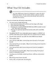
... to backplane board) • One internal front panel cable, 34-pin (connecting front panel board to support the Altos R700 Server Board. Your kit includes the following components: • 2U rack-mount chassis featuring: • Four hard drive bays with carriers and ...one blank • Two PCI riser cards for shipment, but you must remove and reinstall them when you install the server board. 2 What Your Kit Includes 1 Chassis Description Your Altos R700 server chassis kit is designed to backplane board) • One Resource CD-ROM containing drivers, utilities, and product guide •...
... to backplane board) • One internal front panel cable, 34-pin (connecting front panel board to support the Altos R700 Server Board. Your kit includes the following components: • 2U rack-mount chassis featuring: • Four hard drive bays with carriers and ...one blank • Two PCI riser cards for shipment, but you must remove and reinstall them when you install the server board. 2 What Your Kit Includes 1 Chassis Description Your Altos R700 server chassis kit is designed to backplane board) • One Resource CD-ROM containing drivers, utilities, and product guide •...

Altos R700 Chassis Subassembly
Page 11
3 Items You Must Purchase Separately The following components must be purchased separately: • Front bezel (optional) • Altos R700 Server Board • Minimum of one Intel® Xeon™ processor • Registered ECC DDR RAM memory DIMMs • SCSI hard disk drives (HDD) • Slimline ...
3 Items You Must Purchase Separately The following components must be purchased separately: • Front bezel (optional) • Altos R700 Server Board • Minimum of one Intel® Xeon™ processor • Registered ECC DDR RAM memory DIMMs • SCSI hard disk drives (HDD) • Slimline ...

Altos R700 Chassis Subassembly
Page 17
...button Reset button NMI button ID button Toggles the system power on from behind a rack of the chassis and allows you to locate the server you're working on /off the front panel ID LED and the baseboard ID LED. Continuous amber light (Note 1) indicates the system ...state for ACPI compliant operating systems. Reboots and initializes the system. Blinking amber light (Note 1) indicates the system is visible through the rear of servers. The baseboard ID LED is in a degraded condition. LED Indicator Status Power/sleep LED NIC 1 activity LED NIC 2 activity LED System status ...
...button Reset button NMI button ID button Toggles the system power on from behind a rack of the chassis and allows you to locate the server you're working on /off the front panel ID LED and the baseboard ID LED. Continuous amber light (Note 1) indicates the system ...state for ACPI compliant operating systems. Reboots and initializes the system. Blinking amber light (Note 1) indicates the system is visible through the rear of servers. The baseboard ID LED is in a degraded condition. LED Indicator Status Power/sleep LED NIC 1 activity LED NIC 2 activity LED System status ...

Altos R700 Chassis Subassembly
Page 21
Chassis Security To help prevent unauthorized access to the Baseboard Management Controller (BMC) on the server board, where server management software processes the signal. When the cover is opened, the switch, located on the front panel board, transmits a signal to the system's ...locked and cannot be opened . The chassis also includes a preinstalled intrusion switch for cooling. The bezel is now unlocked and can be monitored by server management software. 13 pull cooling air through the chassis. Locking and Unlocking the Front Bezel To unlock the bezel, insert the key in the ...
Chassis Security To help prevent unauthorized access to the Baseboard Management Controller (BMC) on the server board, where server management software processes the signal. When the cover is opened, the switch, located on the front panel board, transmits a signal to the system's ...locked and cannot be opened . The chassis also includes a preinstalled intrusion switch for cooling. The bezel is now unlocked and can be monitored by server management software. 13 pull cooling air through the chassis. Locking and Unlocking the Front Bezel To unlock the bezel, insert the key in the ...

Altos R700 Chassis Subassembly
Page 25
17 Before You Begin Supplies Needed Before beginning your work, make sure you have the following supplies available: • Anti-static wrist strap (recommended) • Altos R700 accessory kit (included) • Altos R700 Server Board • Processors and memory you purchased separately to add to the server board • Optional peripherals and add-in cards you want to include in the system
17 Before You Begin Supplies Needed Before beginning your work, make sure you have the following supplies available: • Anti-static wrist strap (recommended) • Altos R700 accessory kit (included) • Altos R700 Server Board • Processors and memory you purchased separately to add to the server board • Optional peripherals and add-in cards you want to include in the system

Altos R700 Chassis Subassembly
Page 27
It must have a current rating that is at least 125% of the current rating of the server. • The plug on the power cord that plugs into the wall outlet must be a grounding-type male plug designed for use the supplied ... safety guidelines: 1. Only a technically qualified person should integrate and configure the server. Then unplug all peripheral devices connected to the server. 2. 19 Checking the Power Cord Warning: Do not attempt to access components inside the server. Turn off the server by an agency acceptable in your region. The socket outlets must be installed...
It must have a current rating that is at least 125% of the current rating of the server. • The plug on the power cord that plugs into the wall outlet must be a grounding-type male plug designed for use the supplied ... safety guidelines: 1. Only a technically qualified person should integrate and configure the server. Then unplug all peripheral devices connected to the server. 2. 19 Checking the Power Cord Warning: Do not attempt to access components inside the server. Turn off the server by an agency acceptable in your region. The socket outlets must be installed...

Altos R700 Chassis Subassembly
Page 28
Warning: The power button on the front panel DOES NOT turn off the server and disconnect the power cords, telecommunications systems, networks, and modems attached to I/O connectors or ports on power, telephone, and communication cables. Turn off ...power from the wall outlet or the chassis. Label and disconnect all peripheral cables and all AC power cords from the server, you must unplug all telecommunication lines connected to the server before opening it. Otherwise, personal injury or equipment damage can result. Refer servicing of the chassis. 4. Provide some electrostatic...
Warning: The power button on the front panel DOES NOT turn off the server and disconnect the power cords, telecommunications systems, networks, and modems attached to I/O connectors or ports on power, telephone, and communication cables. Turn off ...power from the wall outlet or the chassis. Label and disconnect all peripheral cables and all AC power cords from the server, you must unplug all telecommunication lines connected to the server before opening it. Otherwise, personal injury or equipment damage can result. Refer servicing of the chassis. 4. Provide some electrostatic...

Altos R700 Chassis Subassembly
Page 32
...the corresponding shouldered standoffs. System components must be installed in the order presented below the studs in the rear chassis wall. 2 Remove the server board from its packaging and antistatic bag. 3 While placing the board on the chassis standoffs, carefully position the board I/O connectors in ...the rear chassis I/O openings. 4 Adjust board position so that the edge of the chassis. 2 Assembling the System Install the Server Board Caution: Do not install any server board support bumpers in the Altos R700 chassis. 24 6 Lift the fan module out of the sheet is seated below .
...the corresponding shouldered standoffs. System components must be installed in the order presented below the studs in the rear chassis wall. 2 Remove the server board from its packaging and antistatic bag. 3 While placing the board on the chassis standoffs, carefully position the board I/O connectors in ...the rear chassis I/O openings. 4 Adjust board position so that the edge of the chassis. 2 Assembling the System Install the Server Board Caution: Do not install any server board support bumpers in the Altos R700 chassis. 24 6 Lift the fan module out of the sheet is seated below .

Altos R700 Chassis Subassembly
Page 33
25 5 Attach the board to the chassis using the three screws shipped in the chassis accessory kit. 6 Install processors and memory, following the directions on the Altos R700 Server Board Product Guide. 7 If you only install one processor, you must install the processor air dam.
25 5 Attach the board to the chassis using the three screws shipped in the chassis accessory kit. 6 Install processors and memory, following the directions on the Altos R700 Server Board Product Guide. 7 If you only install one processor, you must install the processor air dam.

Altos R700 Chassis Subassembly
Page 34
26 2 Assembling the System a Attach processor retention piece (B) to the server board (C) using the provided screws (A). b Put the air dam(D) into place.
26 2 Assembling the System a Attach processor retention piece (B) to the server board (C) using the provided screws (A). b Put the air dam(D) into place.

Altos R700 Chassis Subassembly
Page 36
... SCSI Backplane (shown horizontal for clarity) Server Board To backplane power connector from power supply To server board primary power connector from power supply Floppy/FP/IDE flex circuit cable from server board to backplane SCSI cable from server board to backplane USB ribbon cable from ... Ribbon cable from front panel board to backplane Fan module to server board fan connectors (2) To server board auxiliary signal connector from power supply To server board auxiliary power connector from power supply Serial cable from server board to knockout on back of chassis Connect Power Cables 1...
... SCSI Backplane (shown horizontal for clarity) Server Board To backplane power connector from power supply To server board primary power connector from power supply Floppy/FP/IDE flex circuit cable from server board to backplane SCSI cable from server board to backplane USB ribbon cable from ... Ribbon cable from front panel board to backplane Fan module to server board fan connectors (2) To server board auxiliary signal connector from power supply To server board auxiliary power connector from power supply Serial cable from server board to knockout on back of chassis Connect Power Cables 1...

Altos R700 Chassis Subassembly
Page 37
Install the Fan module Caution: When installing the fan module, avoid pinching cables routed in the area. 1 Note the raised tabs on the chassis floor and the corresponding holes in the bottom of the fan module. 2 Lower the fan module until they are fully seated. Firmly press the two connectors together until it is just above the chassis floor. 3 Align the holes in the fan module with the raised tabs on the server board. 29 2 Connect the main server board power cable to the white 24-pin connector on the chassis and lower the fan module onto the floor.
Install the Fan module Caution: When installing the fan module, avoid pinching cables routed in the area. 1 Note the raised tabs on the chassis floor and the corresponding holes in the bottom of the fan module. 2 Lower the fan module until they are fully seated. Firmly press the two connectors together until it is just above the chassis floor. 3 Align the holes in the fan module with the raised tabs on the server board. 29 2 Connect the main server board power cable to the white 24-pin connector on the chassis and lower the fan module onto the floor.

Altos R700 Chassis Subassembly
Page 38
30 2 Assembling the System 4 While pressing down on the server board. Connect the end marked "P1-Motherboard" to the floppy/ front panel/IDE connector on the fan module, slide it in the accessory kit. Route the cable to the server board. Connect Flex Circuit Cable 1 Remove the flex circuit cable from the cable bag in the direction of arrow (2) until the latch snaps into place. 5 Connect the fan power cables to
30 2 Assembling the System 4 While pressing down on the server board. Connect the end marked "P1-Motherboard" to the floppy/ front panel/IDE connector on the fan module, slide it in the accessory kit. Route the cable to the server board. Connect Flex Circuit Cable 1 Remove the flex circuit cable from the cable bag in the direction of arrow (2) until the latch snaps into place. 5 Connect the fan power cables to

Altos R700 Chassis Subassembly
Page 40
Connect Auxiliary Power Cables 1 Connect the auxiliary power cable to the 8-pin auxiliary power connector on the server board (A). 2 Connect the signal cable to the 5-pin signal connector on the server board (B). 32 2 Assembling the System 2 Install the flex circuit cable retention clip. It snaps into place over the backplane and flex circuit cable.
Connect Auxiliary Power Cables 1 Connect the auxiliary power cable to the 8-pin auxiliary power connector on the server board (A). 2 Connect the signal cable to the 5-pin signal connector on the server board (B). 32 2 Assembling the System 2 Install the flex circuit cable retention clip. It snaps into place over the backplane and flex circuit cable.

Altos R700 Chassis Subassembly
Page 41
Make sure the cable does not lay on top of the corner of the fan module and connect it will get damaged when you install the top cover. 2 Install the processor duct. Route the cable along the top of the backplane or it to the USB connector on the front panel. 33 Finish Cable Routing 1 Connect the USB cable to the server board.
Make sure the cable does not lay on top of the corner of the fan module and connect it will get damaged when you install the top cover. 2 Install the processor duct. Route the cable along the top of the backplane or it to the USB connector on the front panel. 33 Finish Cable Routing 1 Connect the USB cable to the server board.

Altos R700 Chassis Subassembly
Page 42
... the front panel cable is connected to the front panel board, routed over USB cable to the backplane, and connected to the connector on the server board. 34 2 Assembling the System 3 If it isn't installed, install the power supply air baffle.
... the front panel cable is connected to the front panel board, routed over USB cable to the backplane, and connected to the connector on the server board. 34 2 Assembling the System 3 If it isn't installed, install the power supply air baffle.

Altos R700 Chassis Subassembly
Page 43
...and a tape drive. Installing a PCI Card on a Riser Card The riser card nearest the chassis sidewall (see "Installing the Riser Cards on the Server Board" on a riser card while the riser card is removed from the rear retention bracket (B) of the riser card. 35 Installing Peripherals Peripherals and ...in cards. The riser card on the chassis centerline (see "Installing the Riser Cards on the Server Board" on page 36. The following sections describe how to "Installing the Riser Cards on the Server Board" on page 36, B) supports three Low Profile (LP) PCI add-in your full-length...
...and a tape drive. Installing a PCI Card on a Riser Card The riser card nearest the chassis sidewall (see "Installing the Riser Cards on the Server Board" on a riser card while the riser card is removed from the rear retention bracket (B) of the riser card. 35 Installing Peripherals Peripherals and ...in cards. The riser card on the chassis centerline (see "Installing the Riser Cards on the Server Board" on page 36. The following sections describe how to "Installing the Riser Cards on the Server Board" on page 36, B) supports three Low Profile (LP) PCI add-in your full-length...


