
Altos R700 Chassis Subassembly
Page 7
... 17 Supplies Needed 17 Installation/Assembly Safety Instructions 18 Use Only for Intended Applications 18 Checking the Power Cord 19 Warnings and Cautions 19 Installing System Components 21 Remove the Cover 21 Remove the Processor Air Duct 22 Remove the Riser Cards 22 Remove the Fan module 23 Install the Server Board 24 Routing Cables 27 Installing Peripherals 35 Installing a PCI Card on a Riser Card 35 Installing the Riser Cards on the Server Board 36 Installing a Hard Drive 37 Installing a DVD drive/FDD or CD-ROM drive/FDD Module...
... 17 Supplies Needed 17 Installation/Assembly Safety Instructions 18 Use Only for Intended Applications 18 Checking the Power Cord 19 Warnings and Cautions 19 Installing System Components 21 Remove the Cover 21 Remove the Processor Air Duct 22 Remove the Riser Cards 22 Remove the Fan module 23 Install the Server Board 24 Routing Cables 27 Installing Peripherals 35 Installing a PCI Card on a Riser Card 35 Installing the Riser Cards on the Server Board 36 Installing a Hard Drive 37 Installing a DVD drive/FDD or CD-ROM drive/FDD Module...

Altos R700 Chassis Subassembly
Page 8
...Equipment Rack Precautions 44 4 Working Inside Your Server 47 Tools and Supplies Needed 48 Safety: Before You Remove the Cover 48 Warnings and Cautions 49 Lithium Battery Replacement 49 Replacing Components 51 Replacing a Hard Drive 51 Replacing a DVD/CD-ROM drive/FDD Module 52 Replacing a PCI Add-in Card 54 Replacing a 500 Watt Power Supply Module 56 Replacing a Power Supply Cage 57 Installing a Redundant Fan 59 Replacing the Fan Module 61 Replacing a Backplane Board 62 Replacing a Front Panel Board 63 Replacing a Server Board 64 Appendix A: Equipment Log and...
...Equipment Rack Precautions 44 4 Working Inside Your Server 47 Tools and Supplies Needed 48 Safety: Before You Remove the Cover 48 Warnings and Cautions 49 Lithium Battery Replacement 49 Replacing Components 51 Replacing a Hard Drive 51 Replacing a DVD/CD-ROM drive/FDD Module 52 Replacing a PCI Add-in Card 54 Replacing a 500 Watt Power Supply Module 56 Replacing a Power Supply Cage 57 Installing a Redundant Fan 59 Replacing the Fan Module 61 Replacing a Backplane Board 62 Replacing a Front Panel Board 63 Replacing a Server Board 64 Appendix A: Equipment Log and...
Altos R700 Chassis Subassembly
Page 10
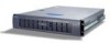
... filler panel) • One 480 W SSI PFC non-redundant power supply or a 500 W 1+0 SSI PFC redundant power supply with one module and one blank • Two PCI riser cards for shipment, but you must remove and reinstall them when you install the server board. 2 What Your Kit Includes 1 Chassis Description Your Altos R700 server chassis kit is designed to backplane board) • One Resource CD-ROM containing drivers, utilities, and product guide • Mounting screws (server board) •...
... filler panel) • One 480 W SSI PFC non-redundant power supply or a 500 W 1+0 SSI PFC redundant power supply with one module and one blank • Two PCI riser cards for shipment, but you must remove and reinstall them when you install the server board. 2 What Your Kit Includes 1 Chassis Description Your Altos R700 server chassis kit is designed to backplane board) • One Resource CD-ROM containing drivers, utilities, and product guide • Mounting screws (server board) •...
Altos R700 Chassis Subassembly
Page 18
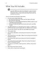
... off due to the Baseboard Management Controller (BMC), or the system board must send a Set Fault Indication command to a failure or configuration change that prevents the BIOS from running. Also off when the system is powered off or in effect at the time of power off will be blinking at the same time that the Power LED will be used with the 2U Altos R700 hot swappable backplane. 3. If the system is...
... off due to the Baseboard Management Controller (BMC), or the system board must send a Set Fault Indication command to a failure or configuration change that prevents the BIOS from running. Also off when the system is powered off or in effect at the time of power off will be blinking at the same time that the Power LED will be used with the 2U Altos R700 hot swappable backplane. 3. If the system is...

Altos R700 Chassis Subassembly
Page 20
... turned off. The system fans are hot swappable. When a drive fails, the SCSI backplane detects the failure, reports it, and powers down the failed drive. It is applied to For information on installation, see "Installing a DVD drive/FDD or CDROM drive/FDD Module" on page 39. 500 Watt Redundant Power Supply The power supply consists of the chassis to the drive and the drive fault LED becomes a random blinking green light. The drive fault LED becomes a continuous amber light. After the failed drive is removed and a new drive...
... turned off. The system fans are hot swappable. When a drive fails, the SCSI backplane detects the failure, reports it, and powers down the failed drive. It is applied to For information on installation, see "Installing a DVD drive/FDD or CDROM drive/FDD Module" on page 39. 500 Watt Redundant Power Supply The power supply consists of the chassis to the drive and the drive fault LED becomes a random blinking green light. The drive fault LED becomes a continuous amber light. After the failed drive is removed and a new drive...

Altos R700 Chassis Subassembly
Page 42
... to route the SCSI cable after the full length PCI riser card is installed. 5 Ensure that the front panel cable is connected to the front panel board, routed over USB cable to the backplane, and connected to the SCSI connector on the server board. All cables from the power supply should route through the notch in the bottom of the power supply air baffle, to the connector on the side of the processor duct, through...
... to route the SCSI cable after the full length PCI riser card is installed. 5 Ensure that the front panel cable is connected to the front panel board, routed over USB cable to the backplane, and connected to the SCSI connector on the server board. All cables from the power supply should route through the notch in the bottom of the power supply air baffle, to the connector on the side of the processor duct, through...

Altos R700 Chassis Subassembly
Page 43
... cards, hard disk drives, a DVD/CD-ROM drive/floppy disk drive, and a tape drive. Note: If your system and must be purchased separately. PCI add-in cards must be installed on page 36, A) supports three full-length, full-height PCI add-in cards or three LP cards (an LP card must be equipped with a standard full-height PCI mounting bracket). Installing a PCI Card on a Riser Card The riser card nearest the chassis sidewall (see "Installing the Riser Cards on the Server Board...
... cards, hard disk drives, a DVD/CD-ROM drive/floppy disk drive, and a tape drive. Note: If your system and must be purchased separately. PCI add-in cards must be installed on page 36, A) supports three full-length, full-height PCI add-in cards or three LP cards (an LP card must be equipped with a standard full-height PCI mounting bracket). Installing a PCI Card on a Riser Card The riser card nearest the chassis sidewall (see "Installing the Riser Cards on the Server Board...
Altos R700 Chassis Subassembly
Page 52
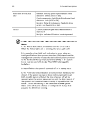
... Altos R700 chassis comes equipped with a rack mount kit that are part of the rack, then you must provide proper grounding for the rack itself. MAIN AC POWER DISCONNECT: You are plugged into AC outlets that can cause a variety of over when one server is installed in the rack, the power source for the equipment rack is designed for an AC line voltage source with the rack installation...
... Altos R700 chassis comes equipped with a rack mount kit that are part of the rack, then you must provide proper grounding for the rack itself. MAIN AC POWER DISCONNECT: You are plugged into AC outlets that can cause a variety of over when one server is installed in the rack, the power source for the equipment rack is designed for an AC line voltage source with the rack installation...
Altos R700 Chassis Subassembly
Page 71
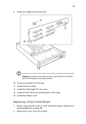
Replacing a Front Panel Board 1 Before removing the cover to the board. 11 Install the fan module. 12 Install the full-height PCI riser card. 13 Install all hard drives and peripherals in their bays. 14 Install the chassis cover. 63 9 Install and tighten the thumscrew. Caution: Carefully route cables in their original paths to minimize airflow blockage and cooling problems. 10 Connect all cables to work inside the system, observe the safety guidelines on page 48. 2 Remove the cover from the chassis.
Replacing a Front Panel Board 1 Before removing the cover to the board. 11 Install the fan module. 12 Install the full-height PCI riser card. 13 Install all hard drives and peripherals in their bays. 14 Install the chassis cover. 63 9 Install and tighten the thumscrew. Caution: Carefully route cables in their original paths to minimize airflow blockage and cooling problems. 10 Connect all cables to work inside the system, observe the safety guidelines on page 48. 2 Remove the cover from the chassis.

Altos R700 Service Guide
Page 6
... Menu 30 Advanced Chipset Control 31 PCI Configuration 32 PCI Device, Embedded Devices 33 I/O Device / Peripheral Configuration 36 Memory Configuration 40 Security 41 Server 43 System Management 45 Serial Console Redirection 46 Event Log Configuration 50 Boot 51 Boot Device Priority 52 Hard Drive 54 Removable Devices 55 Exit 56 Fault Resilient Booting 59 Chapter 3 Machine Disassembly and Replacement 60 Disassembly FlowChart 61 General Information 62 Before You Begin 62 Opening the Housing Panels 63 Removing the cover 63 Removing the Riser Card 64 Removing...
... Menu 30 Advanced Chipset Control 31 PCI Configuration 32 PCI Device, Embedded Devices 33 I/O Device / Peripheral Configuration 36 Memory Configuration 40 Security 41 Server 43 System Management 45 Serial Console Redirection 46 Event Log Configuration 50 Boot 51 Boot Device Priority 52 Hard Drive 54 Removable Devices 55 Exit 56 Fault Resilient Booting 59 Chapter 3 Machine Disassembly and Replacement 60 Disassembly FlowChart 61 General Information 62 Before You Begin 62 Opening the Housing Panels 63 Removing the cover 63 Removing the Riser Card 64 Removing...

Altos R700 Service Guide
Page 7
...Hard Drive 65 Removing the CD-ROM and FDD module 66 Removing Power Supply Moduel 67 Removing the Power Supply Cage 68 Removing the Fan Module 69 Removing the DIMM Module 69 Removing the Heatsink 70 Removing the CPU 70 Removing the Retention Module 70 Removing the Backplane Board 71 Removing the Front Panel Board 71 Removing the Mainboard 71 Chapter 4 Troubleshooting 72 POST Error Codes and Messages 73 Standard POST Error Messages and Codes 73 Extended POST Error Messages and Codes 74 BIOS Recovery Beep Codes 75 Bootblock Error Beep Codes 75 Chapter 5 Jumper and Connector...
...Hard Drive 65 Removing the CD-ROM and FDD module 66 Removing Power Supply Moduel 67 Removing the Power Supply Cage 68 Removing the Fan Module 69 Removing the DIMM Module 69 Removing the Heatsink 70 Removing the CPU 70 Removing the Retention Module 70 Removing the Backplane Board 71 Removing the Front Panel Board 71 Removing the Mainboard 71 Chapter 4 Troubleshooting 72 POST Error Codes and Messages 73 Standard POST Error Messages and Codes 73 Extended POST Error Messages and Codes 74 BIOS Recovery Beep Codes 75 Bootblock Error Beep Codes 75 Chapter 5 Jumper and Connector...

Altos R700 Service Guide
Page 11
... System status LED ID LED Diagnostic LEDs( POST code) 64-bit PCI riser slot for PCI-X bus B (full height) DIMM slots I/O ports SCSI channel B connector (SCSI version only) COM1 serial header ICMB connector IPMB connector 64-bit PCI riser slot for PCI-X bus ( low profile) Secondary processor socket Secondary processor fan connector Primary processor socket Primary processor fan connector Auxiliary signal connector Sys fan 1 connector Sys fan 2 connector Main power connector Battery Power supply signal connector ATX front panel connector SSI front panel connector Floppy/FP/IDE connector ATA...
... System status LED ID LED Diagnostic LEDs( POST code) 64-bit PCI riser slot for PCI-X bus B (full height) DIMM slots I/O ports SCSI channel B connector (SCSI version only) COM1 serial header ICMB connector IPMB connector 64-bit PCI riser slot for PCI-X bus ( low profile) Secondary processor socket Secondary processor fan connector Primary processor socket Primary processor fan connector Auxiliary signal connector Sys fan 1 connector Sys fan 2 connector Main power connector Battery Power supply signal connector ATX front panel connector SSI front panel connector Floppy/FP/IDE connector ATA...

Altos R700 Service Guide
Page 20
... to the processors. Used by the ICH3-S and BMC to change sleep states and other system level type functions. IRQ Assignment Map ISA Interrupt INTR NMI IRQ1 IRQ3 IRQ4 IRQ5 IRQ6 IRQ7 IRQ8_L IRQ9 IRQ10 IRQ11 IRQ12 IRQ14 IRQ15 SMI* SCI* Description Processor interrupt NMI processor Keyboard interrupt Serial port A or B interrupt from SIO device, user-configurable Serial port A or B interrupt from SIO device, user-configurable Floppy disk Active low...
... to the processors. Used by the ICH3-S and BMC to change sleep states and other system level type functions. IRQ Assignment Map ISA Interrupt INTR NMI IRQ1 IRQ3 IRQ4 IRQ5 IRQ6 IRQ7 IRQ8_L IRQ9 IRQ10 IRQ11 IRQ12 IRQ14 IRQ15 SMI* SCI* Description Processor interrupt NMI processor Keyboard interrupt Serial port A or B interrupt from SIO device, user-configurable Serial port A or B interrupt from SIO device, user-configurable Floppy disk Active low...
Altos R700 Service Guide
Page 28
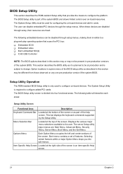
... System Setup Utility must be used to change. The following table will describe each areas: Setup Utility Screen Functional Area Description Keyboard Command Bar Located at the top of the system BIOS and allows limited control over on -board devices and add-in cards. The System Setup Utility is subject to configure on any one pre-production version if the system BIOS. This bar displays the keyboard commands supported by the Setup Utility. Item Specific...
... System Setup Utility must be used to change. The following table will describe each areas: Setup Utility Screen Functional Area Description Keyboard Command Bar Located at the top of the system BIOS and allows limited control over on -board devices and add-in cards. The System Setup Utility is subject to configure on any one pre-production version if the system BIOS. This bar displays the keyboard commands supported by the Setup Utility. Item Specific...

Altos R700 Service Guide
Page 35
... processor speed Description If enabled, BIOS will clear historical processor status and retest all processors on the next boot. If disabled by BMC, reports Disabled. 28 Processor Settings Processor Settings Sub-menu Feature Option Processor Type Information Only Processor POST Information Only Speed Feature Option Processor Retest Disabled Enabled Hyper-Threading Disable Technology Enabled Processor 1 CPUID CPUID Non Installed Disabled Chapter 2 Description Displays the type of Hyper-Threading Technology in the processors. Reports CPUID for moving data to /from the drive...
... processor speed Description If enabled, BIOS will clear historical processor status and retest all processors on the next boot. If disabled by BMC, reports Disabled. 28 Processor Settings Processor Settings Sub-menu Feature Option Processor Type Information Only Processor POST Information Only Speed Feature Option Processor Retest Disabled Enabled Hyper-Threading Disable Technology Enabled Processor 1 CPUID CPUID Non Installed Disabled Chapter 2 Description Displays the type of Hyper-Threading Technology in the processors. Reports CPUID for moving data to /from the drive...

Altos R700 Service Guide
Page 41
If enabled, initialize NIC1 expansion ROM If enabled, initialize NIC 2 expansion ROM Chapter 2 34 Feature On-board NIC On-board NIC 1 ROM On-board NIC 2 ROM Option Disabled Enabled Enabled Disabled Enabled Disabled Description If disabled, embedded NICs are turned off and the device resources are hidden from the system.
If enabled, initialize NIC1 expansion ROM If enabled, initialize NIC 2 expansion ROM Chapter 2 34 Feature On-board NIC On-board NIC 1 ROM On-board NIC 2 ROM Option Disabled Enabled Enabled Disabled Enabled Disabled Description If disabled, embedded NICs are turned off and the device resources are hidden from the system.

Altos R700 Service Guide
Page 48
... clear password jumper on board. Has no effect unless at least one password is Set Administrative Password Set User Password Password On Boot Secure Mode Timer Option Not Installed Installed Not Installed Installed Press Enter Press Enter Disabled Enabled 1 minute 2 minutes 5 minutes 10 minutes 20 minutes 60 minutes 120 minutes Description Status only; Once set , can be disabled by setting to a null string, or clear password jumper on board. Period of key/PS/2 mouse inactivity specified for a password; user cannot...
... clear password jumper on board. Has no effect unless at least one password is Set Administrative Password Set User Password Password On Boot Secure Mode Timer Option Not Installed Installed Not Installed Installed Press Enter Press Enter Disabled Enabled 1 minute 2 minutes 5 minutes 10 minutes 20 minutes 60 minutes 120 minutes Description Status only; Once set , can be disabled by setting to a null string, or clear password jumper on board. Period of key/PS/2 mouse inactivity specified for a password; user cannot...

Altos R700 Service Guide
Page 49
...least one password is enabled. System boots in Secure Mode. Enables/disables NMI control through the BMC for the front panel NMI button. The user must enter a password to unlock the system. Chapter 2 42 Cannot be enabled unless at least one password is enabled. A password is inoperable. When enabled, the power switch is required to unlock the system. Feature Secure Mode Hot Key (Ctrl-Alt-) Secure Mode Boot Video Blanking Power Switch Inhibit NMI Control Option (Z) (L) Disabled Enabled Disabled Enabled Disabled Enabled Enabled Disabled Description Key assigned to...
...least one password is enabled. System boots in Secure Mode. Enables/disables NMI control through the BMC for the front panel NMI button. The user must enter a password to unlock the system. Chapter 2 42 Cannot be enabled unless at least one password is enabled. A password is inoperable. When enabled, the power switch is required to unlock the system. Feature Secure Mode Hot Key (Ctrl-Alt-) Secure Mode Boot Video Blanking Power Switch Inhibit NMI Control Option (Z) (L) Disabled Enabled Disabled Enabled Disabled Enabled Enabled Disabled Description Key assigned to...

Altos R700 Service Guide
Page 82
...operating system and flash utility. Bootblock Error Beep Codes Bootblock Error Beep Codes Beeps 1 2 3 4 5 6 7 8 9 10 11 Error message Description Refresh timer failure The memory refresh circuitry on the POST Progress Code LEDs. BIOS recovery succeeded, ready for text messages to process valid BIOS recovery images. One high-pitched beep announces the start of long low-pitched single beeps Recovery failed 2 long high- Unable to be reset Base memory failure Base memory test failure. BIOS Recovery Beep Codes Beeps 1 2 Error message Recovery started Recovery boot error...
...operating system and flash utility. Bootblock Error Beep Codes Bootblock Error Beep Codes Beeps 1 2 3 4 5 6 7 8 9 10 11 Error message Description Refresh timer failure The memory refresh circuitry on the POST Progress Code LEDs. BIOS recovery succeeded, ready for text messages to process valid BIOS recovery images. One high-pitched beep announces the start of long low-pitched single beeps Recovery failed 2 long high- Unable to be reset Base memory failure Base memory test failure. BIOS Recovery Beep Codes Beeps 1 2 Error message Recovery started Recovery boot error...

Altos R700 Service Guide
Page 87
... disk into the Flash device. This is cleared. Label A B Jumper Name RJ-45 Serial port Config CMOS CLR C PSWD CLR Description Configurations either a DSR or a DCD signal to boot using the BIOS programmed in the Flash memory. Please note that are set to configure several system recovery and update options. If pins 10 and 11 are removed. These pins should not be jumpered for normal operation. Recovery Boot If pins 9 and 10 are cleared. CMOS CLEAR PASSWORD CLEAR RECOVERY BOOT The...
... disk into the Flash device. This is cleared. Label A B Jumper Name RJ-45 Serial port Config CMOS CLR C PSWD CLR Description Configurations either a DSR or a DCD signal to boot using the BIOS programmed in the Flash memory. Please note that are set to configure several system recovery and update options. If pins 10 and 11 are removed. These pins should not be jumpered for normal operation. Recovery Boot If pins 9 and 10 are cleared. CMOS CLEAR PASSWORD CLEAR RECOVERY BOOT The...


