

Power Sd User Guide
Page 7
Replace only with the same or equivalent type recommended by NSTL using the YMark2000 test, and has been found to the manufacturer's instructions. Year 2000 compliance statement The AcerPower Sd computer carries the "Hardware NSTL Tested Year 2000 Compliant" logo, which certifies that this computer is located on the drive. AVOID EXPOSURE TO BEAM. Discard used batteries according to meet NSTL's standards for Year...
Replace only with the same or equivalent type recommended by NSTL using the YMark2000 test, and has been found to the manufacturer's instructions. Year 2000 compliance statement The AcerPower Sd computer carries the "Hardware NSTL Tested Year 2000 Compliant" logo, which certifies that this computer is located on the drive. AVOID EXPOSURE TO BEAM. Discard used batteries according to meet NSTL's standards for Year...

Power Sd User Guide
Page 9
... tips 4 Cleaning and servicing 4 Asking for technical assistance 5 Accessing the online guide 6 2 System tour 7 Features 9 Performance 9 Multimedia 9 Connectivity 9 Front panel 11 Rear panel 13 Keyboard 15 Function keys 16 Lock keys 16 Windows keys 17 Cursor keys 17 Palm rest 17 Volume control/Mute knob 18 Multimedia keys 18 Internet/Suspend keys 19 Programmable keys 19 Mouse 20 Disk drives 21 Floppy drive 21 CD-ROM/DVD-ROM/CD-RW drive 22 Hard disk 24 3 Setting up your computer 25...
... tips 4 Cleaning and servicing 4 Asking for technical assistance 5 Accessing the online guide 6 2 System tour 7 Features 9 Performance 9 Multimedia 9 Connectivity 9 Front panel 11 Rear panel 13 Keyboard 15 Function keys 16 Lock keys 16 Windows keys 17 Cursor keys 17 Palm rest 17 Volume control/Mute knob 18 Multimedia keys 18 Internet/Suspend keys 19 Programmable keys 19 Mouse 20 Disk drives 21 Floppy drive 21 CD-ROM/DVD-ROM/CD-RW drive 22 Hard disk 24 3 Setting up your computer 25...
Power Sd User Guide
Page 10
... 37 Connecting options 38 Printer 38 Serial mouse 40 LCD Monitor 41 Network 42 Multimedia devices 43 USB devices 47 4 Upgrading your computer 49 Installation precautions 51 ESD precautions 51 Preinstallation instructions 51 Post-installation instructions 52 Opening your computer 53 To remove the side panel 53 To replace the side panel 55 Internal components 57 System boards 58 Mainboard 58 Audio board 61 Upgrading your computer 62 Installing additional memory 62 Replacing the hard disk 64 Replacing the CD-ROM/DVD-ROM...
... 37 Connecting options 38 Printer 38 Serial mouse 40 LCD Monitor 41 Network 42 Multimedia devices 43 USB devices 47 4 Upgrading your computer 49 Installation precautions 51 ESD precautions 51 Preinstallation instructions 51 Post-installation instructions 52 Opening your computer 53 To remove the side panel 53 To replace the side panel 55 Internal components 57 System boards 58 Mainboard 58 Audio board 61 Upgrading your computer 62 Installing additional memory 62 Replacing the hard disk 64 Replacing the CD-ROM/DVD-ROM...

Power Sd User Guide
Page 21
... for mouse and keyboard • One serial and one at the same time. By default, your computer's many features: Performance • Intel Pentium® 4 processor • System memory expandable to a maximum of 1GB. • Power management function • 3.5-inch floppy drive • DVD-ROM, CD-ROM or CD-RW drive • High-capacity, Enhanced-IDE hard disk Multimedia • Integrated 256-bit graphics accelerator • 3-D quality audio...
... for mouse and keyboard • One serial and one at the same time. By default, your computer's many features: Performance • Intel Pentium® 4 processor • System memory expandable to a maximum of 1GB. • Power management function • 3.5-inch floppy drive • DVD-ROM, CD-ROM or CD-RW drive • High-capacity, Enhanced-IDE hard disk Multimedia • Integrated 256-bit graphics accelerator • 3-D quality audio...

Power Sd User Guide
Page 47
.... On the rear panel of the computer's rear panel shown below may be different from your computer: 1. If your computer model comes with a main power switch located above the voltage selector switch, first set the voltage selector switch to the voltage range applicable to your computer After connecting the necessary peripherals and plugging in the power cable, you are now ready to work. To turn the computer...
.... On the rear panel of the computer's rear panel shown below may be different from your computer: 1. If your computer model comes with a main power switch located above the voltage selector switch, first set the voltage selector switch to the voltage range applicable to your computer After connecting the necessary peripherals and plugging in the power cable, you are now ready to work. To turn the computer...
Power Sd User Guide
Page 50
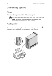
Note: The printers shown below are for your computer Printer Your computer supports parallel, USB and serial printer. Actual device model may vary in select countries. 38 Connecting options 3 Setting up your reference only. Parallel printer To connect a printer, plug the printer cable into the parallel port (burgundy port) located on the rear panel of your computer.
Note: The printers shown below are for your computer Printer Your computer supports parallel, USB and serial printer. Actual device model may vary in select countries. 38 Connecting options 3 Setting up your reference only. Parallel printer To connect a printer, plug the printer cable into the parallel port (burgundy port) located on the rear panel of your computer.

Power Sd User Guide
Page 53
41 LCD Monitor To connect an LCD monitor, plug the LCD monitor's VGA cable into the VGA port (blue port) located on the rear panel of your computer.
41 LCD Monitor To connect an LCD monitor, plug the LCD monitor's VGA cable into the VGA port (blue port) located on the rear panel of your computer.

Power Sd User Guide
Page 54
To do so, simply plug the network cable into the network port on how to a Local Area Network (LAN) using a network cable. Note: Consult your operating system manual for information on the rear panel of your network setup. 42 3 Setting up your computer Network You can connect your computer to configure your computer.
To do so, simply plug the network cable into the network port on how to a Local Area Network (LAN) using a network cable. Note: Consult your operating system manual for information on the rear panel of your network setup. 42 3 Setting up your computer Network You can connect your computer to configure your computer.

Power Sd User Guide
Page 57
45 • external speakers: connect to the Audio-out/Line-out jack (lime jack) located on the rear panel of your computer. • audio line-in device: connects to the Audio-in/Line-in jack (light blue jack) located on the rear panel of your computer.
45 • external speakers: connect to the Audio-out/Line-out jack (lime jack) located on the rear panel of your computer. • audio line-in device: connects to the Audio-in/Line-in jack (light blue jack) located on the rear panel of your computer.
Power Sd User Guide
Page 63
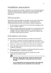
... that block access to the instructions on the component you wish to install. Not turning off your computer and all cables from its protective packaging until you start installing the components may cause serious damage. Remove any procedure requiring ESD protection. See the following sections. Then unplug all the peripherals connected to it before opening it to a metal part of the...
... that block access to the instructions on the component you wish to install. Not turning off your computer and all cables from its protective packaging until you start installing the components may cause serious damage. Remove any procedure requiring ESD protection. See the following sections. Then unplug all the peripherals connected to it before opening it to a metal part of the...
Power Sd User Guide
Page 69
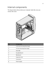
Component 1 5.25-inch drive bays (two bays) 2 3.5-inch drive bays (two bays) 3 Hard disk 4 Daughterboard 5 Mainboard 6 Expansion slots 7 Connectors 8 Power supply 57 Internal components The figure below shows what your computer looks like once you remove the cover: No.
Component 1 5.25-inch drive bays (two bays) 2 3.5-inch drive bays (two bays) 3 Hard disk 4 Daughterboard 5 Mainboard 6 Expansion slots 7 Connectors 8 Power supply 57 Internal components The figure below shows what your computer looks like once you remove the cover: No.

Power Sd User Guide
Page 73
By default, your computer should look like the figure that follows. However, you cannot use both of them at the back. connects to the JUSB1, JUSB2 connector of the mainboard Microphone-in jacks (front and rear). Label JAUD JMIC JSPK JUSB JUSB1 JUSB2 Description Audio connector - connects to the JAUD connector of the mainboard USB ports USB ports Note: The system has two microphone-in jack (front)see note Audio-out port USB connector - 61 Audio board The audio board that came with your system enables the microphone-in jack in front and disables the one at the same time.
By default, your computer should look like the figure that follows. However, you cannot use both of them at the back. connects to the JUSB1, JUSB2 connector of the mainboard Microphone-in jacks (front and rear). Label JAUD JMIC JSPK JUSB JUSB1 JUSB2 Description Audio connector - connects to the JAUD connector of the mainboard USB ports USB ports Note: The system has two microphone-in jack (front)see note Audio-out port USB connector - 61 Audio board The audio board that came with your system enables the microphone-in jack in front and disables the one at the same time.

Power Sd User Guide
Page 74
... is 512-MB which are upgradeable such as the memory, the hard disk, the CPU and the expansion cards. However, for a maximum memory capacity of 2 GB. Contact your dealer or a qualified service technician for qualified DIMM vendors. Note: To capitalize on the mainboard support Double Data Rate (DDR) Synchronous Dynamic Random Access Memory (SDRAM)-type DIMMs. You may install 128-MB, 256-MB...
... is 512-MB which are upgradeable such as the memory, the hard disk, the CPU and the expansion cards. However, for a maximum memory capacity of 2 GB. Contact your dealer or a qualified service technician for qualified DIMM vendors. Note: To capitalize on the mainboard support Double Data Rate (DDR) Synchronous Dynamic Random Access Memory (SDRAM)-type DIMMs. You may install 128-MB, 256-MB...

Power Sd User Guide
Page 76
64 4 Upgrading your computer's hard disk: 1. For more information on BIOS Setup utility, refer to the AcerPower Sd online guide (see page 53). 2. Remove the side panel (see "Accessing the online guide" on page 6). Press the DDR DIMM into the socket, you may have inserted it does not fit easily into the socket until the clips lock onto the DDR DIMM (2,3). Run the BIOS (Basic Input...
64 4 Upgrading your computer's hard disk: 1. For more information on BIOS Setup utility, refer to the AcerPower Sd online guide (see page 53). 2. Remove the side panel (see "Accessing the online guide" on page 6). Press the DDR DIMM into the socket, you may have inserted it does not fit easily into the socket until the clips lock onto the DDR DIMM (2,3). Run the BIOS (Basic Input...

Power Sd User Guide
Page 82
Replace the side panel. Connect all CD/DVD/CD-RW drive cables. 7. 70 4 Upgrading your computer 5. Install a new CD/DVD/CD-RW drive into the drive bay (1) and secure it with two screws you removed earlier (2,3). 6.
Replace the side panel. Connect all CD/DVD/CD-RW drive cables. 7. 70 4 Upgrading your computer 5. Install a new CD/DVD/CD-RW drive into the drive bay (1) and secure it with two screws you removed earlier (2,3). 6.
Power Sd User Guide
Page 84
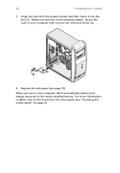
Secure the card to the AcerPower Sd online guide (see page 55). For more information on BIOS, refer to your computer 5. Make sure that the card is properly seated. Replace the side panel (see "Accessing the online guide" on the computer, BIOS automatically detects and assigns resources to the newly-installed devices. Align the card with a screw you turn on page 6). When you removed earlier (2). 6. 72 4 Upgrading your computer with the empty bracket and then insert it into the slot (1).
Secure the card to the AcerPower Sd online guide (see page 55). For more information on BIOS, refer to your computer 5. Make sure that the card is properly seated. Replace the side panel (see "Accessing the online guide" on the computer, BIOS automatically detects and assigns resources to the newly-installed devices. Align the card with a screw you turn on page 6). When you removed earlier (2). 6. 72 4 Upgrading your computer with the empty bracket and then insert it into the slot (1).

Power Sd User Guide
Page 92
... to restore your operating system files are lost or damaged, the recovery process will erase all onscreen instructions until you finish the installation. Remove the System CD and insert the Recovery CD into the CD or DVD drive. 6. Caution! Make sure that the Systems CD/Recovery CD is turned on. 2. Follow all onscreen instructions. 4. Make sure that you to your important files before starting the recovery...
... to restore your operating system files are lost or damaged, the recovery process will erase all onscreen instructions until you finish the installation. Remove the System CD and insert the Recovery CD into the CD or DVD drive. 6. Caution! Make sure that the Systems CD/Recovery CD is turned on. 2. Follow all onscreen instructions. 4. Make sure that you to your important files before starting the recovery...
Power Sd User Guide
Page 95
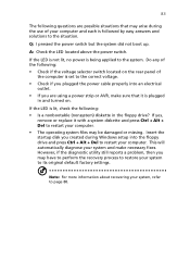
... to its original default factory settings. Do any of the following: • Check if the voltage selector switch located on . However, if the diagnostic utility still reports a problem, then you may be damaged or missing. Q: I pressed the power switch but the system did not boot up. If the LED is set to the correct voltage. • Check if you plugged the power cable properly into an...
... to its original default factory settings. Do any of the following: • Check if the voltage selector switch located on . However, if the diagnostic utility still reports a problem, then you may be damaged or missing. Q: I pressed the power switch but the system did not boot up. If the LED is set to the correct voltage. • Check if you plugged the power cable properly into an...

Power Sd User Guide
Page 99
87 Index A accessing the online guide 6 C computer maintenance 4 cleaning 4 servicing 4 connecting options lcd monitor 41 multimedia devices 43 audio line-in device 45 earphones/headphones 44 external speakers 43 joystick 43 microphone 43 network 38, 42 printer 38 Parallel printer 38 Serial printer 39 USB printer 39 serial mouse 40 D disk drives 21 CD-ROM/DVD-ROM/CD-RW drive inserting CDs/DVDs 22 taking care CDs/DVDs 23 floppy drive 21 not write-protect 21 write...
87 Index A accessing the online guide 6 C computer maintenance 4 cleaning 4 servicing 4 connecting options lcd monitor 41 multimedia devices 43 audio line-in device 45 earphones/headphones 44 external speakers 43 joystick 43 microphone 43 network 38, 42 printer 38 Parallel printer 38 Serial printer 39 USB printer 39 serial mouse 40 D disk drives 21 CD-ROM/DVD-ROM/CD-RW drive inserting CDs/DVDs 22 taking care CDs/DVDs 23 floppy drive 21 not write-protect 21 write...

Power Sd User Guide
Page 100
... boards 58 audio board 61 mainboard 58 T turning off computer 37 software shutdown 37 suspend mode 37 turning on computer 35 Index power button 35 U upgrade add memory 62 install DIMM 63 reconfigure computer 64 computer 62 installation precautions 51 ESD 51 post-installation 52 preinstallation 51 open computer remove side panel 53 replace side panel 55 remove DIMM 63 replace components 62 memory 62 USB devices 47 W Windows logo key Shift +Windows + M 17 Windows + E 17 Windows + F 17 Windows + M 17 Windows + R 17 Windows...
... boards 58 audio board 61 mainboard 58 T turning off computer 37 software shutdown 37 suspend mode 37 turning on computer 35 Index power button 35 U upgrade add memory 62 install DIMM 63 reconfigure computer 64 computer 62 installation precautions 51 ESD 51 post-installation 52 preinstallation 51 open computer remove side panel 53 replace side panel 55 remove DIMM 63 replace components 62 memory 62 USB devices 47 W Windows logo key Shift +Windows + M 17 Windows + E 17 Windows + F 17 Windows + M 17 Windows + R 17 Windows...


