
Power Sp User Guide
Page 2
No part of this publication without obligation to notify any means, electronic, mechanical, photocopy, recording, or otherwise, without the prior written permission of Acer Incorporated. AcerPower SP User's Manual Changes may be incorporated in the space provided below. This company makes no representations or warranties, either expressed or implied, with respect to their respective companies. 1 Other company's product names...
No part of this publication without obligation to notify any means, electronic, mechanical, photocopy, recording, or otherwise, without the prior written permission of Acer Incorporated. AcerPower SP User's Manual Changes may be incorporated in the space provided below. This company makes no representations or warranties, either expressed or implied, with respect to their respective companies. 1 Other company's product names...
Power Sp User Guide
Page 3
.... However, there is likely to result in accordance with the instructions, may cause undesired operation. This device generates, uses, and can radiate radio frequency energy and, if not installed and used in interference to Part 15 of the following measures: • Reorient or relocate the.... FCC notice This device has been tested and found to comply with the limits for help Notice: Shielded cables All connections to other computing devices must accept any interference received, including interference that interference will not occur in a residential installation. These limits are...
.... However, there is likely to result in accordance with the instructions, may cause undesired operation. This device generates, uses, and can radiate radio frequency energy and, if not installed and used in interference to Part 15 of the following measures: • Reorient or relocate the.... FCC notice This device has been tested and found to comply with the limits for help Notice: Shielded cables All connections to other computing devices must accept any interference received, including interference that interference will not occur in a residential installation. These limits are...
Power Sp User Guide
Page 4
... Instructions 12 Post-installation Instructions 13 3.2 Opening your computer 11 3. Replacing the HDD 13 Upgrade the HDD 13 3.3. Necessary to know before Setup 9 Select location 9 Open package 10 2.2. Starting your computer 11 Shutting down your Computer 13 Remove the side panel 13 Replace the side panel 13 3.2. Table Of Content FCC notice 2 1.System Tour 5 1.1 Front panel 5 1.2 Rear panel 5 1.3 System Features 6 Performance 6 Multimedia 6 Connectivity 6 1.4 System peripherals 6 Mouse 7 Keyboard 7 Speakers 7 1.5 System upgrade 8 Open the computer 8 Set...
... Instructions 12 Post-installation Instructions 13 3.2 Opening your computer 11 3. Replacing the HDD 13 Upgrade the HDD 13 3.3. Necessary to know before Setup 9 Select location 9 Open package 10 2.2. Starting your computer 11 Shutting down your Computer 13 Remove the side panel 13 Replace the side panel 13 3.2. Table Of Content FCC notice 2 1.System Tour 5 1.1 Front panel 5 1.2 Rear panel 5 1.3 System Features 6 Performance 6 Multimedia 6 Connectivity 6 1.4 System peripherals 6 Mouse 7 Keyboard 7 Speakers 7 1.5 System upgrade 8 Open the computer 8 Set...

Power Sp User Guide
Page 5
... the drawings in the Guide are diagrams. About components' quantity and style, substances shall take precedence. 4 Taking Care of your computer 19 5.1 Important tips 19 5.2 Cleaning and servicing 19 To clean your computer and keyboard 19 To clean your pointing device 19 To clean your optical mouse 20 To clean your computer 14 3.5. Upgrading CPU 15 Remove CPU 15 Install and upgrade CPU 16 4.
... the drawings in the Guide are diagrams. About components' quantity and style, substances shall take precedence. 4 Taking Care of your computer 19 5.1 Important tips 19 5.2 Cleaning and servicing 19 To clean your computer and keyboard 19 To clean your pointing device 19 To clean your optical mouse 20 To clean your computer 14 3.5. Upgrading CPU 15 Remove CPU 15 Install and upgrade CPU 16 4.
Power Sp User Guide
Page 6
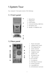
... 2. Headphone Jack 7. USB Connector 10. Game/MIDI Port 15. RJ-45 Ethernet Connector 5 Speaker Jack 8. PCI Card Slot 11. PS/2 Keyboard Port 4. PS/2 Mouse Connector 13. Serial Connector 5. Fan Aperture 12. Printer Connector 14. Microphone Jack 9. Monitor Connector 6. 1.System Tour Your computer's front panel consists of the following: 1.1 Front panel 1.Optical Drive 2.Floppy Drive 3.Power button 4.Universal Serial Bus (USB) Ports 5.Microphone Jack 6.Speaker or Headphone Jack 1.2 Rear panel 1. Voltage selector switch 3.
... 2. Headphone Jack 7. USB Connector 10. Game/MIDI Port 15. RJ-45 Ethernet Connector 5 Speaker Jack 8. PCI Card Slot 11. PS/2 Keyboard Port 4. PS/2 Mouse Connector 13. Serial Connector 5. Fan Aperture 12. Printer Connector 14. Microphone Jack 9. Monitor Connector 6. 1.System Tour Your computer's front panel consists of the following: 1.1 Front panel 1.Optical Drive 2.Floppy Drive 3.Power button 4.Universal Serial Bus (USB) Ports 5.Microphone Jack 6.Speaker or Headphone Jack 1.2 Rear panel 1. Voltage selector switch 3.

Power Sp User Guide
Page 7
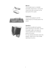
Connectivity Two PS2 ports for keyboard and mouse One serial port One Parallel port One VGA port Four USB 2.0 ports (two on the front, two on the rear panel) High speed V92, 56K fax/Data modem (optional) 10Base-T/100Base-TX Ethernet Network support with "wake on LAN" 1.4 System peripherals The AcerPower SP computer consists the system itself, and system peripherals, like a mouse, a keyboard and a set of basic system peripherals. 6 By default, you system enables your microphone-in jack...
Connectivity Two PS2 ports for keyboard and mouse One serial port One Parallel port One VGA port Four USB 2.0 ports (two on the front, two on the rear panel) High speed V92, 56K fax/Data modem (optional) 10Base-T/100Base-TX Ethernet Network support with "wake on LAN" 1.4 System peripherals The AcerPower SP computer consists the system itself, and system peripherals, like a mouse, a keyboard and a set of basic system peripherals. 6 By default, you system enables your microphone-in jack...
Power Sp User Guide
Page 8
For more detailed information about the speakers, please refer to the PS2 keyboard port on the back panel of the system. Connect the mouse to the audio out (external speaker) port on the back panel of the system. Speakers For systems bundled with speakers, before powering on the system, connect the speaker cable to the PS2 mouse port on the back panel of the system. Mouse The included mouse is a standard two-button wheel mouse. Keyboard Connect the keyboard to the included operating instructions. 7
For more detailed information about the speakers, please refer to the PS2 keyboard port on the back panel of the system. Connect the mouse to the audio out (external speaker) port on the back panel of the system. Speakers For systems bundled with speakers, before powering on the system, connect the speaker cable to the PS2 mouse port on the back panel of the system. Mouse The included mouse is a standard two-button wheel mouse. Keyboard Connect the keyboard to the included operating instructions. 7
Power Sp User Guide
Page 9
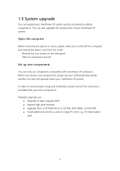
... PCI slots e.g., PCI fax/modem card 8 Slide the panel back and off the computer and unplug the power cord from a CD-ROM drive to High Capacity HDD Expand high-level memory Upgrade from the outlet Remove the two screws on the side panel. 1.5 System upgrade You can expand your new components. Before you choose new components, please ask your authorized Acer dealer whether the part will operate within your AcerPower SP...
... PCI slots e.g., PCI fax/modem card 8 Slide the panel back and off the computer and unplug the power cord from a CD-ROM drive to High Capacity HDD Expand high-level memory Upgrade from the outlet Remove the two screws on the side panel. 1.5 System upgrade You can expand your new components. Before you choose new components, please ask your authorized Acer dealer whether the part will operate within your AcerPower SP...
Power Sp User Guide
Page 10
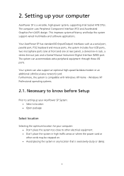
... support varied multimedia and software applications. Your AcerPower SP has standard I /O ports. 2. Setting up your AcerPower SP System: • Select a location • Open package Select location Selecting the optimum location for your computer AcerPower SP is a versatile, high-power system, supporting Intel Socket 478 CPUs. The computer uses Peripheral Component Interface (PCI) and Accelerated Graphics Port (AGP) design. Furthermore, the system is excessively dusty or damp. 9 Necessary to know before Setup...
... support varied multimedia and software applications. Your AcerPower SP has standard I /O ports. 2. Setting up your AcerPower SP System: • Select a location • Open package Select location Selecting the optimum location for your computer AcerPower SP is a versatile, high-power system, supporting Intel Socket 478 CPUs. The computer uses Peripheral Component Interface (PCI) and Accelerated Graphics Port (AGP) design. Furthermore, the system is excessively dusty or damp. 9 Necessary to know before Setup...
Power Sp User Guide
Page 11
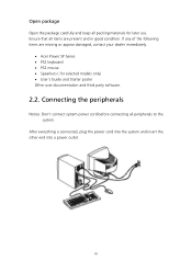
... missing or appear damaged, contact your dealer immediately. • Acer Power SP Series • PS2 keyboard • PS2 mouse • Spearkers ( for later use. If any of the following items are present and in good condition. Open package Open the package carefully and keep all packing materials for selected models only) • User's Guide and Starter poster Other user documentation and third party software. 2.2.
... missing or appear damaged, contact your dealer immediately. • Acer Power SP Series • PS2 keyboard • PS2 mouse • Spearkers ( for later use. If any of the following items are present and in good condition. Open package Open the package carefully and keep all packing materials for selected models only) • User's Guide and Starter poster Other user documentation and third party software. 2.2.
Power Sp User Guide
Page 12
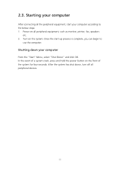
Shutting down , turn off all peripheral devices. 11 Once the start your computer according to use the computer. In the event of a system crash, press and hold the power button on the system. Turn on the front of the system for four seconds. After the system has shut down your computer After connecting all peripheral equipment, such as monitor, printer, fax, speakers etc. 2. Power on all the peripheral equipment, start -up process is complete, you can begin to the below steps: 1. Starting your computer From the "Start" Menu, select "Shut Down" and click OK. 2.3.
Shutting down , turn off all peripheral devices. 11 Once the start your computer according to use the computer. In the event of a system crash, press and hold the power button on the system. Turn on the front of the system for four seconds. After the system has shut down your computer After connecting all peripheral equipment, such as monitor, printer, fax, speakers etc. 2. Power on all the peripheral equipment, start -up process is complete, you can begin to the below steps: 1. Starting your computer From the "Start" Menu, select "Shut Down" and click OK. 2.3.
Power Sp User Guide
Page 13
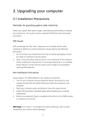
... to install them into computer. 2. Do not remove new components from their protective packaging until you install components, please observe the following precautions: 1. If a wrist grounding strap is not properly shut down before you start to the DIMM sockets or component connectors. ESD Guard ESD can damage the CPU, drives, expansion circuit boards and the other components. Pre-installation Instructions Always...
... to install them into computer. 2. Do not remove new components from their protective packaging until you install components, please observe the following precautions: 1. If a wrist grounding strap is not properly shut down before you start to the DIMM sockets or component connectors. ESD Guard ESD can damage the CPU, drives, expansion circuit boards and the other components. Pre-installation Instructions Always...
Power Sp User Guide
Page 14
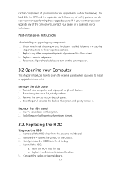
... step instructions in their respective sections. 2. Replace any other components previously removed to the mainboard. 13 Turn off your dealer or a qualified service technician. Replacing the HDD Upgrade the HDD 1. Place the system on the system power. 3.2 Opening your computer are upgradeable such as the memory, the hard disk, the CPU and the expansion card. Connect the cables to allow access. 3. Reconnect all the HDD wires from the drive bay. 4. Gently remove the HDD from...
... step instructions in their respective sections. 2. Replace any other components previously removed to the mainboard. 13 Turn off your dealer or a qualified service technician. Replacing the HDD Upgrade the HDD 1. Place the system on the system power. 3.2 Opening your computer are upgradeable such as the memory, the hard disk, the CPU and the expansion card. Connect the cables to allow access. 3. Reconnect all the HDD wires from the drive bay. 4. Gently remove the HDD from...

Power Sp User Guide
Page 15
... it incorrectly. Remove DDR DIMM 1. Run the BIOS utility to a maximum of memory installed. Press the holding the bracket to the new PCI device. See below. Installing PCI cards Install PCI card 1. Remove the screw holding clips on the motherboard. 2. Secure the card to your computer The system will automatically detect and allocate the resources to back panel and remove the bracket. 3. When you only need to ensure proper installation. Remove PCI card To remove PCI card, you...
... it incorrectly. Remove DDR DIMM 1. Run the BIOS utility to a maximum of memory installed. Press the holding the bracket to the new PCI device. See below. Installing PCI cards Install PCI card 1. Remove the screw holding clips on the motherboard. 2. Secure the card to your computer The system will automatically detect and allocate the resources to back panel and remove the bracket. 3. When you only need to ensure proper installation. Remove PCI card To remove PCI card, you...
Power Sp User Guide
Page 16
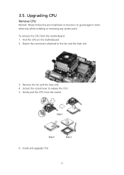
To remove the CPU from the socket. 6. Find the CPU on the motherboard 2. Install and upgrade CPU 15 Remove the fan and the heat sink. 4. Gently pull the CPU from the motherboard: 1. 3.5. Unlock the socket lever to guard against static electricity while installing or removing any system parts. Upgrading CPU Remove CPU Remark: Please follow the pre-installation instructions to release the CPU. 5. Disjoin the connectors attached to the fan and the heat sink. 3.
To remove the CPU from the socket. 6. Find the CPU on the motherboard 2. Install and upgrade CPU 15 Remove the fan and the heat sink. 4. Gently pull the CPU from the motherboard: 1. 3.5. Unlock the socket lever to guard against static electricity while installing or removing any system parts. Upgrading CPU Remove CPU Remark: Please follow the pre-installation instructions to release the CPU. 5. Disjoin the connectors attached to the fan and the heat sink. 3.
Power Sp User Guide
Page 17
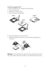
Attach the fan/heat sink on some boards and/or chassis parts. 16 Return the lever to the connectors with marked with "CPU FAN". Attach the fan/heat sink connectors to locked position. 4. Warning! Install the CPU chip into socket. 3. Also, there might be hot if the system has been running. The CPU and heat sink may be sharp pins and edges on top of the CPU. 5. Unlock the socket lever. 2. Install and upgrade CPU To install or upgrade the CPU, complete the following steps: 1.
Attach the fan/heat sink on some boards and/or chassis parts. 16 Return the lever to the connectors with marked with "CPU FAN". Attach the fan/heat sink connectors to locked position. 4. Warning! Install the CPU chip into socket. 3. Also, there might be hot if the system has been running. The CPU and heat sink may be sharp pins and edges on top of the CPU. 5. Unlock the socket lever. 2. Install and upgrade CPU To install or upgrade the CPU, complete the following steps: 1.
Power Sp User Guide
Page 18
... restore your dealer or the technical support center for assistance. 17 A: Check the LED located above the power switch. If yes, remove or replace it is lit, check the following : • Check if the voltage selector switch located on the rear panel of your computer and each is being applied to its original factory default settings. If restarting your computer does not work , your computer. If the LED is plugged...
... restore your dealer or the technical support center for assistance. 17 A: Check the LED located above the power switch. If yes, remove or replace it is lit, check the following : • Check if the voltage selector switch located on the rear panel of your computer and each is being applied to its original factory default settings. If restarting your computer does not work , your computer. If the LED is plugged...
Power Sp User Guide
Page 19
... icon and deselect the Mute option. If your floppy drive, CD or DVD drive can also press the volume control/mute knob on the taskbar. Contact your dealer or technical support center for the Volume icon on your USB keyboard to toggle the mute function. • If headphones, earphones, or external speakers are connected to the printer's documentation. Make sure the diskette, CD or...
... icon and deselect the Mute option. If your floppy drive, CD or DVD drive can also press the volume control/mute knob on the taskbar. Contact your dealer or technical support center for the Volume icon on your USB keyboard to toggle the mute function. • If headphones, earphones, or external speakers are connected to the printer's documentation. Make sure the diskette, CD or...
Power Sp User Guide
Page 20
...not expose the computer to rain or moisture. Never place the system on the plug. Carefully route the power cord and any cables away from personal traffic. When unplugging the power cord, do not pull on the cord itself but pull on uneven surfaces. Do...instructions will help you are using an extension cord. Taking Care of your mouse (with rubber ball) 1) Open the circular cover underneath the mouse. 2) Take out the rubber ball and wipe it near sources of the computer and the keyboard. To clean your pointing device To clean your computer Please read the important instructions listed...
...not expose the computer to rain or moisture. Never place the system on the plug. Carefully route the power cord and any cables away from personal traffic. When unplugging the power cord, do not pull on the cord itself but pull on uneven surfaces. Do...instructions will help you are using an extension cord. Taking Care of your mouse (with rubber ball) 1) Open the circular cover underneath the mouse. 2) Take out the rubber ball and wipe it near sources of the computer and the keyboard. To clean your pointing device To clean your computer Please read the important instructions listed...
Power Sp User Guide
Page 21
... is not operating normally. You may also access the Acer Web site (www.acersupport.com) for technical assistance For technical assistance, contact your screen clean. If liquid has been spilled into the computer. To clean your monitor Make sure that came with your area. 20 3) Put the ball back and replace the cover. To clean your optical mouse For users of an optical mouse, refer...
... is not operating normally. You may also access the Acer Web site (www.acersupport.com) for technical assistance For technical assistance, contact your screen clean. If liquid has been spilled into the computer. To clean your monitor Make sure that came with your area. 20 3) Put the ball back and replace the cover. To clean your optical mouse For users of an optical mouse, refer...


