Service Guide
Page 7
...11 Windows Keys 12 Hot Keys 13 Special Keys 14 Hardware Specifications and Configurations 15 System Utilities 25 BIOS Setup Utility 25 Navigating the BIOS Utility 25 Information 26 Main 27 Security 28 Boot 31 Exit 32 BIOS Flash Utility 33 DOS Flash Utility 34 WinFlash Utility 35 Remove HDD/BIOS Password Utilities 36 Removing BIOS Passwords 37 Miscellaneous Utilities 38 Machine Disassembly and Replacement 41 Disassembly Requirements 41 Related Information 41 Replacement Requirements 41 Pre-disassembly Instructions 42 Disassembly Process 43 External Module Disassembly...
...11 Windows Keys 12 Hot Keys 13 Special Keys 14 Hardware Specifications and Configurations 15 System Utilities 25 BIOS Setup Utility 25 Navigating the BIOS Utility 25 Information 26 Main 27 Security 28 Boot 31 Exit 32 BIOS Flash Utility 33 DOS Flash Utility 34 WinFlash Utility 35 Remove HDD/BIOS Password Utilities 36 Removing BIOS Passwords 37 Miscellaneous Utilities 38 Machine Disassembly and Replacement 41 Disassembly Requirements 41 Related Information 41 Replacement Requirements 41 Pre-disassembly Instructions 42 Disassembly Process 43 External Module Disassembly...
Service Guide
Page 8
... Replacing the I/O Card 108 Replacing the Bluetooth Module 110 Replacing the LED Board 111 Replacing the LCD Module 113 Replacing the Button Board 115 Replacing the Upper Cover 118 Replacing the Keyboard 121 Replacing the Wireless LAN Module 122 Replacing the DIMM Module 124 Replacing the Hard Disk Drive 126 Replacing the Battery 128 Replace the Dummy Card 129 Troubleshooting 131 Common Problems 131 Power On Issue 132 No Display Issue 133 Random Loss of BIOS Settings 134 LCD Failure 135 Built-In Keyboard Failure 136 TouchPad Failure 137 Internal...
... Replacing the I/O Card 108 Replacing the Bluetooth Module 110 Replacing the LED Board 111 Replacing the LCD Module 113 Replacing the Button Board 115 Replacing the Upper Cover 118 Replacing the Keyboard 121 Replacing the Wireless LAN Module 122 Replacing the DIMM Module 124 Replacing the Hard Disk Drive 126 Replacing the Battery 128 Replace the Dummy Card 129 Troubleshooting 131 Common Problems 131 Power On Issue 132 No Display Issue 133 Random Loss of BIOS Settings 134 LCD Failure 135 Built-In Keyboard Failure 136 TouchPad Failure 137 Internal...
Service Guide
Page 12
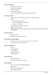
...: • Intel® Wireless WiFi Link 5100 • Acer InviLink™ Nplify™ 802.11b/g/Draft-N • Acer InviLink™ 802.11b/g • LAN: Gigabit Ethernet; Audio subsystem • High-definition audio support • Two built-in stereo speakers • MS-Sound compatible • Built-in -1 card reader (SD/MMC/MS/MS PRO/xD) • USB 2.0 port • HDMI™ port with HDCP support • External display (VGA) port 2 Chapter...
...: • Intel® Wireless WiFi Link 5100 • Acer InviLink™ Nplify™ 802.11b/g/Draft-N • Acer InviLink™ 802.11b/g • LAN: Gigabit Ethernet; Audio subsystem • High-definition audio support • Two built-in stereo speakers • MS-Sound compatible • Built-in -1 card reader (SD/MMC/MS/MS PRO/xD) • USB 2.0 port • HDMI™ port with HDCP support • External display (VGA) port 2 Chapter...
Service Guide
Page 25
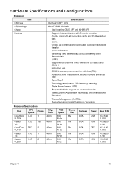
...; Supplemental streaming SIMD extensions 3 (SSSE3) and SSE4.1 • instruction sets. • 800MHz source-synchronous front side bus (FSB) • Advanced power management features including Enhanced Intel • SpeedStep® • Technology and dynamic FSB frequency switching. • Digital thermal sensor (DTS). • Execute disable bit support for enhanced security. • Intel® Dynamic Acceleration Technology and Enhanced Multi • Threaded...
...; Supplemental streaming SIMD extensions 3 (SSSE3) and SSE4.1 • instruction sets. • 800MHz source-synchronous front side bus (FSB) • Advanced power management features including Enhanced Intel • SpeedStep® • Technology and dynamic FSB frequency switching. • Digital thermal sensor (DTS). • Execute disable bit support for enhanced security. • Intel® Dynamic Acceleration Technology and Enhanced Multi • Threaded...
Service Guide
Page 26
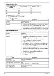
... OS (with independent DMA operation on -board Memory) 2 sockets 2GB 4GB for access to GMCH. • PCI Express Base Specification, Revision 1.1 support. • PCI 2.3 interface. (4 PCI Request/Grant pairs). • ACPI Power Management Logi Support. • Enhanced DMA controller, interrupt controller, timers functions. • Integrated Serial ATA host controllers with two 2GB SO-DIMM) DDR2 Synchronous DRAM 800/667 MHz 16 Chapter 1 CPU Fan True Value Table CPU...
... OS (with independent DMA operation on -board Memory) 2 sockets 2GB 4GB for access to GMCH. • PCI Express Base Specification, Revision 1.1 support. • PCI 2.3 interface. (4 PCI Request/Grant pairs). • ACPI Power Management Logi Support. • Enhanced DMA controller, interrupt controller, timers functions. • Integrated Serial ATA host controllers with two 2GB SO-DIMM) DDR2 Synchronous DRAM 800/667 MHz 16 Chapter 1 CPU Fan True Value Table CPU...

Service Guide
Page 31
... AR8131L device combines pulse shaping, Tx/Rx PCS, echo canceller, NEXT canceller, equalizer, decoder, and timing recovery functions to deliver robust signal performance in noisy environments. • The AR8131L GbE controller supports checksum offload features for IP, TCP, and UDP, Specification ACER NT1T JM11 Black 86/87/91 Yes Yes • Supports application keys for Windows XP version Media Card Reader Chipset Features Item Camera...
... AR8131L device combines pulse shaping, Tx/Rx PCS, echo canceller, NEXT canceller, equalizer, decoder, and timing recovery functions to deliver robust signal performance in noisy environments. • The AR8131L GbE controller supports checksum offload features for IP, TCP, and UDP, Specification ACER NT1T JM11 Black 86/87/91 Yes Yes • Supports application keys for Windows XP version Media Card Reader Chipset Features Item Camera...

Service Guide
Page 35
... arrow keys. • To change boot device without entering BIOS SETUP Utility. Help for a particular menu are found in the Item Specific Help part of screen). You can change the value of the screen. The default parameter of the menu options to go to enter multi-boot menu. System Utilities Chapter 2 BIOS Setup Utility The BIOS Setup Utility is enclosed in square brackets. In this item. • Press Esc while you may need to different models. However, if you encounter configuration problems...
... arrow keys. • To change boot device without entering BIOS SETUP Utility. Help for a particular menu are found in the Item Specific Help part of screen). You can change the value of the screen. The default parameter of the menu options to go to enter multi-boot menu. System Utilities Chapter 2 BIOS Setup Utility The BIOS Setup Utility is enclosed in square brackets. In this item. • Press Esc while you may need to different models. However, if you encounter configuration problems...
Service Guide
Page 37
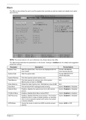
... are displayed with 24hour format. Shows the video memory size. Enables, disables the system boot from LAN (remote server). Main The Main screen allows the user to factory defaults. Information Main InsydeH20 Setup Utility Security Boot Exit System Time: System Date: System Memory: Total Memory: Video Memory: v 1 91:0 : 5 9 v v 0 6 /0099v/ 2 0 640 K 4096 MB v64MBv I t em S p e c i f i cHe l p T h i s i s et hh e l p f otrh e hour field. Valid range i s f r o m t0o 2 3 . INCREASE/EDRUCE: F 5 / Quiet Boot Network Boot F12 Boot Menu D2D Recovery SATA Mode vEnabledv...
... are displayed with 24hour format. Shows the video memory size. Enables, disables the system boot from LAN (remote server). Main The Main screen allows the user to factory defaults. Information Main InsydeH20 Setup Utility Security Boot Exit System Time: System Date: System Memory: Total Memory: Video Memory: v 1 91:0 : 5 9 v v 0 6 /0099v/ 2 0 640 K 4096 MB v64MBv I t em S p e c i f i cHe l p T h i s i s et hh e l p f otrh e hour field. Valid range i s f r o m t0o 2 3 . INCREASE/EDRUCE: F 5 / Quiet Boot Network Boot F12 Boot Menu D2D Recovery SATA Mode vEnabledv...
Service Guide
Page 38
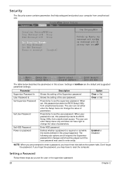
InsydeH20 Setup Utility Information Main Security Boot Exit S u p e r v i s o r P a s s w o r d:I sC l e a r User Password Is: Clear HDD Password Is: Clear S e t S u p e r v i s o r P a s srwd o Set User Password Set Hdd Password Power on password Description Shows the setting of the Supervisor password Shows the setting of parameters. The user can enter Setup menu only and does not have to reset the computer. Defines whether a password is set, this group happened. F1 Help E S C E x it Se l e ct It em F 5 / F 6 C h a n g e V a l u e s F 9 S e t up De f a u l t Se l e ...
InsydeH20 Setup Utility Information Main Security Boot Exit S u p e r v i s o r P a s s w o r d:I sC l e a r User Password Is: Clear HDD Password Is: Clear S e t S u p e r v i s o r P a s srwd o Set User Password Set Hdd Password Power on password Description Shows the setting of the Supervisor password Shows the setting of parameters. The user can enter Setup menu only and does not have to reset the computer. Defines whether a password is set, this group happened. F1 Help E S C E x it Se l e ct It em F 5 / F 6 C h a n g e V a l u e s F 9 S e t up De f a u l t Se l e ...

Service Guide
Page 39
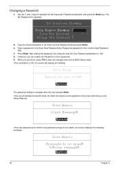
... in the "Enter New Password" field. 1. The Set Password box appears: S e t S u p e r v i s o r P a s sdw o r E n t e r C u r r e n t P a s sdw o r v Enter New Password Confirm New Password v v v 2. Press Enter. Removing a Password Follow these steps: 1. When you have changed the settings, press u to save the changes and exit the BIOS Setup Utility. Type a password in the Enter Current Password field and press Enter. 3. Use the and keys to "Set". 4. Use the and keys to enable the Password on the screen. 3. If desired...
... in the "Enter New Password" field. 1. The Set Password box appears: S e t S u p e r v i s o r P a s sdw o r E n t e r C u r r e n t P a s sdw o r v Enter New Password Confirm New Password v v v 2. Press Enter. Removing a Password Follow these steps: 1. When you have changed the settings, press u to save the changes and exit the BIOS Setup Utility. Type a password in the Enter Current Password field and press Enter. 3. Use the and keys to "Set". 4. Use the and keys to enable the Password on the screen. 3. If desired...
Service Guide
Page 40
.... The Set Password box appears. Setup Notice Changes have been saved. Use the and keys to save the changes and exit the BIOS Setup Utility. vC o n t i n u ev The password setting is OK, the screen will show you can enable the Password on boot parameter. 6. Retype the password in the Enter Current Password field and press Enter. 3. After setting the password, the computer sets the User Password parameter to "Set". 5. Type a password in the Enter New Password field.
.... The Set Password box appears. Setup Notice Changes have been saved. Use the and keys to save the changes and exit the BIOS Setup Utility. vC o n t i n u ev The password setting is OK, the screen will show you can enable the Password on boot parameter. 6. Retype the password in the Enter Current Password field and press Enter. 3. After setting the password, the computer sets the User Password parameter to "Set". 5. Type a password in the Enter New Password field.
Service Guide
Page 46
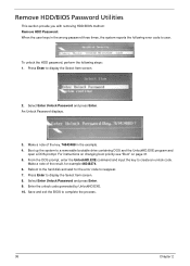
... BIOS to create an unlock code. To unlock the HDD password, perform the following error code to display the Select Item screen. 8. Boot up the system to display the Select Item screen. 2. Make a note of the key, 76943488 in the wrong password three times, the system reports the following steps: 1. Press Enter to a removable bootable drive containing DOS and the UnlockHD.EXE program and open a DOS prompt. Press Enter to user. Remove HDD/BIOS Password Utilities...
... BIOS to create an unlock code. To unlock the HDD password, perform the following error code to display the Select Item screen. 8. Boot up the system to display the Select Item screen. 2. Make a note of the key, 76943488 in the wrong password three times, the system reports the following steps: 1. Press Enter to a removable bootable drive containing DOS and the UnlockHD.EXE program and open a DOS prompt. Press Enter to user. Remove HDD/BIOS Password Utilities...
Service Guide
Page 141
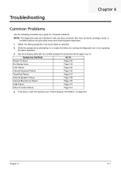
...) Go To Power On Issue Page 132 No Display Issue Page 133 LCD Failure Page 135 Internal Keyboard Failure Page 136 TouchPad Failure Page 137 Internal Speaker Failure Page 138 Internal Microphone Failure Page 139 USB Failure Page 141 Other Function Failure Page 141 4. If the Issue is still not resolved, see "Online Support Information" on page 241. Troubleshooting Chapter 4 Common Problems Use the following table...
...) Go To Power On Issue Page 132 No Display Issue Page 133 LCD Failure Page 135 Internal Keyboard Failure Page 136 TouchPad Failure Page 137 Internal Speaker Failure Page 138 Internal Microphone Failure Page 139 USB Failure Page 141 Other Function Failure Page 141 4. If the Issue is still not resolved, see "Online Support Information" on page 241. Troubleshooting Chapter 4 Common Problems Use the following table...
Service Guide
Page 143
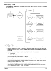
... occurs: • Fans start up • Status LEDs light up If there is done by pressing Fn+F5 (on page 135. 5. On this model). Drain any memory cards and CD/DVD discs. Disconnect power and all external devices including port replicators or docking stations. No troubleshooting step Ext. Make sure that the internal display is by pressing Fn+F5. Connect an external monitor to the computer...
... occurs: • Fans start up • Status LEDs light up If there is done by pressing Fn+F5 (on page 135. 5. On this model). Drain any memory cards and CD/DVD discs. Disconnect power and all external devices including port replicators or docking stations. No troubleshooting step Ext. Make sure that the internal display is by pressing Fn+F5. Connect an external monitor to the computer...

Service Guide
Page 144
... brightness setting, the LCD is properly installed. d. If HDD information is not running on page 43. 4. Remove the drives (see "Online Support Information" on adjusting settings. See "Disassembly Process" on battery alone as this may be defective and should be replaced. If the computer is correctly configured: a. Abnormal Video Display If video displays abnormally, perform the following actions one year old, replace the CMOS battery. 2. Run the Windows Memory Diagnostic from the BIOS, the drive...
... brightness setting, the LCD is properly installed. d. If HDD information is not running on page 43. 4. Remove the drives (see "Online Support Information" on adjusting settings. See "Disassembly Process" on battery alone as this may be defective and should be replaced. If the computer is correctly configured: a. Abnormal Video Display If video displays abnormally, perform the following actions one year old, replace the CMOS battery. 2. Run the Windows Memory Diagnostic from the BIOS, the drive...
Service Guide
Page 148
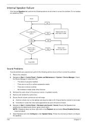
... correct the problem. 1. Roll back the audio driver to Start Control Panel Hardware and Sound Sound. Ensure that Speakers are no red Xs or yellow exclamation marks. • There are selected as the default audio device (green check mark). Reboot the computer. 2. Navigate to the previous version, if updated recently. 4. Check the Device Manager to 50 and not muted. 6. Remove and reinstall the audio driver. 5. Ensure...
... correct the problem. 1. Roll back the audio driver to Start Control Panel Hardware and Sound Sound. Ensure that Speakers are no red Xs or yellow exclamation marks. • There are selected as the default audio device (green check mark). Reboot the computer. 2. Navigate to the previous version, if updated recently. 4. Check the Device Manager to 50 and not muted. 6. Remove and reinstall the audio driver. 5. Ensure...
Service Guide
Page 149
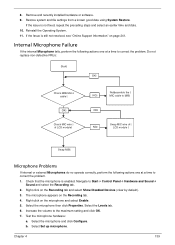
... good date using System Restore. cable OK Check MIC wire of LCD module Re-assemble the NG MIC cable to M/B OK Swap MIC wire of NG LCD module Swap M/B Microphone Problems If internal or external Microphones do no operate correctly, perform the following actions one at a time to correct the problem. 1. Test the microphone hardware: a. Chapter 4 139 Reinstall the Operating System. 11. Right-click on the microphone and select Enable. 5. If...
... good date using System Restore. cable OK Check MIC wire of LCD module Re-assemble the NG MIC cable to M/B OK Swap MIC wire of NG LCD module Swap M/B Microphone Problems If internal or external Microphones do no operate correctly, perform the following actions one at a time to correct the problem. 1. Test the microphone hardware: a. Chapter 4 139 Reinstall the Operating System. 11. Right-click on the microphone and select Enable. 5. If...
Service Guide
Page 150
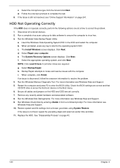
... cables and jumpers on the HDD and ODD are set as the first boot device on the Boot menu. 6. Click Next. The System Recovery Options screen displays. Select Startup Repair. When complete, click Finish. For more information see Windows Help and Support. 5. Remove any key to start to the operating system DVD. Restore system and file settings from the list and click Next. Run a complete virus scan using System Restore. h. Startup Repair attempts to enter the BIOS Utility. d. f. Replace...
... cables and jumpers on the HDD and ODD are set as the first boot device on the Boot menu. 6. Click Next. The System Recovery Options screen displays. Select Startup Repair. When complete, click Finish. For more information see Windows Help and Support. 5. Remove any key to start to the operating system DVD. Restore system and file settings from the list and click Next. Run a complete virus scan using System Restore. h. Startup Repair attempts to enter the BIOS Utility. d. f. Replace...
Service Guide
Page 152
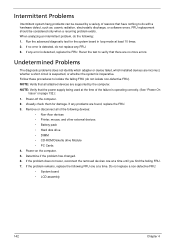
... the problem remains, replace the following devices: • Non-Acer devices • Printer, mouse, and other external devices • Battery pack • Hard disk drive • DIMM • CD-ROM/Diskette drive Module • PC Cards 4. Visually check them for the system board in loop mode at a time until you find the failing FRU. 7. Undetermined Problems The diagnostic problems does not identify which adapter or device failed, which installed devices are found, replace the...
... the problem remains, replace the following devices: • Non-Acer devices • Printer, mouse, and other external devices • Battery pack • Hard disk drive • DIMM • CD-ROM/Diskette drive Module • PC Cards 4. Visually check them for the system board in loop mode at a time until you find the failing FRU. 7. Undetermined Problems The diagnostic problems does not identify which adapter or device failed, which installed devices are found, replace the...
Service Guide
Page 254
... Disassembly Flowchart 54 Mainboard Removing 71 media access on indicator 9 Memory Check 132 Microphone Removing 83, 95 Model Definition 161 N No Display Issue 133 num lock on indicator 9 O ODD Failure 141 Online Support Information 241 P Panel 5 left 5 PC Card 9 Power On Failure 132 S Speaker Module Removing 68 speakers hotkey 13 System Block Diagram 4 T Test Compatible Components 231 Thermal Module Removing 74 Touch Pad Failure 137 Troubleshooting Built-in KB Failure 136 Internal Microphone 139 244 Internal Speakers 138 LCD...
... Disassembly Flowchart 54 Mainboard Removing 71 media access on indicator 9 Memory Check 132 Microphone Removing 83, 95 Model Definition 161 N No Display Issue 133 num lock on indicator 9 O ODD Failure 141 Online Support Information 241 P Panel 5 left 5 PC Card 9 Power On Failure 132 S Speaker Module Removing 68 speakers hotkey 13 System Block Diagram 4 T Test Compatible Components 231 Thermal Module Removing 74 Touch Pad Failure 137 Troubleshooting Built-in KB Failure 136 Internal Microphone 139 244 Internal Speakers 138 LCD...


