
AL532 Monitor Service Guide
Page 2
CONTROL LOCATION 5 E. ADJUSTMENT PROCEDURE 10 G. TROUBLE SHOOTING HINTS 11 H. BLOCK DIAGRAM 21 J. IMPORTANT SAFETY INSTRUCTION∙∙∙ 1 B. SCHEMATIC DIAGRAM 22 TABLE OF CONTENTS SERVICE WARNING 1 A. REPLACEMENT PARTS LIST 15 I. CONDUCTION VIEW 6 F. TIMING CHART 3 D. SPECIFICATIONS 2 C.
CONTROL LOCATION 5 E. ADJUSTMENT PROCEDURE 10 G. TROUBLE SHOOTING HINTS 11 H. BLOCK DIAGRAM 21 J. IMPORTANT SAFETY INSTRUCTION∙∙∙ 1 B. SCHEMATIC DIAGRAM 22 TABLE OF CONTENTS SERVICE WARNING 1 A. REPLACEMENT PARTS LIST 15 I. CONDUCTION VIEW 6 F. TIMING CHART 3 D. SPECIFICATIONS 2 C.
AL532 Monitor Service Guide
Page 3
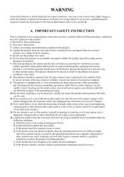
... change in performance,indicating a need help. e. WARNING To prevent from overheating,those controls that you have carefully followed all the procedures outlined in the user's manual for this product. 1. A. Do not use a damp cloth for cleaning. 5. Do not allow anything to rest on the power cord.Do not locate this product where persons will often require extension work by the operating instructions...
... change in performance,indicating a need help. e. WARNING To prevent from overheating,those controls that you have carefully followed all the procedures outlined in the user's manual for this product. 1. A. Do not use a damp cloth for cleaning. 5. Do not allow anything to rest on the power cord.Do not locate this product where persons will often require extension work by the operating instructions...
AL532 Monitor Service Guide
Page 4
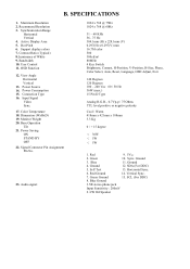
Synchronization Range Horizontal Vertical 4. Support display colors 7. Connection Type 16. Signal Connector Pin Assignment Pin No. 23. SDA (For DDC) 5. Horizontal Sync. 6. Green Ground 15. SPECIFICATIONS 1. Active Display Area 5. View Angle Horizontal Vertical 13. Monitor Weight 20. Green 10. Ground 3. Self Test 13. Recommend Resolution 3. Dot Pitch 6. Power Consumption 15. Vertical Sync. 7. Bandwidth 10. Input Signal Video Sync. 17. Base Operation Tilt 21. Blue 11. Dimension (WxHxD) 19. Audio signal 1024 x 768 @ 75Hz 1024 x 768 @ 60Hz 31 - 60 KHz 56...
Synchronization Range Horizontal Vertical 4. Support display colors 7. Connection Type 16. Signal Connector Pin Assignment Pin No. 23. SDA (For DDC) 5. Horizontal Sync. 6. Green Ground 15. SPECIFICATIONS 1. Active Display Area 5. View Angle Horizontal Vertical 13. Monitor Weight 20. Green 10. Ground 3. Self Test 13. Recommend Resolution 3. Dot Pitch 6. Power Consumption 15. Vertical Sync. 7. Bandwidth 10. Input Signal Video Sync. 17. Base Operation Tilt 21. Blue 11. Dimension (WxHxD) 19. Audio signal 1024 x 768 @ 75Hz 1024 x 768 @ 60Hz 31 - 60 KHz 56...
AL532 Monitor Service Guide
Page 12
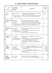
...;0.2V Power Saving ﹟Wattmeter Check ﹟PC or Pattern B generator ﹫Crosshatch Pattern (31.5KHz,640x480) 1. Make sure the voltage of the monitor ON. 3. set color is 9300°K using the OSD,Check the value y = 0.297 shown at right. 5. OSD will be display "NO SIGNAL" Picture. ‹ 5W Into Factory mode C ﹟PC or Pattern generator ﹫Crosshatch Pattern (31.5KHz,640x480) 1. F. Plug power cable into the adapter, check adapter power indicator light...
...;0.2V Power Saving ﹟Wattmeter Check ﹟PC or Pattern B generator ﹫Crosshatch Pattern (31.5KHz,640x480) 1. Make sure the voltage of the monitor ON. 3. set color is 9300°K using the OSD,Check the value y = 0.297 shown at right. 5. OSD will be display "NO SIGNAL" Picture. ‹ 5W Into Factory mode C ﹟PC or Pattern generator ﹫Crosshatch Pattern (31.5KHz,640x480) 1. F. Plug power cable into the adapter, check adapter power indicator light...
AL532 Monitor Service Guide
Page 13
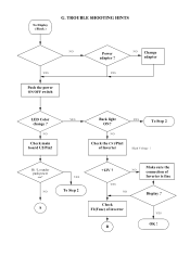
TROUBLE SHOOTING HINTS LED ON ? NO A YES To Step 2 +12V ? Hi / Lo under push power sw? NO YES NO Check F1(Fuse) of inverter B Make sure the connection of Inverter High Voltage ! YES NO Change adapter LED Color change ? YES OK ! NO Check the CN1/Pin1 of Inverter is fine Display ? NO Check main board U2/Pin2 YES Back light YES To Step 2 ON? NO YES Push the power ON/OFF switch Power adapter ? No Display ( Black ) G.
TROUBLE SHOOTING HINTS LED ON ? NO A YES To Step 2 +12V ? Hi / Lo under push power sw? NO YES NO Check F1(Fuse) of inverter B Make sure the connection of Inverter High Voltage ! YES NO Change adapter LED Color change ? YES OK ! NO Check the CN1/Pin1 of Inverter is fine Display ? NO Check main board U2/Pin2 YES Back light YES To Step 2 ON? NO YES Push the power ON/OFF switch Power adapter ? No Display ( Black ) G.
AL532 Monitor Service Guide
Page 15
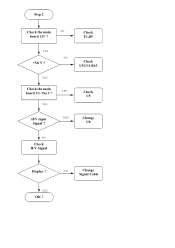
YES Change U8 NO Check H/V Signal Display ? YES Check the main YES board U5 / Pin 3 ? NO Change Signal Cable YES OK ! YES Check U9,U11,R43 Check U5 H/V input Signal ? Step 2 Check the main NO board 12V ? Check F1,D5 YES NO +5.0 V ?
YES Change U8 NO Check H/V Signal Display ? YES Check the main YES board U5 / Pin 3 ? NO Change Signal Cable YES OK ! YES Check U9,U11,R43 Check U5 H/V input Signal ? Step 2 Check the main NO board 12V ? Check F1,D5 YES NO +5.0 V ?
AL532 Monitor Service Guide
Page 16
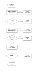
YES OK ! NO Check U7,U12 YES NO Check the main Check board U8/Pin1 ? 3.3V Circuit YES H/V Input Signal ? NO Check H/V Signal YES Change U8 Display ? No display (White) Check the main NO Check board 5V ? U9,U11,R43 YES +3.3V ? NO Change Signal Cable
YES OK ! NO Check U7,U12 YES NO Check the main Check board U8/Pin1 ? 3.3V Circuit YES H/V Input Signal ? NO Check H/V Signal YES Change U8 Display ? No display (White) Check the main NO Check board 5V ? U9,U11,R43 YES +3.3V ? NO Change Signal Cable
AL532 Monitor Service Guide
Page 17
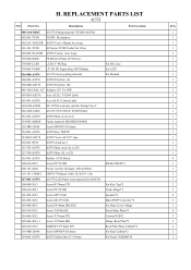
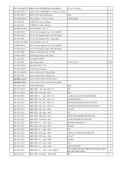
... For Panel C02RD0534 1 H. Control PCB*2 2 105-006-4033-1 Screw T4*6mm ISO Hinge+Rear Plate*2 2 105-010-3012 SCREW T3*10mm TP1. REPLACEMENT PARTS LIST AL532 NO Parts No. For LCD 1 826-000-AS576 AS-576 Series pcking material For Manual 1 160-00L-AS576 AS576 Polyfom (L). 1 160-00R-AS576 AS576 Polyfom (R). 1 846-120-C0AL-AT Adapter 12V 3A 36W 1 003-H01-AS576 Acer AL532...
... For Panel C02RD0534 1 H. Control PCB*2 2 105-006-4033-1 Screw T4*6mm ISO Hinge+Rear Plate*2 2 105-010-3012 SCREW T3*10mm TP1. REPLACEMENT PARTS LIST AL532 NO Parts No. For LCD 1 826-000-AS576 AS-576 Series pcking material For Manual 1 160-00L-AS576 AS576 Polyfom (L). 1 160-00R-AS576 AS576 Polyfom (R). 1 846-120-C0AL-AT Adapter 12V 3A 36W 1 003-H01-AS576 Acer AL532...
AL532 Monitor Service Guide
Page 18
...Audio Cable 3.5Ø STERE0 to 2*RCA connector 1 631-006-7020-T SH570/770 1061#28 6P2.0mm EMI 1 631-008-G020-W 8Pin 1.5Pitch 8Pin 1.5Pitch CTR/B->M/B 1 631-030-F576 30 PIN FFC Cable L182mm 1 631-040-F576 40 PIN FFC Cable L193mm 1 824-00Q-AY565L AY565 Speaker Ass'y L 1 154-000-SPCS AY/CY Series Speaker.... 1 600-151-5004-M Power Cord for UK 150cm White 1 600-151-5504 Power Crd for Swiss 150cm 白色. 1 899-00M-AS576 AS576 Main PCB for SANYO Panel 1 852-00M-AS576 AS576 Main PCB for SANYO Panel SMD 1 200-100-AS576 AS576 Main Board PCB 1 281-031-20014 ...
...Audio Cable 3.5Ø STERE0 to 2*RCA connector 1 631-006-7020-T SH570/770 1061#28 6P2.0mm EMI 1 631-008-G020-W 8Pin 1.5Pitch 8Pin 1.5Pitch CTR/B->M/B 1 631-030-F576 30 PIN FFC Cable L182mm 1 631-040-F576 40 PIN FFC Cable L193mm 1 824-00Q-AY565L AY565 Speaker Ass'y L 1 154-000-SPCS AY/CY Series Speaker.... 1 600-151-5004-M Power Cord for UK 150cm White 1 600-151-5504 Power Crd for Swiss 150cm 白色. 1 899-00M-AS576 AS576 Main PCB for SANYO Panel 1 852-00M-AS576 AS576 Main PCB for SANYO Panel SMD 1 200-100-AS576 AS576 Main Board PCB 1 281-031-20014 ...
AL532 Monitor Service Guide
Page 20
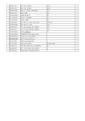
...SCP606 CN10 1 504-000-6300L Reset IC. V6300L TO92 (DIP) TU2...X2 1 630-002-1008 Base Pitch 2.0 2Pin JWT A2001 CN7,CN8 2 630-006-4002R Base Pitch 2.0 6Pin CN5 1... 630-008-C001 JST 1.5mm Header ZR S8B-ZR CN2 1 745-050-3072 Line Coil 5uH JBT0385 100805-4 L19 1 745-470-20621 Choke 47UH@3A L7 1 152-000-SH570 TOSHIBA DC Jack Support Nylon. 1 849-40X-AS576 Inverter 2 to 4 8ma E-MAX 1 899-400-AS576 AS-576 Control... PCB Ass'y. 1 200-701-0576 AS576 Control Key PCB 1 401-170-0220 Tact Switch H5mm S1,S2,S3,S4,S5 5 520-005-L937 LED 2Pin Blue...
...SCP606 CN10 1 504-000-6300L Reset IC. V6300L TO92 (DIP) TU2...X2 1 630-002-1008 Base Pitch 2.0 2Pin JWT A2001 CN7,CN8 2 630-006-4002R Base Pitch 2.0 6Pin CN5 1... 630-008-C001 JST 1.5mm Header ZR S8B-ZR CN2 1 745-050-3072 Line Coil 5uH JBT0385 100805-4 L19 1 745-470-20621 Choke 47UH@3A L7 1 152-000-SH570 TOSHIBA DC Jack Support Nylon. 1 849-40X-AS576 Inverter 2 to 4 8ma E-MAX 1 899-400-AS576 AS-576 Control... PCB Ass'y. 1 200-701-0576 AS576 Control Key PCB 1 401-170-0220 Tact Switch H5mm S1,S2,S3,S4,S5 5 520-005-L937 LED 2Pin Blue...
AL532 User Guide
Page 1
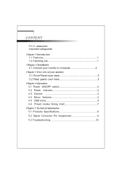
CONTENT F.C.C. statement Important safeguards Chapter 1 Introduction 1.1 Features 1 1.2 Checking List 1 Chapter 2 Installation 2.1 Connect your monitor to computer 2 Chapter 3 Over view of your monitor 3.1 Front Panel over view 3 3.2 Rear panel over view 3 Chapter 4 Operation 4.1 Power ON/OFF switch 4 4.2 Power indicator 4 4.3 Volume 4 4.4 Menu features 4 4.5 OSD menu 5 4.6 Preset modes timing chart 7 Chapter 5 Technical information 5.1 Products Specifications 8 5.2 Signal Connector Pin Assignment 9 5.3 Troubleshooting 10
CONTENT F.C.C. statement Important safeguards Chapter 1 Introduction 1.1 Features 1 1.2 Checking List 1 Chapter 2 Installation 2.1 Connect your monitor to computer 2 Chapter 3 Over view of your monitor 3.1 Front Panel over view 3 3.2 Rear panel over view 3 Chapter 4 Operation 4.1 Power ON/OFF switch 4 4.2 Power indicator 4 4.3 Volume 4 4.4 Menu features 4 4.5 OSD menu 5 4.6 Preset modes timing chart 7 Chapter 5 Technical information 5.1 Products Specifications 8 5.2 Signal Connector Pin Assignment 9 5.3 Troubleshooting 10
AL532 User Guide
Page 2
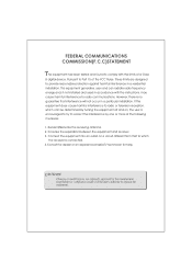
... can radiate radio frequency energy and, if not installed and used in accordance with the limits of a Class B digital device. Increase the separation between the equipment and receiver. 3. This equipment generates, uses and can be...installation. FEDERAL COMMUNICATIONS COMMISSION(F.C.C)STATEMENT This equipment has been tested and found to Part 15 of the FCC Rules. Connect the equipment into an outlet on , the user is connected. 4.Consult the dealer or an experienced radio/TV technician for help. Reorient/Relocate the receiving antenna. 2. Pursuant to comply with the instructions...
... can radiate radio frequency energy and, if not installed and used in accordance with the limits of a Class B digital device. Increase the separation between the equipment and receiver. 3. This equipment generates, uses and can be...installation. FEDERAL COMMUNICATIONS COMMISSION(F.C.C)STATEMENT This equipment has been tested and found to Part 15 of the FCC Rules. Connect the equipment into an outlet on , the user is connected. 4.Consult the dealer or an experienced radio/TV technician for help. Reorient/Relocate the receiving antenna. 2. Pursuant to comply with the instructions...
AL532 User Guide
Page 3
...'s instructions, and should never be blocked by persons working on it from the wall outlet before cleaning. The openings should use liquid cleaners or aerosol cleaners. This monitor should never be blocked or covered. f. The monitor may touch dangerous voltage points or short out parts that could result in the cabinet and the back or bottom are provided for cleaning. 3. When the power cord...
...'s instructions, and should never be blocked by persons working on it from the wall outlet before cleaning. The openings should use liquid cleaners or aerosol cleaners. This monitor should never be blocked or covered. f. The monitor may touch dangerous voltage points or short out parts that could result in the cabinet and the back or bottom are provided for cleaning. 3. When the power cord...
AL532 User Guide
Page 4
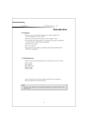
... power supply. RMicrosoft windows 9x/2000 compatible & VESA Display Data Channel (DDC)1/2B compatible. 1.2 Checking List Please make sure the following items are included with your dealer for technical support and customer service. Note: 1 Introduction Chapter 1 Introduction 1.1 Features RMulti-scanning at horizontal frequencies of 31KHz to 60KHz and vertical frequencies of these items are missing ,please contact with OSD (On Screen Display) control. RMicroprocessor based with your LCD monitor: RYour monitor RAC Adapter RAC Power cord...
... power supply. RMicrosoft windows 9x/2000 compatible & VESA Display Data Channel (DDC)1/2B compatible. 1.2 Checking List Please make sure the following items are included with your dealer for technical support and customer service. Note: 1 Introduction Chapter 1 Introduction 1.1 Features RMulti-scanning at horizontal frequencies of 31KHz to 60KHz and vertical frequencies of these items are missing ,please contact with OSD (On Screen Display) control. RMicroprocessor based with your LCD monitor: RYour monitor RAC Adapter RAC Power cord...

AL532 User Guide
Page 5
Plug the computer and monitor power cables into a nearby outlet. 5. If the monitor does not display an image ,check all the connections. Turn off your monitor display an image , you have successfully installed the monitor. Turn your computer and monitor on , if your computer and unplug its power cable. 2. Chapter 2 Installation Installation 2.1 Connect your computer. 3. You must use the supplied adapter. 4. Connect the signal cable to the video port on the back of your monitor to computer 1. Connecting the monitor to the DC adapter and...
Plug the computer and monitor power cables into a nearby outlet. 5. If the monitor does not display an image ,check all the connections. Turn off your monitor display an image , you have successfully installed the monitor. Turn your computer and monitor on , if your computer and unplug its power cable. 2. Chapter 2 Installation Installation 2.1 Connect your computer. 3. You must use the supplied adapter. 4. Connect the signal cable to the video port on the back of your monitor to computer 1. Connecting the monitor to the DC adapter and...
AL532 User Guide
Page 7
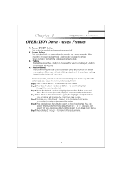
... to make further adjustments. 4 Press and release Menu Button again to store the change the color from pink to turn the monitor on screen menu system. Press to decrease the volume . This indicator lights up green when the monitor op erates normally. Once are finished. Also you can all be accessed using your adjustment , press < or > clockwise to increase or counterclockwise to turn off . Chapter 4 OPERATION Direct - Making adjustments...
... to make further adjustments. 4 Press and release Menu Button again to store the change the color from pink to turn the monitor on screen menu system. Press to decrease the volume . This indicator lights up green when the monitor op erates normally. Once are finished. Also you can all be accessed using your adjustment , press < or > clockwise to increase or counterclockwise to turn off . Chapter 4 OPERATION Direct - Making adjustments...
AL532 User Guide
Page 8
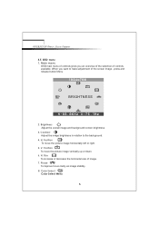
... Access Features 1. Position To move the picture image vertically up or down. 6. Phase To improve focus clarity an image stability. 8. Contrast Adjust the image brightness in relation to make adjustment of the screen Image , press and release button Menu BRIGHTNESS 2. H. Size To increase or decrease the horizontal size of controls available. Brightness Adjust the overall image and background screen brightness. 3. H. Color Select Color Select Menu 5 Position To move the picture image horizontally left or right. 5. Main menu OSD main menu of controls gives you want...
... Access Features 1. Position To move the picture image vertically up or down. 6. Phase To improve focus clarity an image stability. 8. Contrast Adjust the image brightness in relation to make adjustment of the screen Image , press and release button Menu BRIGHTNESS 2. H. Size To increase or decrease the horizontal size of controls available. Brightness Adjust the overall image and background screen brightness. 3. H. Color Select Color Select Menu 5 Position To move the picture image horizontally left or right. 5. Main menu OSD main menu of controls gives you want...
AL532 User Guide
Page 9
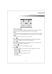
... OSD image vertically up or down. Increase or decrease red .green or blue depending upon Which color is bluer and brighter. This control adjusts the color temperature of the display image needs further adjustment . 10. Auto Auto adjust display mode to its utmost performance according to the factory setting . Reset Reset the currently highlighted control to VGA setting. The performance is redder and closer to individual color gum intensity by factory , you need. 12. Exit : To exit the sub menu 6 User...
... OSD image vertically up or down. Increase or decrease red .green or blue depending upon Which color is bluer and brighter. This control adjusts the color temperature of the display image needs further adjustment . 10. Auto Auto adjust display mode to its utmost performance according to the factory setting . Reset Reset the currently highlighted control to VGA setting. The performance is redder and closer to individual color gum intensity by factory , you need. 12. Exit : To exit the sub menu 6 User...
AL532 User Guide
Page 11
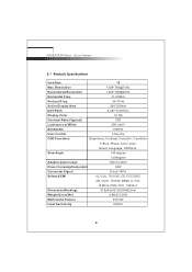
...@75Hz Recommend Resolution 1024*768@60Hz Horizontal Freq. 31-60KHz Vertucal Freq. 56-75Hz Active Display Area 304*228mm DOT Pitch 0.297*0.297mm Display Color 16.7M Contrast Ratio (Typical) 500 Luminance of White 300 cd/m2 Bandwidth 80MHz User Control 4 Key Sw OSD Functions Brightness, Contrast, H-positin, V-position H-Size, Phase, Color, Auto, Reset, Language, OSD,Exit, View Angle 140 degree 120degree Adapter power input 100V to 240V Power Consumption(under) 36W Connector Signal D-sub 15Pin...
...@75Hz Recommend Resolution 1024*768@60Hz Horizontal Freq. 31-60KHz Vertucal Freq. 56-75Hz Active Display Area 304*228mm DOT Pitch 0.297*0.297mm Display Color 16.7M Contrast Ratio (Typical) 500 Luminance of White 300 cd/m2 Bandwidth 80MHz User Control 4 Key Sw OSD Functions Brightness, Contrast, H-positin, V-position H-Size, Phase, Color, Auto, Reset, Language, OSD,Exit, View Angle 140 degree 120degree Adapter power input 100V to 240V Power Consumption(under) 36W Connector Signal D-sub 15Pin...
AL532 User Guide
Page 13
... the wall outlet. There is no sound or sound is low u Check the sound cable connection u Make sure the computer sound program is too light or too dark u Use OSD controls to adjust AuTo SETup. u Adjust the volume control keys on sound setting. There is no SCREEN image u The power cord is too large or small u Use the OSD controls to adjust the brightness and contrast. The image is working u Adjust the volume on the monitor 10 Monitor in this section to adjust the color control setting. u Check the signal cable connection between the monitor and...
... the wall outlet. There is no sound or sound is low u Check the sound cable connection u Make sure the computer sound program is too light or too dark u Use OSD controls to adjust AuTo SETup. u Adjust the volume control keys on sound setting. There is no SCREEN image u The power cord is too large or small u Use the OSD controls to adjust the brightness and contrast. The image is working u Adjust the volume on the monitor 10 Monitor in this section to adjust the color control setting. u Check the signal cable connection between the monitor and...

