
AL1751 Service Guide
Page 5
... equipment. Dangerously high voltages are designed to Part 15 of the following measures: 1. These limits are present inside the monitor. Shielded interface cables and AC power cord, if any radio or TV interference caused by the party responsible for a Class B digital device, pursuant to provide reasonable protection against harmful interference in...
... equipment. Dangerously high voltages are designed to Part 15 of the following measures: 1. These limits are present inside the monitor. Shielded interface cables and AC power cord, if any radio or TV interference caused by the party responsible for a Class B digital device, pursuant to provide reasonable protection against harmful interference in...
AL1751 Service Guide
Page 6
...on a wall or shelf, use a mounting kit approved by the manufacturer or sold with a third (grounding) pin. If your dealer or local power company. Never spill liquids on an unstable trolley, stand, or table. Slots and openings in the back and bottom of the grounded plug. opening... safety purpose of the cabinet are not blocked or covered. The monitor should be sure these openings are provided for long periods of power supplied to the appliance. Do not attempt to ground the appliance safely. The wall socket shall be used for ventilation. If the ...
...on a wall or shelf, use a mounting kit approved by the manufacturer or sold with a third (grounding) pin. If your dealer or local power company. Never spill liquids on an unstable trolley, stand, or table. Slots and openings in the back and bottom of the grounded plug. opening... safety purpose of the cabinet are not blocked or covered. The monitor should be sure these openings are provided for long periods of power supplied to the appliance. Do not attempt to ground the appliance safely. The wall socket shall be used for ventilation. If the ...
AL1751 Service Guide
Page 7
... of the previous screen may remain after switching the image, when the same image is recovered slowly by changing the image or turning off the Power Switch and then turn it on the desktop pattern you use . You may flicker during initial use . Due to the nature of the LCD screen..., an afterimage of 99.99% or more. Turn off the Power Switch for hours. Special Notes On LCD Monitors The following symptoms are normal with LCD monitor and do not indicate a problem. It may include blemishes...
... of the previous screen may remain after switching the image, when the same image is recovered slowly by changing the image or turning off the Power Switch and then turn it on the desktop pattern you use . You may flicker during initial use . Due to the nature of the LCD screen..., an afterimage of 99.99% or more. Turn off the Power Switch for hours. Special Notes On LCD Monitors The following symptoms are normal with LCD monitor and do not indicate a problem. It may include blemishes...
AL1751 Service Guide
Page 8
... Bezel Adjusting the picture LOGO Chapter 2 Machine Disassembly Chapter 3 Troubleshooting Chapter 4 Connector Information Chapter 5 FRU (Field Replacement Unit) List Exploded Diagram Chapter 6 Schematic Diagram Top Power Input Scaler Panel interface Mpu Adapter Board Inverter Board 9 10 12 11 12 14 15 16 17 19 21 22 26 27 32 38 39...
... Bezel Adjusting the picture LOGO Chapter 2 Machine Disassembly Chapter 3 Troubleshooting Chapter 4 Connector Information Chapter 5 FRU (Field Replacement Unit) List Exploded Diagram Chapter 6 Schematic Diagram Top Power Input Scaler Panel interface Mpu Adapter Board Inverter Board 9 10 12 11 12 14 15 16 17 19 21 22 26 27 32 38 39...

AL1751 Service Guide
Page 9
...pin DVI connector. Description The LCD monitor is also a space saving design, allowing more desktop space, and comparing to drive a pair of AL1751 Panel Signal Interface Sync Type Color Temp User Adjust DDC Speaker Headphone Jack Microphone Jack USB Hub Tilt / Swivel 17" SEC LTM170EU-L21 ...D-SUB DVI Separate / Compatible Support DDC2B 1.5W + 1.5W (Rated power) 3.5mm stereo phone jack, green color No Not support Yes / No 9 It is designed with no radiation. Chapter 1 Monitor Features Introduction Scope ...
...pin DVI connector. Description The LCD monitor is also a space saving design, allowing more desktop space, and comparing to drive a pair of AL1751 Panel Signal Interface Sync Type Color Temp User Adjust DDC Speaker Headphone Jack Microphone Jack USB Hub Tilt / Swivel 17" SEC LTM170EU-L21 ...D-SUB DVI Separate / Compatible Support DDC2B 1.5W + 1.5W (Rated power) 3.5mm stereo phone jack, green color No Not support Yes / No 9 It is designed with no radiation. Chapter 1 Monitor Features Introduction Scope ...
AL1751 Service Guide
Page 10
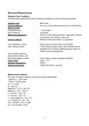
.... Control settings Minolta CA100 photometer, or equivalent User brightness control : User contrast control : User red/white balance, Green/white balance and Blue/white balance control : Power input : Ambient temperature : Analog input mode : Set to Factory preset value (cut off raster) T Set to the monitor under the following conditions, unless otherwise specified...
.... Control settings Minolta CA100 photometer, or equivalent User brightness control : User contrast control : User red/white balance, Green/white balance and Blue/white balance control : Power input : Ambient temperature : Analog input mode : Set to Factory preset value (cut off raster) T Set to the monitor under the following conditions, unless otherwise specified...
AL1751 Service Guide
Page 14
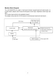
CCFL Drive. Flat Panel and CCFL backlight Inverter board Adapter AC-IN 100V-240V Main Board (Include: Audio board, keyboard) RS232 Connector For white balance adjustment in factory mode HOST Computer Video signal, DDC 14 The adapter will contain a main board (include: keypad board and audio board), an inverter board, adapter which house the flat panel control logic, brightness control logic and DDC. Monitor Block Diagram The LCD MONITOR will provide the 12V DC-power to inverter/power board and main board. The Inverter board will drive the backlight of panel.
CCFL Drive. Flat Panel and CCFL backlight Inverter board Adapter AC-IN 100V-240V Main Board (Include: Audio board, keyboard) RS232 Connector For white balance adjustment in factory mode HOST Computer Video signal, DDC 14 The adapter will contain a main board (include: keypad board and audio board), an inverter board, adapter which house the flat panel control logic, brightness control logic and DDC. Monitor Block Diagram The LCD MONITOR will provide the 12V DC-power to inverter/power board and main board. The Inverter board will drive the backlight of panel.
AL1751 Service Guide
Page 16
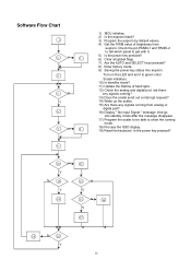
Is the power key pressed? 10 N Y N 12 Y 11 13 N Y 14 15 N 16 Y 17 18 N 19 Y 16 Check the pin PANEL1 and PANEL2 to tell which panel to get ... port? 16) Display " No Input Signal " message. Turn on the LED and set it . 5) Is the power key pressed? 6) Clear all global flags. 7) Are the AUTO and SELECT keys pressed? 8) Enter factory mode. 9) Saving the power key status into standby mode after the message disappear. 17) Program the scalar to be able...
Is the power key pressed? 10 N Y N 12 Y 11 13 N Y 14 15 N 16 Y 17 18 N 19 Y 16 Check the pin PANEL1 and PANEL2 to tell which panel to get ... port? 16) Display " No Input Signal " message. Turn on the LED and set it . 5) Is the power key pressed? 6) Clear all global flags. 7) Are the AUTO and SELECT keys pressed? 8) Enter factory mode. 9) Saving the power key status into standby mode after the message disappear. 17) Program the scalar to be able...
AL1751 Service Guide
Page 18
... W78E65-40P AT24C16AN-10SI-2.7 SI-8050SD AZ1117D-1.8 D-SUB 15PIN DVID CONN. 24P FEMALE PIN HEADER 24P 2.0mm WAFER 4P RIGHT ANGLE PHONE JACK PHONE JACK power jack WAFER 6P RIGHT ANGLE PI TDA7496L BY ST CRYSTAL 14.318MHzHC-49U 20MHZ 18
... W78E65-40P AT24C16AN-10SI-2.7 SI-8050SD AZ1117D-1.8 D-SUB 15PIN DVID CONN. 24P FEMALE PIN HEADER 24P 2.0mm WAFER 4P RIGHT ANGLE PHONE JACK PHONE JACK power jack WAFER 6P RIGHT ANGLE PI TDA7496L BY ST CRYSTAL 14.318MHzHC-49U 20MHZ 18
AL1751 Service Guide
Page 26
...CEE-22 male configuration. One end terminates with units intended for this monitor, following a time-out period, will automatically switch to power outlet of DDC used, communicate additional information about its display capabilities. The communication channel is defined in the center, and disappear ...that continuously transmits EDID information. The DDC1 is a unidirectional data channel from the display to use a cord set by reducing power consumption when there is no video input signal. The appearance is similar to the VESA DDC STANDARD. The display is restored ...
...CEE-22 male configuration. One end terminates with units intended for this monitor, following a time-out period, will automatically switch to power outlet of DDC used, communicate additional information about its display capabilities. The communication channel is defined in the center, and disappear ...that continuously transmits EDID information. The DDC1 is a unidirectional data channel from the display to use a cord set by reducing power consumption when there is no video input signal. The appearance is similar to the VESA DDC STANDARD. The display is restored ...
AL1751 Service Guide
Page 32
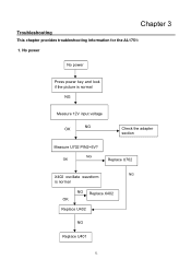
Chapter 3 Troubleshooting This chapter provides troubleshooting information for the AL1751: 1. No power No power Press power key and look if the picture is normal NG Replace X402 OK Replace U402 NG Replace U401 32 NG OK Replace U702 NG X402 oscillate waveform is normal NG Measure 12V input voltage OK NG Check the adapter section Measure U702 PIN2=5V?
Chapter 3 Troubleshooting This chapter provides troubleshooting information for the AL1751: 1. No power No power Press power key and look if the picture is normal NG Replace X402 OK Replace U402 NG Replace U401 32 NG OK Replace U702 NG X402 oscillate waveform is normal NG Measure 12V input voltage OK NG Check the adapter section Measure U702 PIN2=5V?
AL1751 Service Guide
Page 34
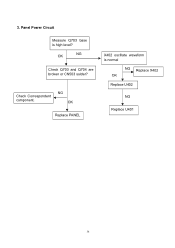
Check Correspondent component. NG OK Replace PANEL X402 oscillate waveform is high level? OK NG Check Q703 and Q704 are broken or CN503 solder? Panel Power Circuit Measure Q703 base is normal NG Replace X402 OK Replace U402 NG Replace U401 34 3.
Check Correspondent component. NG OK Replace PANEL X402 oscillate waveform is high level? OK NG Check Q703 and Q704 are broken or CN503 solder? Panel Power Circuit Measure Q703 base is normal NG Replace X402 OK Replace U402 NG Replace U401 34 3.
AL1751 Service Guide
Page 37
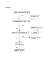
NG OK Reset mute and volume Check power supply of U601is ok? NG Reconnect NG OK Check correspondent component Replace U601 NG Replace speaker 37 6.No Audio Mute and volume setting is 12V? Check connecting is ok? NG OK Check input signal of U601 is ok?
NG OK Reset mute and volume Check power supply of U601is ok? NG Reconnect NG OK Check correspondent component Replace U601 NG Replace speaker 37 6.No Audio Mute and volume setting is 12V? Check connecting is ok? NG OK Check input signal of U601 is ok?
AL1751 Service Guide
Page 38
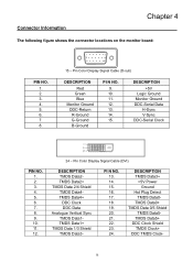
...+ TMDS Data 2/4 Shield TMDS Data4TMDS Data4+ DDC Clock DDC Data Analogue Vertical Sync TMDS Data1TMDS Data1+ TMDS Data 1/3 Shield TMDS Data3- DESCRIPTION TMDS Data3+ +5V Power Ground Hot Plug Detect TMDS Data0- PI N NO. 13. 14. 15. 16. 17. 18. 19. 20. 21. 22. 23. 24. Pin Color Display Signal Cable...
...+ TMDS Data 2/4 Shield TMDS Data4TMDS Data4+ DDC Clock DDC Data Analogue Vertical Sync TMDS Data1TMDS Data1+ TMDS Data 1/3 Shield TMDS Data3- DESCRIPTION TMDS Data3+ +5V Power Ground Hot Plug Detect TMDS Data0- PI N NO. 13. 14. 15. 16. 17. 18. 19. 20. 21. 22. 23. 24. Pin Color Display Signal Cable...
AL1751 Service Guide
Page 44
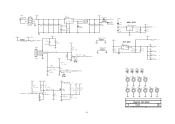
... onBACKLITE AUDIO_SD AUDIO_MU 6.MCU B6 VCC12V_AUDIO VCC12V_AUDIO AUDIO_MU AUDIO_SD 7.AUDIO B4 VOLUME onBACKLITE onPanel_5V/3.3V VCPU VCC12V_AUDIO VCC3.3 VCC1.8 AdjBACKLITE VAA1 VAA2 VAA3 VAA4 VLCD 2.POWER R+ RG+ GB+ BCLK+ CLK- CSZ SCL SDA HWRESET INT AD0 AD1 AD2 AD3 Volume AdjBACKLITE VLCD 4.SCALER SCHEMATIC VCC1.8 VCC3.3 VAA1 VAA2 VAA3 ...VAA4 VCC1.8 VCC3.3 VAA1 VAA2 VAA3 VAA4 PA[0..9] PB[0..9] PA[0..9] PB[0..9] B5 PA[0..9] PB[0..9] VLCD VLCD 5.PANEL INTERFACE Title Size B Date: TSU56AK FOR ACER Document Number TOP Wednesday, January 19, 2005 Sheet 2 Rev D of 8 44
... onBACKLITE AUDIO_SD AUDIO_MU 6.MCU B6 VCC12V_AUDIO VCC12V_AUDIO AUDIO_MU AUDIO_SD 7.AUDIO B4 VOLUME onBACKLITE onPanel_5V/3.3V VCPU VCC12V_AUDIO VCC3.3 VCC1.8 AdjBACKLITE VAA1 VAA2 VAA3 VAA4 VLCD 2.POWER R+ RG+ GB+ BCLK+ CLK- CSZ SCL SDA HWRESET INT AD0 AD1 AD2 AD3 Volume AdjBACKLITE VLCD 4.SCALER SCHEMATIC VCC1.8 VCC3.3 VAA1 VAA2 VAA3 ...VAA4 VCC1.8 VCC3.3 VAA1 VAA2 VAA3 VAA4 PA[0..9] PB[0..9] PA[0..9] PB[0..9] B5 PA[0..9] PB[0..9] VLCD VLCD 5.PANEL INTERFACE Title Size B Date: TSU56AK FOR ACER Document Number TOP Wednesday, January 19, 2005 Sheet 2 Rev D of 8 44
AL1751 Service Guide
Page 45
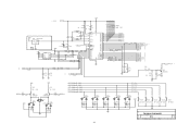
2 5 /ON 3 GND CN701 LP701 POWER JACK 1+12V_IN 6 3 5 2 4 1 INDUTOR-P VCC12V U701 SI-8050SD 1 VIN FBK 4 2 Vout + + C701 C702 C703 C706 C707 0.001uF 220uF/16V 220uF/16V 0.1uF/16V 0.1uF/16V C710 0.... Screw Hole 1 1 1 1 MH5 MH6 MH7 MH8 MH9 MH10 Screw Hole Screw Hole Screw Hole Screw Hole Screw Hole Screw Hole 1 1 1 1 1 1 Title Size B Date: TSU56AK FOR ACER Document Number POWER Wednesday, January 19, 2005 Sheet 3 Rev D of 8 45
2 5 /ON 3 GND CN701 LP701 POWER JACK 1+12V_IN 6 3 5 2 4 1 INDUTOR-P VCC12V U701 SI-8050SD 1 VIN FBK 4 2 Vout + + C701 C702 C703 C706 C707 0.001uF 220uF/16V 220uF/16V 0.1uF/16V 0.1uF/16V C710 0.... Screw Hole 1 1 1 1 MH5 MH6 MH7 MH8 MH9 MH10 Screw Hole Screw Hole Screw Hole Screw Hole Screw Hole Screw Hole 1 1 1 1 1 1 Title Size B Date: TSU56AK FOR ACER Document Number POWER Wednesday, January 19, 2005 Sheet 3 Rev D of 8 45
AL1751 Service Guide
Page 49
... DP1 DUAL LED 3 D403 BAV99 1 3 2 1 2 1 C451 1000pF 2 C452 1000pF ENTER R430 470` 1/16W RIGHT R431 470` 1/16W AUTO R432 470` 1/16W LEFT R435 470` 1/16W POWER R436 470` 1/16W D404 BAV99 C443 0.001uF D405 BAV99 C442 0.001uF 49 2 3 1 2 3 1 2 3 1 2 3 1 2 3 1 D406 BAV99 C441 0.001uF D407 BAV99 C440 0.001uF KEY_MENU KEY_RIGHT KEY_AUTO KEY_LEFT ...KEY_ONOFF D408 BAV99 C439 VCPU SW401 LCD ONOFF SW402 KEY LEFT 0.001uF SW403 SW404 KEY AUTO KEY RIGHT SW405 KEY MENU Title TSU56AK FOR ACER Size Document Number B MPU Date: Wednesday, January 19, 2005 Sheet 7 Rev D of 8
... DP1 DUAL LED 3 D403 BAV99 1 3 2 1 2 1 C451 1000pF 2 C452 1000pF ENTER R430 470` 1/16W RIGHT R431 470` 1/16W AUTO R432 470` 1/16W LEFT R435 470` 1/16W POWER R436 470` 1/16W D404 BAV99 C443 0.001uF D405 BAV99 C442 0.001uF 49 2 3 1 2 3 1 2 3 1 2 3 1 2 3 1 D406 BAV99 C441 0.001uF D407 BAV99 C440 0.001uF KEY_MENU KEY_RIGHT KEY_AUTO KEY_LEFT ...KEY_ONOFF D408 BAV99 C439 VCPU SW401 LCD ONOFF SW402 KEY LEFT 0.001uF SW403 SW404 KEY AUTO KEY RIGHT SW405 KEY MENU Title TSU56AK FOR ACER Size Document Number B MPU Date: Wednesday, January 19, 2005 Sheet 7 Rev D of 8


