AL1731 Service Guide
Page 2
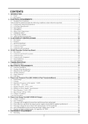
... Surge Test (IEC 61000-4-5 Surge 43 8.1 Climatic Condition ...43 8.2 Test Conditions:...43 8.3 The surge will be performed under the following conditions, unless otherwise specified 4 2.2 LCD monitor General specification ...4 2.3 LCD Panel Specification ...5 2.4 Input Signals...11 2.5 CONTROLS ...15 2.6 White Color Temperature...19 2.7 POWER SUPPLY ...20 2.8 Plug & Play (EDID) ...22 2.9 Audio Technical specification ...23 3. INTRODUCTION ...3 1.1 Scope...
... Surge Test (IEC 61000-4-5 Surge 43 8.1 Climatic Condition ...43 8.2 Test Conditions:...43 8.3 The surge will be performed under the following conditions, unless otherwise specified 4 2.2 LCD monitor General specification ...4 2.3 LCD Panel Specification ...5 2.4 Input Signals...11 2.5 CONTROLS ...15 2.6 White Color Temperature...19 2.7 POWER SUPPLY ...20 2.8 Plug & Play (EDID) ...22 2.9 Audio Technical specification ...23 3. INTRODUCTION ...3 1.1 Scope...
AL1731 Service Guide
Page 4
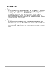
... This specification defines the requirements for the 17" MICRO-PROCESSOR based Multimode supported high resolution color LCD monitor, Monitor can support multi-media function as Composite signal and S-Video signal input. 1.2 Description The LCD monitor is designed with the latest LCD technology to general 15 pin D-sub VGA connector and DVI-D digital connector, eliminates the requirement...
... This specification defines the requirements for the 17" MICRO-PROCESSOR based Multimode supported high resolution color LCD monitor, Monitor can support multi-media function as Composite signal and S-Video signal input. 1.2 Description The LCD monitor is designed with the latest LCD technology to general 15 pin D-sub VGA connector and DVI-D digital connector, eliminates the requirement...
AL1731 Service Guide
Page 5
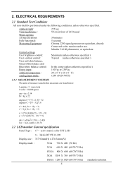
... - 12v' + 9] y = (3v')/[(9u'/2) - 12v' + 9] nits = cd/(m2) = Ft-L x 3.426 lux = foot-candle x 10.76 2.2 LCD monitor General specification Panel Type : 17 " active matrix color TFT LCD 1). Minolta CA100 photometer, or equivalent Maximum (unless otherwise specified ) Typical (unless otherwise specified ) In the center (unless otherwise specified ) 110Vac or... = 1 nano tesla 1 tesla = 10,000 gauss cm = in front of LCD panel 30 minutes 5 seconds Chroma 2250 signal generator or equivalent, directly Connected to the monitor under the following conditions, unless otherwise specified. 2.
... - 12v' + 9] y = (3v')/[(9u'/2) - 12v' + 9] nits = cd/(m2) = Ft-L x 3.426 lux = foot-candle x 10.76 2.2 LCD monitor General specification Panel Type : 17 " active matrix color TFT LCD 1). Minolta CA100 photometer, or equivalent Maximum (unless otherwise specified ) Typical (unless otherwise specified ) In the center (unless otherwise specified ) 110Vac or... = 1 nano tesla 1 tesla = 10,000 gauss cm = in front of LCD panel 30 minutes 5 seconds Chroma 2250 signal generator or equivalent, directly Connected to the monitor under the following conditions, unless otherwise specified. 2.
AL1731 Service Guide
Page 12
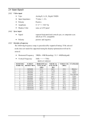
... • Amplitude • Display Color Analog R, G, B., Digital TMDS 75 ohm +/- 2% Positive 0 - 0.7 +/- 0.05 Vp same as LCD panel 2.4.2 Sync input • Signal • Polarity separate horizontal and vertical sync, or composite sync which are TTL compatible positive and negative. 2.4.3 Interface... will not be assured. • Horizontal Frequency 30KHz --80KHz(analog), 31.5- 64KHz(digital) • Vertical Frequency 56Hz ---------75Hz DISPLAY MODES MONITOR MODE NO. 1 2 3 4 5 6 7 8 9 10 11 12 SCREEN RESOLUTION 640X480 640X480 640X480 720X400 800X600 800X600 800X600 1024X768 1024X768...
... • Amplitude • Display Color Analog R, G, B., Digital TMDS 75 ohm +/- 2% Positive 0 - 0.7 +/- 0.05 Vp same as LCD panel 2.4.2 Sync input • Signal • Polarity separate horizontal and vertical sync, or composite sync which are TTL compatible positive and negative. 2.4.3 Interface... will not be assured. • Horizontal Frequency 30KHz --80KHz(analog), 31.5- 64KHz(digital) • Vertical Frequency 56Hz ---------75Hz DISPLAY MODES MONITOR MODE NO. 1 2 3 4 5 6 7 8 9 10 11 12 SCREEN RESOLUTION 640X480 640X480 640X480 720X400 800X600 800X600 800X600 1024X768 1024X768...
AL1731 Service Guide
Page 16
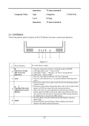
... is in "Power Saving Mode". 4. Direct press either left side) function selection. 1. Press the Menu will Auto-Adjusting. 2. Monitor is off --- When selection you want adjusting function then press Menu buttons again for OSD first menu (left or right control button ... Type Level Impedance 75 ohm terminated Composite 0.7Vpp 75 ohm terminated : NTSC/PAL 2.5 CONTROLS A brief description and the location of all LCD Monitor functions controls and indicators: 1 Stereo Speakers 2 Soft Power Switch (DC Power-On Indicator) 3 Auto 4 Function Select and Adjustment Control Buttons...
... is in "Power Saving Mode". 4. Direct press either left side) function selection. 1. Press the Menu will Auto-Adjusting. 2. Monitor is off --- When selection you want adjusting function then press Menu buttons again for OSD first menu (left or right control button ... Type Level Impedance 75 ohm terminated Composite 0.7Vpp 75 ohm terminated : NTSC/PAL 2.5 CONTROLS A brief description and the location of all LCD Monitor functions controls and indicators: 1 Stereo Speakers 2 Soft Power Switch (DC Power-On Indicator) 3 Auto 4 Function Select and Adjustment Control Buttons...
AL1731 Service Guide
Page 25
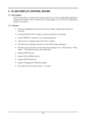
...control board is design to directly convert the analog RGB signals from standard VGA display card to optimum LCD timing signals so as to construct a high display quality LCD monitor. 3.2 Features • On board embedded micro-processor to detect display timings and control user functions.... • Using PixelWorks PW131 design to generate optimum LCD timings. 2 • Using E PROM to memorize every adjusted parameter. &#...
...control board is design to directly convert the analog RGB signals from standard VGA display card to optimum LCD timing signals so as to construct a high display quality LCD monitor. 3.2 Features • On board embedded micro-processor to detect display timings and control user functions.... • Using PixelWorks PW131 design to generate optimum LCD timings. 2 • Using E PROM to memorize every adjusted parameter. &#...
AL1731 User Guide
Page 1
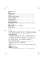
... Interface for a Class B digital device, pursuant to provide reasonable protection against harmful interference in setting up and using the LCD Monitor. You are reserved. If this manual may cause harmful interference to this equipment. Cet appareil numérique de la...assist users in a residential installation. Table of Contents Preface ...1 Chapter 1 Installation...2 Unpacking ...2 Connecting the LCD Monitor and Base 2 Viewing Angle Adjustment...2 Detaching LCD Monitor from that to radio or television reception, which the receiver is subject to operate the equipment. No ...
... Interface for a Class B digital device, pursuant to provide reasonable protection against harmful interference in setting up and using the LCD Monitor. You are reserved. If this manual may cause harmful interference to this equipment. Cet appareil numérique de la...assist users in a residential installation. Table of Contents Preface ...1 Chapter 1 Installation...2 Unpacking ...2 Connecting the LCD Monitor and Base 2 Viewing Angle Adjustment...2 Detaching LCD Monitor from that to radio or television reception, which the receiver is subject to operate the equipment. No ...

AL1731 User Guide
Page 2
... is frayed or damaged. * Liquid spilled into LCD Monitor or the monitor has been exposed to rain. * LCD Monitor or the case is required to connect this range could result in the box: * LCD Monitor * User's Manual * 1.8M Monitor-to-PC VGA Cable * AC Adapter * 1.8M Monitor-to a power outlet. Storing the LCD Monitor outside this device to -PC DVI-D Cable...
... is frayed or damaged. * Liquid spilled into LCD Monitor or the monitor has been exposed to rain. * LCD Monitor or the case is required to connect this range could result in the box: * LCD Monitor * User's Manual * 1.8M Monitor-to-PC VGA Cable * AC Adapter * 1.8M Monitor-to a power outlet. Storing the LCD Monitor outside this device to -PC DVI-D Cable...

AL1731 User Guide
Page 3
...AV and S-Video cable 1. Connect one end of the signal cable to the AC adapter.(See Fig. 1-6) 2. Connect the power cord to the LCD Monitor's VGA port or DVI port.(See Fig 1-5) 3. Connect the AV cable to RCA Jack and follow the color and the other side connect to ...connector to AV source. Connecting the Audio Cable 1. Connect the other end of the monitor. 3. Detaching LCD Monitor from Its Stand Unscrew screws n the swivel base support column and pull it from reaching the LCD Monitor. Figure 1-3 Interface for adding protection against power surges to prevent the errects of the ...
...AV and S-Video cable 1. Connect one end of the signal cable to the AC adapter.(See Fig. 1-6) 2. Connect the power cord to the LCD Monitor's VGA port or DVI port.(See Fig 1-5) 3. Connect the AV cable to RCA Jack and follow the color and the other side connect to ...connector to AV source. Connecting the Audio Cable 1. Connect the other end of the monitor. 3. Detaching LCD Monitor from Its Stand Unscrew screws n the swivel base support column and pull it from reaching the LCD Monitor. Figure 1-3 Interface for adding protection against power surges to prevent the errects of the ...


