

AL1717 Service Guide
Page 4
... not occur in a residential installation. WARNING: To prevent fire or chock hazard, do not expose the monitor to operate the equipment. Increase the separation between the equipment and receiver. 3. These limits are present inside the monitor. As an ENERGY STAR® Partner our company has determined that to provide reasonable protection against...
... not occur in a residential installation. WARNING: To prevent fire or chock hazard, do not expose the monitor to operate the equipment. Increase the separation between the equipment and receiver. 3. These limits are present inside the monitor. As an ENERGY STAR® Partner our company has determined that to provide reasonable protection against...

AL1717 Service Guide
Page 5
... covers can result in a wet basement. PRECAUTIONS z Do not use an adapter to ground the appliance safely. z Do not place the monitor on the monitor. z Unplug the unit during a lightning storm or when it can injure a person and cause serious damage to power surges. Never spill liquids...power strips and extension cords. Use only a trolley or stand recommended by the manufacture and follow the kit instructions. Do not place the monitor on the monitor cabinet. near the equipment and shall be installed near a bathtub, washbowl, kitchen sink, laundry tub, Swimming pool or in fire or...
... covers can result in a wet basement. PRECAUTIONS z Do not use an adapter to ground the appliance safely. z Do not place the monitor on the monitor. z Unplug the unit during a lightning storm or when it can injure a person and cause serious damage to power surges. Never spill liquids...power strips and extension cords. Use only a trolley or stand recommended by the manufacture and follow the kit instructions. Do not place the monitor on the monitor cabinet. near the equipment and shall be installed near a bathtub, washbowl, kitchen sink, laundry tub, Swimming pool or in fire or...

AL1717 Service Guide
Page 6
... following symptoms are normal with LCD monitor and do not indicate a problem. Turn off the Power Switch for hours. z You may find slightly uneven brightness in the screen depending on again to ...
... following symptoms are normal with LCD monitor and do not indicate a problem. Turn off the Power Switch for hours. z You may find slightly uneven brightness in the screen depending on again to ...

AL1717 Service Guide
Page 7
Table of contents Chapter 1 Monitor Feature 8 Chapter 2 Operating Instruction 27 Chapter 3 Machine Disassembly and Replacement 35 Chapter 4 Troubleshooting 48 Chapter 5 Connector Information 52 Chapter 6 FRU List 53 Chapter 7 Schematic Diagram 63 - 7 -
Table of contents Chapter 1 Monitor Feature 8 Chapter 2 Operating Instruction 27 Chapter 3 Machine Disassembly and Replacement 35 Chapter 4 Troubleshooting 48 Chapter 5 Connector Information 52 Chapter 6 FRU List 53 Chapter 7 Schematic Diagram 63 - 7 -
AL1717 Service Guide
Page 8
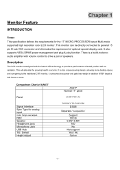
...Interface Sync Type for the 17" MICRO-PROCESSOR based Multi-mode supported high resolution color LCD monitor. This monitor can be directly connected to the traditional CRT monitor, it consumes less power and gets less weight in stereo audio amplifier with no radiation. ...allowing more . It also supports VESA DPMS power management and plug & play function. This will alleviate the growing health concerns. Monitor Feature INTRODUCTION Chapter 1 Scope This specification defines the requirements for analog input Color Temp user adjust DDC Speaker Headphone Jack Microphone Jack ...
...Interface Sync Type for the 17" MICRO-PROCESSOR based Multi-mode supported high resolution color LCD monitor. This monitor can be directly connected to the traditional CRT monitor, it consumes less power and gets less weight in stereo audio amplifier with no radiation. ...allowing more . It also supports VESA DPMS power management and plug & play function. This will alleviate the growing health concerns. Monitor Feature INTRODUCTION Chapter 1 Scope This specification defines the requirements for analog input Color Temp user adjust DDC Speaker Headphone Jack Microphone Jack ...
AL1717 Service Guide
Page 9
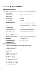
... of LCD panel Warrn up time All specifications : 30 minutes Fully functional : 5 seconds Measuring Equipment : Chroma 2250 signal generator or equivalent, directly Connected to the monitor under the following conditions, unless otherwise specified. ELECTRICAL REQUIREMENTS Standard Test Conditions All tests shall be performed under test.
... of LCD panel Warrn up time All specifications : 30 minutes Fully functional : 5 seconds Measuring Equipment : Chroma 2250 signal generator or equivalent, directly Connected to the monitor under the following conditions, unless otherwise specified. ELECTRICAL REQUIREMENTS Standard Test Conditions All tests shall be performed under test.
AL1717 Service Guide
Page 10
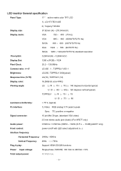
...: Support VESA DDC2B functions Power Input voltage: Single phase, 50/60HZ, 100 VAC to 240VAC ±10% Total output power: 40 Watt max. - 10 - LCD monitor General specification Panel Type: 17 " active matrix color TFT LCD 1).
...: Support VESA DDC2B functions Power Input voltage: Single phase, 50/60HZ, 100 VAC to 240VAC ±10% Total output power: 40 Watt max. - 10 - LCD monitor General specification Panel Type: 17 " active matrix color TFT LCD 1).
AL1717 Service Guide
Page 19
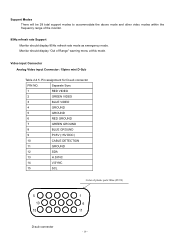
Video input Connector Analog Video input Connector: 15pins mini D-Sub Table 2.4.5. Monitor should display 85Hz refresh rate mode as emergency mode. Pin assignment for D-sub connector PIN NO. Separate Sync 1 RED VIDEO 2 GREEN VIDEO 3 BLUE VIDEO 4 GROUND 5 ... mode. Support Modes There will be 28 total support modes to accommodate the above mode and other video modes within the frequency range of the monitor. 85Hz refresh rate Support Monitor should display "Out of plastic parts: Blue (PC99) 5 1 10 6 15 11 D-sub connector - 19 -
Video input Connector Analog Video input Connector: 15pins mini D-Sub Table 2.4.5. Monitor should display 85Hz refresh rate mode as emergency mode. Pin assignment for D-sub connector PIN NO. Separate Sync 1 RED VIDEO 2 GREEN VIDEO 3 BLUE VIDEO 4 GROUND 5 ... mode. Support Modes There will be 28 total support modes to accommodate the above mode and other video modes within the frequency range of the monitor. 85Hz refresh rate Support Monitor should display "Out of plastic parts: Blue (PC99) 5 1 10 6 15 11 D-sub connector - 19 -
AL1717 Service Guide
Page 20
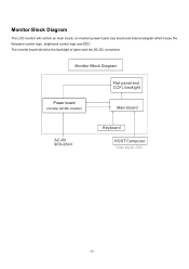
The inverter board will contain an main board, an inverter/ power board, key board and internal adapter which house the flat panel control logic, brightness control logic and DDC. Monitor Block Diagram The LCD monitor will drive the backlight of panel and the DC-DC conversion. Power board (include: AC/DC,inverter) - 20 -
The inverter board will contain an main board, an inverter/ power board, key board and internal adapter which house the flat panel control logic, brightness control logic and DDC. Monitor Block Diagram The LCD monitor will drive the backlight of panel and the DC-DC conversion. Power board (include: AC/DC,inverter) - 20 -
AL1717 Service Guide
Page 25
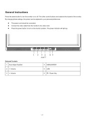
z The power cord should be adjusted to turn the monitor on the monitor position. z Connect the video cable from the monitor to turn on or off. General Instructions Press the power button to the video card. The other control buttons are located at front panel of the monitor. z Press the power button to your personal preferences. External Controls 1 Auto Adjust Key/Exit 2 / Volume AA677 4 MENU/ENTER 5 LED 6 / Power Key - 25 - By changing these settings, the picture can be connected. The power indicator will light up.
z The power cord should be adjusted to turn the monitor on the monitor position. z Connect the video cable from the monitor to turn on or off. General Instructions Press the power button to the video card. The other control buttons are located at front panel of the monitor. z Press the power button to your personal preferences. External Controls 1 Auto Adjust Key/Exit 2 / Volume AA677 4 MENU/ENTER 5 LED 6 / Power Key - 25 - By changing these settings, the picture can be connected. The power indicator will light up.
AL1717 Service Guide
Page 26
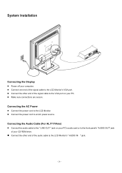
z Connect the other end of the audio cable to the LCD Monitor's " AUDIO IN " jack. - 26 - Connecting the AC Power z Connect the power cord to an AC power source. System Installation Connecting the Display z Power off your ... sure connections are secure. z Connect one end of your computer. z Connect the other end of the signal cable to the LCD Monitor's VGA port. z Connect the power cord to the LCD Monitor. Connecting the Audio Cable (For AL1717Ams) z Connect the audio cable to the " LINE OUT " jack on your PC's audio card...
z Connect the other end of the audio cable to the LCD Monitor's " AUDIO IN " jack. - 26 - Connecting the AC Power z Connect the power cord to an AC power source. System Installation Connecting the Display z Power off your ... sure connections are secure. z Connect one end of your computer. z Connect the other end of the signal cable to the LCD Monitor's VGA port. z Connect the power cord to the LCD Monitor. Connecting the Audio Cable (For AL1717Ams) z Connect the audio cable to the " LINE OUT " jack on your PC's audio card...
AL1717 Service Guide
Page 27
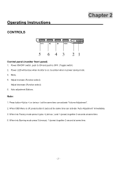
be blue when monitor is off, press button 5 (auto) at same time. 5. When OSD Menu is on; Menu. 4. Power ON/OFF switch, push to ON and push to OFF. (... mode press 5 (menus), 1 (power) together 2 second at the same time can activate "Auto Adjustment" immediately. 3. Adjust decrease (Function select). 5. Operating Instructions CONTROLS Chapter 2 Control panel (monitor front panel) 1.
be blue when monitor is off, press button 5 (auto) at same time. 5. When OSD Menu is on; Menu. 4. Power ON/OFF switch, push to ON and push to OFF. (... mode press 5 (menus), 1 (power) together 2 second at the same time can activate "Auto Adjustment" immediately. 3. Adjust decrease (Function select). 5. Operating Instructions CONTROLS Chapter 2 Control panel (monitor front panel) 1.
AL1717 Service Guide
Page 30
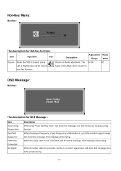
... Adjustment Reset Range Value Volume When the OSD is no active signal input, will be flying. This message will show this message, and the monitor do the auto config function. Hot-Key Menu: Outline: The description for OSD Message : Item Auto Config Please Wait Input Not Supported Cable ... will show this message, then enter power saving. - 30 - When the video cable is connected, but the is closed, press Volume of the monitor support range, will be Volume Audio will show this message. The 0-100 50 Left or Right button will be Mute when volume=0. When the Hsync...
... Adjustment Reset Range Value Volume When the OSD is no active signal input, will be flying. This message will show this message, and the monitor do the auto config function. Hot-Key Menu: Outline: The description for OSD Message : Item Auto Config Please Wait Input Not Supported Cable ... will show this message, then enter power saving. - 30 - When the video cable is connected, but the is closed, press Volume of the monitor support range, will be Volume Audio will show this message. The 0-100 50 Left or Right button will be Mute when volume=0. When the Hsync...
AL1717 Service Guide
Page 31
... and Contrast value to Max. 2) Auto Balance Adjust each R, G, B contrast (gain) and offset. Item of R, G, B gain shall be located in the center. LOGO: When the monitor is depends on , the LOGO will be showed in 3.
... and Contrast value to Max. 2) Auto Balance Adjust each R, G, B contrast (gain) and offset. Item of R, G, B gain shall be located in the center. LOGO: When the monitor is depends on , the LOGO will be showed in 3.

AL1717 Service Guide
Page 32
...Standards Association(VESA) and/or the United States Environmental Protection Agency (EPA) and The Swedish Confederation Employees (NUTEK). It allows the monitor to inform the host system of its display capabilities. The voltage rating for the power cord shall be 125 volt AC. The appearance...5-15 style and is defined in European counties. - 32 - The communication channel is UL listed and CSA labeled. This reduces the monitor's internal power supply consumption. Using The Right Power Cord The accessory power cord for the Northern American region is equipped with VESA DDC2B ...
...Standards Association(VESA) and/or the United States Environmental Protection Agency (EPA) and The Swedish Confederation Employees (NUTEK). It allows the monitor to inform the host system of its display capabilities. The voltage rating for the power cord shall be 125 volt AC. The appearance...5-15 style and is defined in European counties. - 32 - The communication channel is UL listed and CSA labeled. This reduces the monitor's internal power supply consumption. Using The Right Power Cord The accessory power cord for the Northern American region is equipped with VESA DDC2B ...
AL1717 Service Guide
Page 33
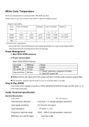
... stand-by ; Dark (DC power off) ‹Measured from AC input end of the VGA connector). suspend; Meet VESA DPMS proposal 2. Plug & Play (EDID) The monitor will be user which is 4 preset as 9300, 7500,6500 and User, Default value of color setting Color Color Coordinate Tolerance Color Coordinate Tolerance Temp...
... stand-by ; Dark (DC power off) ‹Measured from AC input end of the VGA connector). suspend; Meet VESA DPMS proposal 2. Plug & Play (EDID) The monitor will be user which is 4 preset as 9300, 7500,6500 and User, Default value of color setting Color Color Coordinate Tolerance Color Coordinate Tolerance Temp...

AL1717 Service Guide
Page 35
... front of the user (i.e., front-to back, side-to-side, and top-to 10Hz, along each of the three axes. This requires one hour for monitor product Product Weight height Specs Package Drop Specification Listed below are standards of drop heights for each of the system after testing.
... front of the user (i.e., front-to back, side-to-side, and top-to 10Hz, along each of the three axes. This requires one hour for monitor product Product Weight height Specs Package Drop Specification Listed below are standards of drop heights for each of the system after testing.

AL1717 Service Guide
Page 41
Gap between -5º~ +15º and it should not have any noise. - 41 - When adjust the monitor angle, the range should be limited between panel with bezel is 0 mm < gap < 1.2 mm Swivel Title noise spec. GAP Spec.
Gap between -5º~ +15º and it should not have any noise. - 41 - When adjust the monitor angle, the range should be limited between panel with bezel is 0 mm < gap < 1.2 mm Swivel Title noise spec. GAP Spec.
AL1717 Service Guide
Page 43
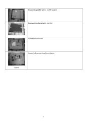
To reverse the monitor. Connect speaker wires on VK board. Assemble the power board onto chassis. AA677 43 Connect the bezel with monitor.
To reverse the monitor. Connect speaker wires on VK board. Assemble the power board onto chassis. AA677 43 Connect the bezel with monitor.
AL1717 Service Guide
Page 46
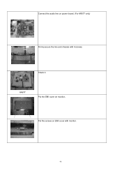
Put the screws on power board. (For AR577 only) Firmly secure the line and chassis with monitor. 46 Connect the audio line on EMI cover with 4 screws. AA677 Put the EMI cover on monitor.. Check it.
Put the screws on power board. (For AR577 only) Firmly secure the line and chassis with monitor. 46 Connect the audio line on EMI cover with 4 screws. AA677 Put the EMI cover on monitor.. Check it.


