

AC 501 User Guide
Page 3
...the manufacturer while setting up the device, first place it over it from the main power supply to protect the device against moisture. 6. Make sure no user serviceable parts inside. Power cable or power plug are no sharp objects or liquids enter the device via its air circulation openings... a clean dampened cloth in a fire or an electric shock. 14. This could result in stead. 4. The device shows obvious signs of the main power supply. 9. To avoid damaging the device, only use . 3. If the device will not be used for any objects on the device. 12. Please read...
...the manufacturer while setting up the device, first place it over it from the main power supply to protect the device against moisture. 6. Make sure no user serviceable parts inside. Power cable or power plug are no sharp objects or liquids enter the device via its air circulation openings... a clean dampened cloth in a fire or an electric shock. 14. This could result in stead. 4. The device shows obvious signs of the main power supply. 9. To avoid damaging the device, only use . 3. If the device will not be used for any objects on the device. 12. Please read...
AC 501 User Guide
Page 4
However, there is no guarantee that only the supplied power cord be determined by turning the equipment off and on a circuit different from that to correct the interference by the manufacturers may cause harmful interference ... operate this equipment. It is encouraged to try to which can radiate radio frequency energy, and, if not installed and used . Connect the equipment with a power socket on , the user is essential that interference will not occur in accordance with the limits for help.
However, there is no guarantee that only the supplied power cord be determined by turning the equipment off and on a circuit different from that to correct the interference by the manufacturers may cause harmful interference ... operate this equipment. It is encouraged to try to which can radiate radio frequency energy, and, if not installed and used . Connect the equipment with a power socket on , the user is essential that interference will not occur in accordance with the limits for help.
AC 501 User Guide
Page 11
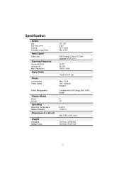
Scanning Frequency Horizontal (KHz) Vertical (Hz) Max. Specification Screen Size Dot Pitch (mm) Surface Viewable Image Area Input Signal Video Sync. Resolution Signal Cable Power Consumption Power Supply Power Management Display Modes Preset By User Operating Operating Temperature Relative Humidity Dimensions (L x W x H) Weight Unpacked Packed in box 15" CRT 0.28 Non -glare 260 x 195 RGB ...
Scanning Frequency Horizontal (KHz) Vertical (Hz) Max. Specification Screen Size Dot Pitch (mm) Surface Viewable Image Area Input Signal Video Sync. Resolution Signal Cable Power Consumption Power Supply Power Management Display Modes Preset By User Operating Operating Temperature Relative Humidity Dimensions (L x W x H) Weight Unpacked Packed in box 15" CRT 0.28 Non -glare 260 x 195 RGB ...

AC501 Monitor Service Guide
Page 12
...makes screen rast er. Circuit. !"-11.7V: For vertical deflection negative power. D. Deflection Produce YOKE deflect ion current of CRT to the cathode of horizontal and vertical, CRT H.V and bi as that supply all the picture performance. Video Amplify the video signal and add the ...signal to produce video on the screen. B. 2. C. Digital Controllable With the EEPROM and PROGRAM, the micro-processor(u-P) control all the circuit power. OPERATION THEOREM A. From the key ...
...makes screen rast er. Circuit. !"-11.7V: For vertical deflection negative power. D. Deflection Produce YOKE deflect ion current of CRT to the cathode of horizontal and vertical, CRT H.V and bi as that supply all the picture performance. Video Amplify the video signal and add the ...signal to produce video on the screen. B. 2. C. Digital Controllable With the EEPROM and PROGRAM, the micro-processor(u-P) control all the circuit power. OPERATION THEOREM A. From the key ...
AC501 Monitor Service Guide
Page 14
Power Supply F-1. D904, and smoothed by C906 to provide DC operating voltage for a time via Q970 and R971, that...from its peak value. When the monitor wakes up from the OFF mode to the ON mode , the +13Vs will provide power to the normal reset voltage across T900 when Q901 turn off +13Vs and +7.5Vs outputs. Snubber Ckt Energy stored in the ...Q902 to complete start-up of 16V, U901 is initially applied to an internal 2.5V reference. Flyback And Pwm Ckt When power is enabled, turning on Q901 and turning off snubber made up action. Primary current is sensed by R914, R916, R917 and...
Power Supply F-1. D904, and smoothed by C906 to provide DC operating voltage for a time via Q970 and R971, that...from its peak value. When the monitor wakes up from the OFF mode to the ON mode , the +13Vs will provide power to the normal reset voltage across T900 when Q901 turn off +13Vs and +7.5Vs outputs. Snubber Ckt Energy stored in the ...Q902 to complete start-up of 16V, U901 is initially applied to an internal 2.5V reference. Flyback And Pwm Ckt When power is enabled, turning on Q901 and turning off snubber made up action. Primary current is sensed by R914, R916, R917 and...

AC501 Monitor Service Guide
Page 23
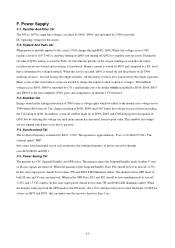
Check and repaor Q902, Q903, U901, D908, R931 D909, R908 Is 13V in spec? OK S to p Check and repair R919, R912, R918, C912 23 Is 60V voltage correct? Is 7.5V in spec? TROUBLE SHOOTING A. 4. No Check VR901, D941, A942, Q943 No Check D940, Q940, R945, D951 No Check D942, C946 Combine with No monitor check operating frequency? Power Supply Check S ta rt Check Yes fuse open Check and repaor EMI Filter and Q901, I/P Rectifer R909, U901, R907 Is Q901 VDS No waveform normally?
Check and repaor Q902, Q903, U901, D908, R931 D909, R908 Is 13V in spec? OK S to p Check and repair R919, R912, R918, C912 23 Is 60V voltage correct? Is 7.5V in spec? TROUBLE SHOOTING A. 4. No Check VR901, D941, A942, Q943 No Check D940, Q940, R945, D951 No Check D942, C946 Combine with No monitor check operating frequency? Power Supply Check S ta rt Check Yes fuse open Check and repaor EMI Filter and Q901, I/P Rectifer R909, U901, R907 Is Q901 VDS No waveform normally?

AC501 Monitor Service Guide
Page 24
T 24 T pin 3, voltage about 1200 Vpp Ye s C he ck F. B . B . B . Monitor Check Flow Chart B-1 No Raster No raster Check power No indecator lighted Ye s Check contrast & brightness control adjust to MAX. Ye s Check HEATER voltage= +6.3VDC G1 = 50-80 VDC G2 = 500-600 VDC Ye s Check CRT Check AC Ye s power input No Check Q801 collector voltage about 80-155V Ye s C he ck F. B. T Check power supply circuit Check power supply c ir c u it Check U401 No No Check U401 pin7 output sequare wave from Ye s Check Q506 Ye s No C he ck F.
T 24 T pin 3, voltage about 1200 Vpp Ye s C he ck F. B . B . B . Monitor Check Flow Chart B-1 No Raster No raster Check power No indecator lighted Ye s Check contrast & brightness control adjust to MAX. Ye s Check HEATER voltage= +6.3VDC G1 = 50-80 VDC G2 = 500-600 VDC Ye s Check CRT Check AC Ye s power input No Check Q801 collector voltage about 80-155V Ye s C he ck F. B. T Check power supply circuit Check power supply c ir c u it Check U401 No No Check U401 pin7 output sequare wave from Ye s Check Q506 Ye s No C he ck F.

AC501 Monitor Service Guide
Page 26
No Check No R601, R605 Check power supply circuit No Check U401 26 No Vertical Defl ection ( Rester Become A Horizontal Line) No vertical deflenction Yes Check U601 Pin 2 about 15V/40V PIN 4 about -12VD C Yes Check U401 Pin 12, 13 output saw-tooth w a v e fo rm Yes Check U601,D601 Yes C heck D .Y. B-3.
No Check No R601, R605 Check power supply circuit No Check U401 26 No Vertical Defl ection ( Rester Become A Horizontal Line) No vertical deflenction Yes Check U601 Pin 2 about 15V/40V PIN 4 about -12VD C Yes Check U401 Pin 12, 13 output saw-tooth w a v e fo rm Yes Check U601,D601 Yes C heck D .Y. B-3.


