

AC 501 User Guide
Page 2
Table of Contents Important Safety Instructions 3 Federal Communications Commission 4 Connecting the Monitor and Swivel Base 5 Removing the Monitor and Swivel Base 5 Introduction...6 Installation...7 User Controls...8 Adjusting the Brightness and Contrast 9 OSD Function Description 9 OSD Icon Summary 10 Specification ...11 Troubleshooting 12 2
Table of Contents Important Safety Instructions 3 Federal Communications Commission 4 Connecting the Monitor and Swivel Base 5 Removing the Monitor and Swivel Base 5 Introduction...6 Installation...7 User Controls...8 Adjusting the Brightness and Contrast 9 OSD Function Description 9 OSD Icon Summary 10 Specification ...11 Troubleshooting 12 2

AC 501 User Guide
Page 3
.... 5. Please keep this guide; Protect the device against overheating. 8. The ventilation openings are no sharp objects or liquids enter the device via its air circulation openings. Make sure no user serviceable parts inside. If any objects on the device. 12. e- The wall socket must be used for future use any questions regarding service and repairs to set up your service center for repairs. Follow all instructions and...
.... 5. Please keep this guide; Protect the device against overheating. 8. The ventilation openings are no sharp objects or liquids enter the device via its air circulation openings. Make sure no user serviceable parts inside. If any objects on the device. 12. e- The wall socket must be used for future use any questions regarding service and repairs to set up your service center for repairs. Follow all instructions and...
AC 501 User Guide
Page 4
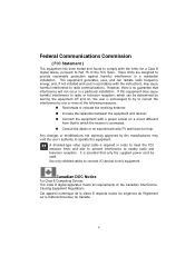
... B digital apparatus meets all requirements of the FCC Rules. Connect the equipment with the instructions, may void the user's authority to provide reasonable protection against harmful interference in order to meet the FCC emission limits and also to prevent interference to this equipment. A shielded-type video signal cable is no guarantee that only the supplied power cord be determined by turning...
... B digital apparatus meets all requirements of the FCC Rules. Connect the equipment with the instructions, may void the user's authority to provide reasonable protection against harmful interference in order to meet the FCC emission limits and also to prevent interference to this equipment. A shielded-type video signal cable is no guarantee that only the supplied power cord be determined by turning...

AC 501 User Guide
Page 6
..." Monitor. Features 15-inch monitor with a large, viewable screen for reduced power consumption. OSD user controls for easy and accurate adjustment of this monitor supports a 1280 x 1024 resolution. Package Overview Please make sure the following items are in the packing it was shipped in, and found in good working condition: 15" Monitor Power Cord Tilt and Swivel Base This User's manual Please contact your individual taste. Energy Star compliant for comfortable viewing. Using...
..." Monitor. Features 15-inch monitor with a large, viewable screen for reduced power consumption. OSD user controls for easy and accurate adjustment of this monitor supports a 1280 x 1024 resolution. Package Overview Please make sure the following items are in the packing it was shipped in, and found in good working condition: 15" Monitor Power Cord Tilt and Swivel Base This User's manual Please contact your individual taste. Energy Star compliant for comfortable viewing. Using...
AC 501 User Guide
Page 7
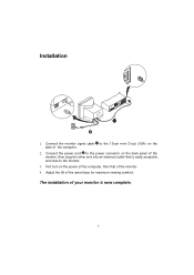
The installation of the computer. 2. Connect the monitor signal cable 1 to the 15-pin mini D-sub (VGA) on the back of your monitor is easily accessible, and close to the power connector on the power of the computer, then that is now complete. 7 Adjust the tilt of the monitor, then plug the other end into an electrical outlet that of the monitor. 4. Installation 1. Connect the power cord to the monitor. 3. First turn on the back panel of the swivel base for maximum viewing comfort.
The installation of the computer. 2. Connect the monitor signal cable 1 to the 15-pin mini D-sub (VGA) on the back of your monitor is easily accessible, and close to the power connector on the power of the computer, then that is now complete. 7 Adjust the tilt of the monitor, then plug the other end into an electrical outlet that of the monitor. 4. Installation 1. Connect the power cord to the monitor. 3. First turn on the back panel of the swivel base for maximum viewing comfort.
AC 501 User Guide
Page 8
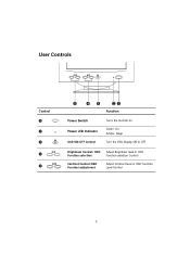
Sleep Turn the OSD Display ON or OFF Brightness Control/ OSD Adjust Brightness level or OSD Function selection Function selection Control Contrast Control/OSD Function adjustment Adjust Contract level or OSD Function Level Control 8 User Controls Control Power Switch Power LED Indicator OSD ON/OFF Control Function Turns the monitor on Green- On Amber-
Sleep Turn the OSD Display ON or OFF Brightness Control/ OSD Adjust Brightness level or OSD Function selection Function selection Control Contrast Control/OSD Function adjustment Adjust Contract level or OSD Function Level Control 8 User Controls Control Power Switch Power LED Indicator OSD ON/OFF Control Function Turns the monitor on Green- On Amber-
AC 501 User Guide
Page 10
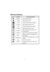
... Adjusts display brightness Adjusts display contrast Increases and decreases screen width Shifts display image right or left Increase and decrease screen height Shifts display image up or down Adjusts concave and convex portion of pincushion effect Adjusts the top and bottom display widths Adjusts the rotation of the display clock or anti-clockwise Adjusts the tilt of the display sides to the left or right Resets to default values Demagnetizes the screen to reduce color...
... Adjusts display brightness Adjusts display contrast Increases and decreases screen width Shifts display image right or left Increase and decrease screen height Shifts display image up or down Adjusts concave and convex portion of pincushion effect Adjusts the top and bottom display widths Adjusts the rotation of the display clock or anti-clockwise Adjusts the tilt of the display sides to the left or right Resets to default values Demagnetizes the screen to reduce color...
AC 501 User Guide
Page 11
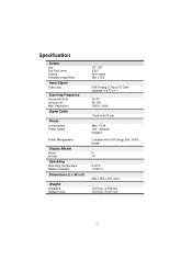
... 50-120 1280 x 1024 15-pin mini D-sub Max. 75 W 100 - 240VAC 50/60Hz Complies with EPA Energy Star ,VESA, Nutek 6 14 0-40°C 10-90 % 382 x 360 x 367 (mm) 12.5 Kgs (27.56 lbs) 14.5 Kgs (31.97 lbs) 11 Scanning Frequency Horizontal (KHz) Vertical (Hz) Max. Specification Screen Size Dot Pitch (mm) Surface Viewable Image Area Input Signal Video Sync.
... 50-120 1280 x 1024 15-pin mini D-sub Max. 75 W 100 - 240VAC 50/60Hz Complies with EPA Energy Star ,VESA, Nutek 6 14 0-40°C 10-90 % 382 x 360 x 367 (mm) 12.5 Kgs (27.56 lbs) 14.5 Kgs (31.97 lbs) 11 Scanning Frequency Horizontal (KHz) Vertical (Hz) Max. Specification Screen Size Dot Pitch (mm) Surface Viewable Image Area Input Signal Video Sync.

AC 501 User Guide
Page 12
... the power cord is connected properly. Problem: Display image is powered on. Problem: No display appears on the back of the manual for the failure symptoms that the computer switch is in a wave pattern. Make sure that the brightness and contrast controls are not turned to their dimmest position. Problem: Power LED is not lit when monitor is either flickering or unstable. Check to make sure that the video cable's D-shaped connector is connected properly to the video adapter port on...
... the power cord is connected properly. Problem: Display image is powered on. Problem: No display appears on the back of the manual for the failure symptoms that the computer switch is in a wave pattern. Make sure that the brightness and contrast controls are not turned to their dimmest position. Problem: Power LED is not lit when monitor is either flickering or unstable. Check to make sure that the video cable's D-shaped connector is connected properly to the video adapter port on...

AC501 Monitor Service Guide
Page 3
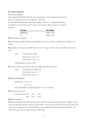
... horizontal and vertical size cont rols to get display size within speci fications as defined i n following Timing Mode Volt age Tol erance #1 31.5 KHz 66.7V ±3% #6 68.677 KHz 145V ±3% 3 Adjust VR901 to get a DC 145±0.3 V to proceed alignment. Equipments Signal generator: A chroma-2250 signal generator to be provided as standard color analyzer. CRT faces to east direction, connects monitor...
... horizontal and vertical size cont rols to get display size within speci fications as defined i n following Timing Mode Volt age Tol erance #1 31.5 KHz 66.7V ±3% #6 68.677 KHz 145V ±3% 3 Adjust VR901 to get a DC 145±0.3 V to proceed alignment. Equipments Signal generator: A chroma-2250 signal generator to be provided as standard color analyzer. CRT faces to east direction, connects monitor...
AC501 Monitor Service Guide
Page 4
... check x=281 +/-2 5 y=311 +/-2 5 Adjust SUB-Bright to get Color temperature 6500 x=313 y=329 5000 x=345 y=359 B-10. B-3. Select timing 6 VESA 1280X1024 with crosshatch pattern, adjust both horizontal and vertical OSD's size control to get full white pattern, Y is 0.06fl. Picture Alignment White balance alignment Select timing #6(VESA 64K 1280x1024) with full field raster pattern (cut off R, G, B) Adjust H-size 260mm V-size 195mm B-6. B-7: Select 2 inch one-square pattern, adjust color temperature 9300Celsius degree. Adjust...
... check x=281 +/-2 5 y=311 +/-2 5 Adjust SUB-Bright to get Color temperature 6500 x=313 y=329 5000 x=345 y=359 B-10. B-3. Select timing 6 VESA 1280X1024 with crosshatch pattern, adjust both horizontal and vertical OSD's size control to get full white pattern, Y is 0.06fl. Picture Alignment White balance alignment Select timing #6(VESA 64K 1280x1024) with full field raster pattern (cut off R, G, B) Adjust H-size 260mm V-size 195mm B-6. B-7: Select 2 inch one-square pattern, adjust color temperature 9300Celsius degree. Adjust...

AC501 Monitor Service Guide
Page 5
..., readjust 4 P and 6P on power again to get into burn-in mode and power saving check B-22. If raster center can't be adjust to obtain best focus performance. B-19. Turn off mode (power LED should indicating amber color), disconnect both H and V sync to verify X-ray protection circuit is working properly. Adjust H-size/ H-phase/V-size/V-center/ pincushion/trapezoid control s.... Disconnect P103 before automatic alignment or connect P103 before manual alignment. B-12.
..., readjust 4 P and 6P on power again to get into burn-in mode and power saving check B-22. If raster center can't be adjust to obtain best focus performance. B-19. Turn off mode (power LED should indicating amber color), disconnect both H and V sync to verify X-ray protection circuit is working properly. Adjust H-size/ H-phase/V-size/V-center/ pincushion/trapezoid control s.... Disconnect P103 before automatic alignment or connect P103 before manual alignment. B-12.
AC501 Monitor Service Guide
Page 14
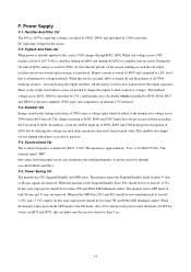
... is turned off and the polarity of 16V, U901 is determined by C906 to parasitic. Power Supply F-1. All the energy stored is smoothed by C911 and through R903, Q902.When t he divider which assembled by D901- When in the leakage inductance of CRT for the circuit. The monitor enters the Suspend/Standby mode if either V-sync or H-sync signals are removed...
... is turned off and the polarity of 16V, U901 is determined by C906 to parasitic. Power Supply F-1. All the energy stored is smoothed by C911 and through R903, Q902.When t he divider which assembled by D901- When in the leakage inductance of CRT for the circuit. The monitor enters the Suspend/Standby mode if either V-sync or H-sync signals are removed...
AC501 Monitor Service Guide
Page 25
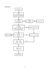
B-2 No picture No picture Check contrast & brightness control adjust to M AX. Check No input signal Check I/O cable Yes Check PC Check U301 PIN6 No vo;tage = 12VU301 PIN13 PULSE BLANKING Check Q201, D231 Check U301 No Check U301 PIN 14, 16, 19 output No Check connector Check C251 No voltage = 73VDC Check U303 PIN1, 2, 3 Check CRT 25
B-2 No picture No picture Check contrast & brightness control adjust to M AX. Check No input signal Check I/O cable Yes Check PC Check U301 PIN6 No vo;tage = 12VU301 PIN13 PULSE BLANKING Check Q201, D231 Check U301 No Check U301 PIN 14, 16, 19 output No Check connector Check C251 No voltage = 73VDC Check U303 PIN1, 2, 3 Check CRT 25

AC501 Monitor Service Guide
Page 39
...M570) 1EXPAND POWER SW 1POWER LED LENS(P554) 4RUBBER WASHER 1SCREW 4TAPPING SCREW 4SCREW 1PACKING ABO 1RATING NP-W/W 1CARTON 1USER'S MANUAL 2LABEL 1STATIC LABEL 1PE BAG (MONITOR) 1SWIVEL BASE&BALL ASS 1EPS FOAM(L) 1EPS FOAM(R) 1POWER CORD SET 1MECHANICAL PARTS 1BACK COVER(NONE USB) 1SPONGE 4TAPPING SCREW Line Level Part 1 1MP557G01004...5CC1000211T8 39 5CC1001011T1 Model AC501 (P557 Usage Description 1DIS ABO 1CRT & YOKE ASSY, 15C 1CRT&YOKE 1COIL SET 1DEGAUSSING COIL 1H-CON SET 1LOCKING CABLE TIE 1VIDEO ASSY 1PCBA, CRT BOARD 1AIS ASSY, CRT BOARD 1TRANSISTOR 3TRANSISTOR ...
...M570) 1EXPAND POWER SW 1POWER LED LENS(P554) 4RUBBER WASHER 1SCREW 4TAPPING SCREW 4SCREW 1PACKING ABO 1RATING NP-W/W 1CARTON 1USER'S MANUAL 2LABEL 1STATIC LABEL 1PE BAG (MONITOR) 1SWIVEL BASE&BALL ASS 1EPS FOAM(L) 1EPS FOAM(R) 1POWER CORD SET 1MECHANICAL PARTS 1BACK COVER(NONE USB) 1SPONGE 4TAPPING SCREW Line Level Part 1 1MP557G01004...5CC1000211T8 39 5CC1001011T1 Model AC501 (P557 Usage Description 1DIS ABO 1CRT & YOKE ASSY, 15C 1CRT&YOKE 1COIL SET 1DEGAUSSING COIL 1H-CON SET 1LOCKING CABLE TIE 1VIDEO ASSY 1PCBA, CRT BOARD 1AIS ASSY, CRT BOARD 1TRANSISTOR 3TRANSISTOR ...

AC501 Monitor Service Guide
Page 49
...M570) 1EXPAND POWER SW 1POWER LED LENS(P554) 4RUBBER WASHER 1SCREW 4TAPPING SCREW 4SCREW 1PACKING ABO 1RATING NP-W/W 1CARTON 1USER'S MANUAL 2LABEL 1STATIC LABEL 1PE BAG (MONITOR) 1SWIVEL BASE&BALL ASS 1EPS FOAM(L) 1EPS FOAM(R) 1PWR CORD 1MECHANICAL PARTS 1BACK COVER(NONE USB) 1SPONGE 4TAPPING SCREW Line Level Part 1 1MP557G01006 ... 5CA047ECK0T0 24 5CA082F601T6 Model AC501 (P557 Usage Description 1DIS ABO 1CRT & YOKE ASSY, 15C 1CRT&YOKE 1COIL SET 1DEGAUSSING COIL 1H-CON SET 1LOCKING CABLE TIE 1VIDEO ASSY 1PCBA, CRT BOARD 1AIS ASSY, CRT BOARD 1TRANSISTOR 3TRANSISTOR 6DIODE...
...M570) 1EXPAND POWER SW 1POWER LED LENS(P554) 4RUBBER WASHER 1SCREW 4TAPPING SCREW 4SCREW 1PACKING ABO 1RATING NP-W/W 1CARTON 1USER'S MANUAL 2LABEL 1STATIC LABEL 1PE BAG (MONITOR) 1SWIVEL BASE&BALL ASS 1EPS FOAM(L) 1EPS FOAM(R) 1PWR CORD 1MECHANICAL PARTS 1BACK COVER(NONE USB) 1SPONGE 4TAPPING SCREW Line Level Part 1 1MP557G01006 ... 5CA047ECK0T0 24 5CA082F601T6 Model AC501 (P557 Usage Description 1DIS ABO 1CRT & YOKE ASSY, 15C 1CRT&YOKE 1COIL SET 1DEGAUSSING COIL 1H-CON SET 1LOCKING CABLE TIE 1VIDEO ASSY 1PCBA, CRT BOARD 1AIS ASSY, CRT BOARD 1TRANSISTOR 3TRANSISTOR 6DIODE...

AC501 Monitor Service Guide
Page 54
...MANUAL 2LABEL 1STATIC LABEL 1PE BAG (MONITOR) 1SWIVEL BASE&BALL ASS 1EPS FOAM(L) 1EPS FOAM(R) 1MECHANICAL PARTS 1BACK COVER(NONE USB) 1SPONGE 4TAPPING SCREW Line Level Part 1 1MP557G01007 2 251A03500021 3 3AC500025510 4 3CL700001900 5 3CLA4M100106 6 3DC020132501 7 3KA000001ZZ4 8 251A03600009 9 3452A1800001 10 4442A1800001 11 5BB30945P1T5 12 5BBX042000T9 13 5BC101SS82T2 14 5BC11N4148T8 15 5BC1FR1040T0 16 5BC4HZ2720T5 17 5BC4HZ5C10T8 Model AC501... 1RELAY 1PUSH BUTTON SWITCH 1TRANSFORMER 1FUSE 2HEAT SINK 1HEAT SINK 1SCREW 1WIRE SET 2WIRE SET 1JUMPER WIRE ...
...MANUAL 2LABEL 1STATIC LABEL 1PE BAG (MONITOR) 1SWIVEL BASE&BALL ASS 1EPS FOAM(L) 1EPS FOAM(R) 1MECHANICAL PARTS 1BACK COVER(NONE USB) 1SPONGE 4TAPPING SCREW Line Level Part 1 1MP557G01007 2 251A03500021 3 3AC500025510 4 3CL700001900 5 3CLA4M100106 6 3DC020132501 7 3KA000001ZZ4 8 251A03600009 9 3452A1800001 10 4442A1800001 11 5BB30945P1T5 12 5BBX042000T9 13 5BC101SS82T2 14 5BC11N4148T8 15 5BC1FR1040T0 16 5BC4HZ2720T5 17 5BC4HZ5C10T8 Model AC501... 1RELAY 1PUSH BUTTON SWITCH 1TRANSFORMER 1FUSE 2HEAT SINK 1HEAT SINK 1SCREW 1WIRE SET 2WIRE SET 1JUMPER WIRE ...

AC501 Monitor Service Guide
Page 59
... BAG (MONITOR) 1SWIVEL BASE&BALL ASS 1EPS FOAM(L) 1EPS FOAM(R) 1MECHANICAL PARTS 1BACK COVER(NONE USB) 1SPONGE 4TAPPING SCREW Line Level Part 1 1MP557G01008 2 251A03500021 3 3AC500025510 4 3CL700001900 5 3CLA4M100106 6 3DC020132501 7 3KA000001ZZ4 8 251A03600009 9 3452A1800001 10 4442A1800001 Model AC501 (P557 Usage Description 1DIS ABO 1CRT & YOKE ASSY, 15C 1CRT&YOKE 1COIL SET 1DEGAUSSING COIL 1H-CON SET 1LOCKING CABLE TIE 1VIDEO ASSY 1PCBA, CRT BOARD 1AIS ASSY, CRT BOARD 59...
... BAG (MONITOR) 1SWIVEL BASE&BALL ASS 1EPS FOAM(L) 1EPS FOAM(R) 1MECHANICAL PARTS 1BACK COVER(NONE USB) 1SPONGE 4TAPPING SCREW Line Level Part 1 1MP557G01008 2 251A03500021 3 3AC500025510 4 3CL700001900 5 3CLA4M100106 6 3DC020132501 7 3KA000001ZZ4 8 251A03600009 9 3452A1800001 10 4442A1800001 Model AC501 (P557 Usage Description 1DIS ABO 1CRT & YOKE ASSY, 15C 1CRT&YOKE 1COIL SET 1DEGAUSSING COIL 1H-CON SET 1LOCKING CABLE TIE 1VIDEO ASSY 1PCBA, CRT BOARD 1AIS ASSY, CRT BOARD 59...

AC501 Monitor Service Guide
Page 75
...POWER SW 1 POWER LED LENS(P554) 4 RUBBER WASHER 1 SCREW 4 TAPPING SCREW 4 SCREW 1 PACKING ABO 1 RATING NP-W/W 1 CARTON 1 USER'S MANUAL 1 NOTICE SHEET 1 ENERGY STAR LABEL 2 TCO 95 LABEL 1 TCO 95 LABEL 1 PE BAG (MONITOR) 1 SWIVEL BASE&BALL ASS 1 EPS FOAM(L) 1 EPS FOAM(R) 1 PWR CORD 1 MECHANICAL PARTS 1 BACK COVER(NONE USB) 1 SPONGE 4 TAPPING SCREW Line Level Part...5 CC1002211T7 Model AC501 (P557) Usage Description 1 DIS ABO 1 CRT & YOKE ASSY, 15C 1 CRT&YOKE 1 COIL SET 1 DEGAUSSING COIL 1 H-CON SET 1 LOCKING CABLE TIE 1 VIDEO ASSY 1 PCBA, CRT BOARD 1 AIS ASSY, CRT BOARD 1 TRANSISTOR...
...POWER SW 1 POWER LED LENS(P554) 4 RUBBER WASHER 1 SCREW 4 TAPPING SCREW 4 SCREW 1 PACKING ABO 1 RATING NP-W/W 1 CARTON 1 USER'S MANUAL 1 NOTICE SHEET 1 ENERGY STAR LABEL 2 TCO 95 LABEL 1 TCO 95 LABEL 1 PE BAG (MONITOR) 1 SWIVEL BASE&BALL ASS 1 EPS FOAM(L) 1 EPS FOAM(R) 1 PWR CORD 1 MECHANICAL PARTS 1 BACK COVER(NONE USB) 1 SPONGE 4 TAPPING SCREW Line Level Part...5 CC1002211T7 Model AC501 (P557) Usage Description 1 DIS ABO 1 CRT & YOKE ASSY, 15C 1 CRT&YOKE 1 COIL SET 1 DEGAUSSING COIL 1 H-CON SET 1 LOCKING CABLE TIE 1 VIDEO ASSY 1 PCBA, CRT BOARD 1 AIS ASSY, CRT BOARD 1 TRANSISTOR...

AC501 Monitor Service Guide
Page 80
... BUTTON SWITCH 1 TRANSFORMER 1 FUSE 2 HEAT SINK 1 HEAT SINK 1 SCREW 1 WIRE SET 2 WIRE SET 1 JUMPER WIRE 1 HOUSING CONN. SET 1 CB ASY 1 BEZEL(ACR) 4 LOCKING CABLE TIE 1 WIRE SET 1 MECHANICAL ASSY 1 MYLAR 1 RETURN SPRING 1 PUSH KNOB(A)(P554) 1 PUSH KNOB(B)(P554) 1 POWER KNOB(P554) 1 PUSH KNOB(C) 1 PCB HOLDER-LCM870 1 PCB HOLDER-RCM570 1 EXPAND POWER SW 1 POWER LED LENS(P554) 4 RUBBER WASHER 1 SCREW 4 TAPPING SCREW 4 SCREW 1 PACKING ABO 1 RATING NP-W/W 1 CARTON 1 USER'S MANUAL...
... BUTTON SWITCH 1 TRANSFORMER 1 FUSE 2 HEAT SINK 1 HEAT SINK 1 SCREW 1 WIRE SET 2 WIRE SET 1 JUMPER WIRE 1 HOUSING CONN. SET 1 CB ASY 1 BEZEL(ACR) 4 LOCKING CABLE TIE 1 WIRE SET 1 MECHANICAL ASSY 1 MYLAR 1 RETURN SPRING 1 PUSH KNOB(A)(P554) 1 PUSH KNOB(B)(P554) 1 POWER KNOB(P554) 1 PUSH KNOB(C) 1 PCB HOLDER-LCM870 1 PCB HOLDER-RCM570 1 EXPAND POWER SW 1 POWER LED LENS(P554) 4 RUBBER WASHER 1 SCREW 4 TAPPING SCREW 4 SCREW 1 PACKING ABO 1 RATING NP-W/W 1 CARTON 1 USER'S MANUAL...

