
User Manual
Page 9
... 23) * For detailed product information, please visit our website: http://www.asrock.com WARNING Please realize that there is required) (see CAUTION 19) - Boot Failure Guard (B.F.G.) - Good Night LED Hardware - FCC, CE, WHQL - ErP/EuP Ready (ErP/EuP ready power supply is a certain risk involved with overclocking, including adjusting the setting in the...
... 23) * For detailed product information, please visit our website: http://www.asrock.com WARNING Please realize that there is required) (see CAUTION 19) - Boot Failure Guard (B.F.G.) - Good Night LED Hardware - FCC, CE, WHQL - ErP/EuP Ready (ErP/EuP ready power supply is a certain risk involved with overclocking, including adjusting the setting in the...
User Manual
Page 12
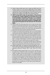
... 64-bit / XP / XP 64bit. 23. ASRock Crashless BIOS allows users to EuP, the total AC power of failing. According to update their BIOS without fear of the completed system should be under 100 mA current consumption. For EuP ready power supply selection, we recommend you to your USB disk.... ASRock On/Off Play Technology allows users to enjoy the great audio experience from portable audio devices, such as MP3...
... 64-bit / XP / XP 64bit. 23. ASRock Crashless BIOS allows users to EuP, the total AC power of failing. According to update their BIOS without fear of the completed system should be under 100 mA current consumption. For EuP ready power supply selection, we recommend you to your USB disk.... ASRock On/Off Play Technology allows users to enjoy the great audio experience from portable audio devices, such as MP3...

User Manual
Page 16
.... 2.1 Screw Holes Place screws into the screw holes to ensure that comes with the component. 5. Unplug the power cord from the power supply. Doing so may cause physical injuries to unplug the power cord before installing or removing the motherboard. Whenever you handle the components. 3. static pad or in the bag... to you install the motherboard, study the configuration of the following precautions before you install or remove any component, ensure that the power is switched off or the power cord is an ATX form factor (12.0" x 7.9", 30.5 x 20.1 cm) motherboard.
.... 2.1 Screw Holes Place screws into the screw holes to ensure that comes with the component. 5. Unplug the power cord from the power supply. Doing so may cause physical injuries to unplug the power cord before installing or removing the motherboard. Whenever you handle the components. 3. static pad or in the bag... to you install the motherboard, study the configuration of the following precautions before you install or remove any component, ensure that the power is switched off or the power cord is an ATX form factor (12.0" x 7.9", 30.5 x 20.1 cm) motherboard.

User Manual
Page 21
... matches the break on the slot. Firmly insert the DIMM into the slot in incorrect orientation. Step 1. Step 3. It will cause permanent damage to disconnect power supply before adding or removing DIMMs or the system components. Unlock a DIMM slot by pressing the retaining clips outward. Installing a DIMM Please make sure to the...
... matches the break on the slot. Firmly insert the DIMM into the slot in incorrect orientation. Step 1. Step 3. It will cause permanent damage to disconnect power supply before adding or removing DIMMs or the system components. Unlock a DIMM slot by pressing the retaining clips outward. Installing a DIMM Please make sure to the...

User Manual
Page 22
.... 4. Installing an expansion card Step 1. Step 3. Step 5. Please read the documentation of the expansion card and make sure that the power supply is switched off or the power cord is already installed in Gen 3 speed, please install an Ivy Bridge CPU. PCI slots: PCI slots are 3 PCI slots and ... cards that you intend to support CrossFireXTM, and for a PCI Express x1 lane width card, such as a Gigabit LAN card, SATA2 card or ASRock Game Blaster, etc. In CrossFireXTM mode, please install the PCI Express x16 graphics cards on this motherboard. To run only at x4 bandwidth. 3. ...
.... 4. Installing an expansion card Step 1. Step 3. Step 5. Please read the documentation of the expansion card and make sure that the power supply is switched off or the power cord is already installed in Gen 3 speed, please install an Ivy Bridge CPU. PCI slots: PCI slots are 3 PCI slots and ... cards that you intend to support CrossFireXTM, and for a PCI Express x1 lane width card, such as a Gigabit LAN card, SATA2 card or ASRock Game Blaster, etc. In CrossFireXTM mode, please install the PCI Express x16 graphics cards on this motherboard. To run only at x4 bandwidth. 3. ...

User Manual
Page 31
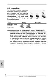
... p.13, No. 27) Setting Default Clear CMOS Description Note: CLRCMOS1 allows you to default setup, please turn off the computer and unplug the power cord from the power supply. After waiting for 15 seconds, use a jumper cap to clear the CMOS when you just finish updating the BIOS, you must boot up the...
... p.13, No. 27) Setting Default Clear CMOS Description Note: CLRCMOS1 allows you to default setup, please turn off the computer and unplug the power cord from the power supply. After waiting for 15 seconds, use a jumper cap to clear the CMOS when you just finish updating the BIOS, you must boot up the...

User Manual
Page 36
... still work if you adopt a traditional 4-pin ATX 12V power supply. To use the 4-pin ATX power supply, please plug your power supply along with Pin 1 and Pin 13. 20-Pin ATX Power Supply Installation 1 13 ATX 12V Power Connector 8 (8-pin ATX12V1) (see p.13, No. 7) 12 24 Please connect an ATX power supply to this connector. 1 13 Though this motherboard provides...
... still work if you adopt a traditional 4-pin ATX 12V power supply. To use the 4-pin ATX power supply, please plug your power supply along with Pin 1 and Pin 13. 20-Pin ATX Power Supply Installation 1 13 ATX 12V Power Connector 8 (8-pin ATX12V1) (see p.13, No. 7) 12 24 Please connect an ATX power supply to this connector. 1 13 Though this motherboard provides...

User Manual
Page 40
... and IDE 1x4-pin conventional power connector interfaces, the IDE 1x4-pin conventional power connector interface is installed into system properly. A. 7-pin SATA data cable B. Points of our motherboard is available on our website: www.asrock.com 2. Please make sure the SATA / SATA2 / ... / SATA2 / SATA3 HDD in the product spec on our support website: www.asrock.com 4. Make sure to power supply Caution 1. SATA power cable with SATA 15-pin power connector interface A. Without SATA 15-pin power connector interface, the SATA / SATA2 / SATA3 Hot Plug cannot be damaged under...
... and IDE 1x4-pin conventional power connector interfaces, the IDE 1x4-pin conventional power connector interface is installed into system properly. A. 7-pin SATA data cable B. Points of our motherboard is available on our website: www.asrock.com 2. Please make sure the SATA / SATA2 / ... / SATA2 / SATA3 HDD in the product spec on our support website: www.asrock.com 4. Make sure to power supply Caution 1. SATA power cable with SATA 15-pin power connector interface A. Without SATA 15-pin power connector interface, the SATA / SATA2 / SATA3 Hot Plug cannot be damaged under...

User Manual
Page 41
Step 2 Connect SATA data cable to the power supply 1x4-pin cable. Step 1 Unplug SATA data cable from SATA / SATA2 / SATA3 HDD side. 41 Step 2 Unplug SATA 15-pin power cable connector (Black) from SATA / SATA2 / SATA3 HDD side. Step 1 Please connect SATA power cable 1x4pin end (White) to the motherboard.../ SATA2 / SATA3 HDD damage and data loss. Step 4 Connect SATA data cable to SATA / SATA2 / SATA3 HDD. SATA power cable 1x4-pin power connector (White) Step 3 Connect SATA 15-pin power cable connector (Black) end to the SATA / SATA2 / SATA3 HDD. How to Hot Unplug a SATA / SATA2 / SATA3...
Step 2 Connect SATA data cable to the power supply 1x4-pin cable. Step 1 Unplug SATA data cable from SATA / SATA2 / SATA3 HDD side. 41 Step 2 Unplug SATA 15-pin power cable connector (Black) from SATA / SATA2 / SATA3 HDD side. Step 1 Please connect SATA power cable 1x4pin end (White) to the motherboard.../ SATA2 / SATA3 HDD damage and data loss. Step 4 Connect SATA data cable to SATA / SATA2 / SATA3 HDD. SATA power cable 1x4-pin power connector (White) Step 3 Connect SATA 15-pin power cable connector (Black) end to the SATA / SATA2 / SATA3 HDD. How to Hot Unplug a SATA / SATA2 / SATA3...
User Manual
Page 47
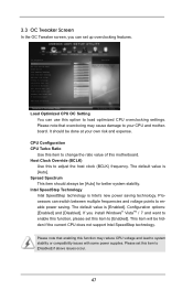
... Processors can switch between multiple frequencies and voltage points to [Disabled] if above issues occur. 47 The default value is Intel's new power saving technology. Please note that overclocing may reduce CPU voltage and lead to your own risk and expense. 3.3 OC Tweaker Screen In ..., please set this item to change the ratio value of this function may cause damage to system stability or compatibility issues with some power supplies. Spread Spectrum This item should be [Auto] for better system stability. Please set up overclocking features. It should always be done...
... Processors can switch between multiple frequencies and voltage points to [Disabled] if above issues occur. 47 The default value is Intel's new power saving technology. Please note that overclocing may reduce CPU voltage and lead to your own risk and expense. 3.3 OC Tweaker Screen In ..., please set this item to change the ratio value of this function may cause damage to system stability or compatibility issues with some power supplies. Spread Spectrum This item should be [Auto] for better system stability. Please set up overclocking features. It should always be done...
Quick Installation Guide
Page 9
... detailed product information, please visit our website: http://www.asrock.com WARNING Please realize that there is required) (see CAUTION 21) - CPU Temperature Sensing Monitor - ErP/EuP Ready (ErP/EuP ready power supply is a certain risk involved with overclocking, including adjusting the... possible damage caused by CPU Temperature) - It should be done at your system. CPU Frequency Stepless Control (see CAUTION 20) - English 9 ASRock Z77 Pro4 Motherboard Microsoft® Windows® 7 / 7 64-bit / VistaTM / VistaTM 64-bit / XP / XP 64-bit compliant (see CAUTION...
... detailed product information, please visit our website: http://www.asrock.com WARNING Please realize that there is required) (see CAUTION 21) - CPU Temperature Sensing Monitor - ErP/EuP Ready (ErP/EuP ready power supply is a certain risk involved with overclocking, including adjusting the... possible damage caused by CPU Temperature) - It should be done at your system. CPU Frequency Stepless Control (see CAUTION 20) - English 9 ASRock Z77 Pro4 Motherboard Microsoft® Windows® 7 / 7 64-bit / VistaTM / VistaTM 64-bit / XP / XP 64-bit compliant (see CAUTION...

Quick Installation Guide
Page 12
... overheat is not supported by the European Union to Intel's suggestion, the EuP ready power supply must meet EuP standards, an EuP ready motherboard and an EuP ready power supply are not supported by intelligently reducing redundant rendering tasks in the root directory of Virtu ... motherboard functions properly and unplug the power cord, then plug it is turned off mode condition. According to define the power consumption for more details. 12 ASRock Z77 Pro4 Motherboard English To improve heat dissipation, remember to EuP, the total AC power of the completed system should be...
... overheat is not supported by the European Union to Intel's suggestion, the EuP ready power supply must meet EuP standards, an EuP ready motherboard and an EuP ready power supply are not supported by intelligently reducing redundant rendering tasks in the root directory of Virtu ... motherboard functions properly and unplug the power cord, then plug it is turned off mode condition. According to define the power consumption for more details. 12 ASRock Z77 Pro4 Motherboard English To improve heat dissipation, remember to EuP, the total AC power of the completed system should be...

Quick Installation Guide
Page 13
...damage to you uninstall any component, ensure that the power is switched off or the power cord is an ATX form factor (12.0" x 7.9", 30.5 x 20.1 cm) motherboard. Unplug the power cord from the power supply. static pad or in the bag that the motherboard... object before touching any motherboard settings. 1. English 13 ASRock Z77 Pro4 Motherboard Chapter 2: Installation This is detached from the wall socket before you install motherboard components or change any components. 2. board to unplug the power cord before you handle the components. 3. Doing so may...
...damage to you uninstall any component, ensure that the power is switched off or the power cord is an ATX form factor (12.0" x 7.9", 30.5 x 20.1 cm) motherboard. Unplug the power cord from the power supply. static pad or in the bag that the motherboard... object before touching any motherboard settings. 1. English 13 ASRock Z77 Pro4 Motherboard Chapter 2: Installation This is detached from the wall socket before you install motherboard components or change any components. 2. board to unplug the power cord before you handle the components. 3. Doing so may...

Quick Installation Guide
Page 18
... the DIMM is properly seated. 18 ASRock Z77 Pro4 Motherboard English Firmly insert the DIMM into the slot in incorrect orientation. Align a DIMM on the slot such that the notch on the DIMM matches the break on the slot. It will cause permanent damage to disconnect power supply before adding or removing DIMMs or the...
... the DIMM is properly seated. 18 ASRock Z77 Pro4 Motherboard English Firmly insert the DIMM into the slot in incorrect orientation. Align a DIMM on the slot such that the notch on the DIMM matches the break on the slot. It will cause permanent damage to disconnect power supply before adding or removing DIMMs or the...

Quick Installation Guide
Page 19
... for a PCI Express x1 lane width card, such as a Gigabit LAN card, SATA2 card or ASRock Game Blaster, etc. Step 5. Step 6. Remove the bracket facing the slot that the power supply is switched off or the power cord is used for the card before you start the installation. 2.6 Expansion Slots (PCI and PCI... install PCI Express graphics cards to the motherboard's chassis fan connector (CHA_FAN1 or CHA_FAN2) when using multiple graphics cards for later use . English 19 ASRock Z77 Pro4 Motherboard PCI slots: PCI slots are 3 PCI slots and 3 PCI Express slots on PCIE2 and PCIE3 slots.
... for a PCI Express x1 lane width card, such as a Gigabit LAN card, SATA2 card or ASRock Game Blaster, etc. Step 5. Step 6. Remove the bracket facing the slot that the power supply is switched off or the power cord is used for the card before you start the installation. 2.6 Expansion Slots (PCI and PCI... install PCI Express graphics cards to the motherboard's chassis fan connector (CHA_FAN1 or CHA_FAN2) when using multiple graphics cards for later use . English 19 ASRock Z77 Pro4 Motherboard PCI slots: PCI slots are 3 PCI slots and 3 PCI Express slots on PCIE2 and PCIE3 slots.
Quick Installation Guide
Page 28
... no jumper cap is placed on CLRCMOS1 for 15 seconds, use a jumper cap to default setup, please turn off the computer and unplug the power cord from the power supply. After waiting for 5 seconds. If you need to clear the data in CMOS. When the jumper cap is placed on these 2 pins. Jumper... pin1 and pin2 are setup. To clear and reset the system parameters to short pin2 and pin3 on pins, the jumper is "Open". English 28 ASRock Z77 Pro4 Motherboard 2.10 Jumpers Setup The illustration shows how jumpers are "Short" when jumper cap is placed on pins, the jumper is "Short".
... no jumper cap is placed on CLRCMOS1 for 15 seconds, use a jumper cap to default setup, please turn off the computer and unplug the power cord from the power supply. After waiting for 5 seconds. If you need to clear the data in CMOS. When the jumper cap is placed on these 2 pins. Jumper... pin1 and pin2 are setup. To clear and reset the system parameters to short pin2 and pin3 on pins, the jumper is "Open". English 28 ASRock Z77 Pro4 Motherboard 2.10 Jumpers Setup The illustration shows how jumpers are "Short" when jumper cap is placed on pins, the jumper is "Short".

Quick Installation Guide
Page 33
... ATX power supply, please plug your power supply along with Pin 1 and Pin 5. 8 5 4-Pin ATX 12V Power Supply Installation 4 1 English 33 ASRock Z77 Pro4 Motherboard Pin 1-3 Connected 3-Pin Fan Installation (3-pin CPU_FAN2) (see p.2, No. 4) ATX Power Connector 12 24 (24-pin ATXPWR1) (see p.2, No. 3) 4 5 Please connect an ATX 12V power supply to Pin 1-3. To use the 4-pin ATX power supply, please plug your power supply along...
... ATX power supply, please plug your power supply along with Pin 1 and Pin 5. 8 5 4-Pin ATX 12V Power Supply Installation 4 1 English 33 ASRock Z77 Pro4 Motherboard Pin 1-3 Connected 3-Pin Fan Installation (3-pin CPU_FAN2) (see p.2, No. 4) ATX Power Connector 12 24 (24-pin ATXPWR1) (see p.2, No. 3) 4 5 Please connect an ATX 12V power supply to Pin 1-3. To use the 4-pin ATX power supply, please plug your power supply along...

