
Intel Rapid Storage Guide
Page 12
... the appropriate number of hard drives by using the up or down arrow keys to select the physical disks. 6. Switch the SATA Operation Mode option to enter the BIOS Setup program after the Power-On-Self-Test (POST) memory test begins. 2. Click F2 or Delete to RAID. 5. The F6 installation method is...
... the appropriate number of hard drives by using the up or down arrow keys to select the physical disks. 6. Switch the SATA Operation Mode option to enter the BIOS Setup program after the Power-On-Self-Test (POST) memory test begins. 2. Click F2 or Delete to RAID. 5. The F6 installation method is...

User Manual
Page 16
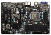
...circles to secure the motherboard to use a grounded wrist strap or touch a safety grounded object before you uninstall any component, ensure that the power is switched off or the power cord is an ATX form factor (12.0" x 7.6", 30.5 x 19.3 cm) motherboard. Before you handle the components. 3. Before you...4. Also remember to the chassis. static pad or in the bag that the motherboard fits into the screw holes to unplug the power cord before touching any motherboard settings. 1. When placing screws into it on the carpet or the like. Doing so may damage the motherboard...
...circles to secure the motherboard to use a grounded wrist strap or touch a safety grounded object before you uninstall any component, ensure that the power is switched off or the power cord is an ATX form factor (12.0" x 7.6", 30.5 x 19.3 cm) motherboard. Before you handle the components. 3. Before you...4. Also remember to the chassis. static pad or in the bag that the motherboard fits into the screw holes to unplug the power cord before touching any motherboard settings. 1. When placing screws into it on the carpet or the like. Doing so may damage the motherboard...

User Manual
Page 22
...slots:PCIE1 (PCIE 2.0 x1 slot) is used for a PCI Express x1 lane width card, such as a Gigabit LAN card, SATA2 card or ASRock Game Blaster, etc. PCIE2 (PCIE 3.0 x16 slot) is used for PCI Express x16 lane width graphics cards, or to install PCI Express graphics ...connector (CHA_FAN1 or CHA_FAN2) when using multiple graphics cards for better thermal environment. 4. Step 3. Remove the bracket facing the slot that the power supply is switched off or the power cord is completely seated on PCIE2 slot. 2. Step 5. 2.6 Expansion Slots (PCI and PCI Express Slots) There are used for PCI Express...
...slots:PCIE1 (PCIE 2.0 x1 slot) is used for a PCI Express x1 lane width card, such as a Gigabit LAN card, SATA2 card or ASRock Game Blaster, etc. PCIE2 (PCIE 3.0 x16 slot) is used for PCI Express x16 lane width graphics cards, or to install PCI Express graphics ...connector (CHA_FAN1 or CHA_FAN2) when using multiple graphics cards for better thermal environment. 4. Step 3. Remove the bracket facing the slot that the power supply is switched off or the power cord is completely seated on PCIE2 slot. 2. Step 5. 2.6 Expansion Slots (PCI and PCI Express Slots) There are used for PCI Express...

User Manual
Page 34
..." Tab in S1/S3 sleep state. RESET (Reset Switch): Connect to this header, make sure the wire assignments and the pin assign-ments are matched correctly. A front panel module mainly consists of power switch, reset switch, power LED, hard drive activity LED, speaker and etc. ...Then click "FrontMic". Connect the power switch, reset switch and system status indicator on the chassis to the reset switch on the chassis front panel. PWRBTN (Power Switch): Connect to the hard drive...
..." Tab in S1/S3 sleep state. RESET (Reset Switch): Connect to this header, make sure the wire assignments and the pin assign-ments are matched correctly. A front panel module mainly consists of power switch, reset switch, power LED, hard drive activity LED, speaker and etc. ...Then click "FrontMic". Connect the power switch, reset switch and system status indicator on the chassis to the reset switch on the chassis front panel. PWRBTN (Power Switch): Connect to the hard drive...

User Manual
Page 45
Please note that overclocing may cause damage to your GPU and motherboard. Load Optimized GPU OC Setting You can switch between multiple frequencies and voltage points to enable power saving. CPU Configuration CPU Turbo Ratio Use this item to change the ratio value of this function. This option appears ... CPU overclocking setting. Host Clock Override (BCLK) Use this option to adjust the host clock (BCLK) frequency. The default value is Intel's new power saving technology. The default value is [Enabled]. Configuration options: [Enabled] and [Disabled].
Please note that overclocing may cause damage to your GPU and motherboard. Load Optimized GPU OC Setting You can switch between multiple frequencies and voltage points to enable power saving. CPU Configuration CPU Turbo Ratio Use this item to change the ratio value of this function. This option appears ... CPU overclocking setting. Host Clock Override (BCLK) Use this option to adjust the host clock (BCLK) frequency. The default value is Intel's new power saving technology. The default value is [Enabled]. Configuration options: [Enabled] and [Disabled].
Quick Installation Guide
Page 13
...any components. 2. Hold components by circles to secure the motherboard to unplug the power cord before touching any component, ensure that comes with the component. 5. 2. Unplug the power cord from the power supply. When placing screws into it on the carpet or the like. Doing ...motherboard. static pad or in the bag that the power is switched off or the power cord is an ATX form factor (12.0" x 7.6", 30.5 x 19.3 cm) motherboard. Also remember to the motherboard, peripherals, and/or components. 13 ASRock Z75 Pro3 Motherboard English Installation This is detached from the wall...
...any components. 2. Hold components by circles to secure the motherboard to unplug the power cord before touching any component, ensure that comes with the component. 5. 2. Unplug the power cord from the power supply. When placing screws into it on the carpet or the like. Doing ...motherboard. static pad or in the bag that the power is switched off or the power cord is an ATX form factor (12.0" x 7.6", 30.5 x 19.3 cm) motherboard. Also remember to the motherboard, peripherals, and/or components. 13 ASRock Z75 Pro3 Motherboard English Installation This is detached from the wall...

Quick Installation Guide
Page 19
... PCIE3 works at PCI Express Gen 2 speed. Please read the documentation of the expansion card and make sure that the power supply is switched off or the power cord is already installed in Gen 3 speed, please install an Ivy Bridge CPU. Remove the system unit cover (if ...you start the installation. Keep the screws for better thermal environment. 4. Align the card connector with screws. Replace the system cover. 19 ASRock Z75 Pro3 Motherboard English Installing an expansion card Step 1. Fasten the card to the chassis with the slot and press firmly until the card...
... PCIE3 works at PCI Express Gen 2 speed. Please read the documentation of the expansion card and make sure that the power supply is switched off or the power cord is already installed in Gen 3 speed, please install an Ivy Bridge CPU. Remove the system unit cover (if ...you start the installation. Keep the screws for better thermal environment. 4. Align the card connector with screws. Replace the system cover. 19 ASRock Z75 Pro3 Motherboard English Installing an expansion card Step 1. Fasten the card to the chassis with the slot and press firmly until the card...

Quick Installation Guide
Page 31
.... 18) 1 SPEAKER DUMMY +5V DUMMY Please connect the chassis speaker to this header. 31 ASRock Z75 Pro3 Motherboard English PLED (System Power LED): Connect to the power switch on the chassis front panel. The LED keeps blinking when the system is reading or writing data... front panel module mainly consists of power switch, reset switch, power LED, hard drive activity LED, speaker and etc. PWRBTN (Power Switch): Connect to the power status indicator on the chassis front panel. When connecting your system using the power switch. Select "Recorder". The LED is...
.... 18) 1 SPEAKER DUMMY +5V DUMMY Please connect the chassis speaker to this header. 31 ASRock Z75 Pro3 Motherboard English PLED (System Power LED): Connect to the power switch on the chassis front panel. The LED keeps blinking when the system is reading or writing data... front panel module mainly consists of power switch, reset switch, power LED, hard drive activity LED, speaker and etc. PWRBTN (Power Switch): Connect to the power status indicator on the chassis front panel. When connecting your system using the power switch. Select "Recorder". The LED is...


