
User Manual
Page 7
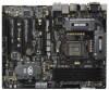
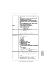
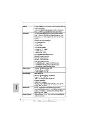
resolution up to -Use USB 3.0 Ports - 1 x RJ-45 LAN Port with LED (ACT/LINK LED and SPEED LED) - 1 x IEEE 1394 Port - 1 x Clear CMOS Switch with HDMI (Compliant HDMI monitor is required) (see CAUTION 8) - 2 x SATA3 6.0 Gb/s connectors, support RAID (RAID 0, RAID 1, RAID 10, RAID 5, Intel Rapid Storage and Intel ...
resolution up to -Use USB 3.0 Ports - 1 x RJ-45 LAN Port with LED (ACT/LINK LED and SPEED LED) - 1 x IEEE 1394 Port - 1 x Clear CMOS Switch with HDMI (Compliant HDMI monitor is required) (see CAUTION 8) - 2 x SATA3 6.0 Gb/s connectors, support RAID (RAID 0, RAID 1, RAID 10, RAID 5, Intel Rapid Storage and Intel ...
User Manual
Page 8
..., PCH, CPU PLL, VTT, VCCSA Voltage Multi-adjustment - OEM) - ASRock Instant Boot 8 ACPI 1.1 Compliance Wake Up Events - ASRock Extreme Tuning Utility (AXTU) (see CAUTION 9) - Front panel audio connector - 3 x USB 2.0 headers (support 6 USB 2.0 ports) - 1 x USB 3.0 header (supports 2 USB 3.0 ports) - 1 x Dr. Debug (7-Segment Debug LED) - 1 x Clear CMOS Switch with LED - 1 x Power Switch with LED - 1 x Reset Switch...
..., PCH, CPU PLL, VTT, VCCSA Voltage Multi-adjustment - OEM) - ASRock Instant Boot 8 ACPI 1.1 Compliance Wake Up Events - ASRock Extreme Tuning Utility (AXTU) (see CAUTION 9) - Front panel audio connector - 3 x USB 2.0 headers (support 6 USB 2.0 ports) - 1 x USB 3.0 header (supports 2 USB 3.0 ports) - 1 x Dr. Debug (7-Segment Debug LED) - 1 x Clear CMOS Switch with LED - 1 x Power Switch with LED - 1 x Reset Switch...

User Manual
Page 13
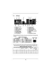
...HD_AUDIO1 1 HDMI_SPDIF1 COM1 1 1 PCIE2 RoHS PCIE3 PCI Express 3.0 PCI1 Z68 Extreme4 Gen3 CMOS Battery PCIE4 XFast USB PCI2 DX10.1 Front USB 3.0 1394a FLOPPY1 PCIE5 IR1 1 FRONT_1394 1 USB6_7 1 1 CIR1 USB8_9 1 Intel Z68 SATA2_4_5 64Mb BIOS RSTBTN Dr. Debug USB10_11 1 USB3_12_13 PWRBTN PLED1 1... 8 ATX Power Connector (ATXPWR1) 33 Infrared Module Header (IR1) 9 Chassis Fan Connector (CHA_FAN1) 34 Floppy Connector (FLOPPY1) 10 Clear CMOS Jumper (CLRCMOS1) 35 COM Port Header (COM1) 11 SATA3 Connector (SATA3_M1, Gray) 36 Front Panel Audio Header 12 SATA3 Connector (...
...HD_AUDIO1 1 HDMI_SPDIF1 COM1 1 1 PCIE2 RoHS PCIE3 PCI Express 3.0 PCI1 Z68 Extreme4 Gen3 CMOS Battery PCIE4 XFast USB PCI2 DX10.1 Front USB 3.0 1394a FLOPPY1 PCIE5 IR1 1 FRONT_1394 1 USB6_7 1 1 CIR1 USB8_9 1 Intel Z68 SATA2_4_5 64Mb BIOS RSTBTN Dr. Debug USB10_11 1 USB3_12_13 PWRBTN PLED1 1... 8 ATX Power Connector (ATXPWR1) 33 Infrared Module Header (IR1) 9 Chassis Fan Connector (CHA_FAN1) 34 Floppy Connector (FLOPPY1) 10 Clear CMOS Jumper (CLRCMOS1) 35 COM Port Header (COM1) 11 SATA3 Connector (SATA3_M1, Gray) 36 Front Panel Audio Header 12 SATA3 Connector (...
User Manual
Page 14
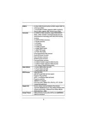
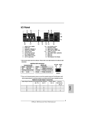
... Blue) ** 10 11 12 13 *** 14 15 16 17 18 Front Speaker (Lime) Microphone (Pink) USB 3.0 Ports (USB45) IEEE 1394 Port (IEEE 1394) eSATA3 Connector Clear CMOS Switch (CLRCBTN) HDMI Port DVI-D Port PS/2 Keyboard Port (Purple) * There are two LED next to the table below for connection details in accordance with...
... Blue) ** 10 11 12 13 *** 14 15 16 17 18 Front Speaker (Lime) Microphone (Pink) USB 3.0 Ports (USB45) IEEE 1394 Port (IEEE 1394) eSATA3 Connector Clear CMOS Switch (CLRCBTN) HDMI Port DVI-D Port PS/2 Keyboard Port (Purple) * There are two LED next to the table below for connection details in accordance with...

User Manual
Page 37
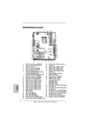
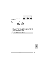
...for 15 seconds, use a jumper cap to short pin2 and pin3 on these 2 pins. However, please do the clear-CMOS action. Jumper Clear CMOS Jumper (CLRCMOS1) (see p.13, No. 10) Setting Default Clear CMOS Description Note: CLRCMOS1 allows you update the BIOS. The illustration shows a 3-pin jumper whose pin1 and pin2 are ...setup. The Clear CMOS Switch has the same function as the Clear CMOS jumper. 37 When the jumper cap is placed on pins, the jumper is placed on CLRCMOS1 for 5 seconds. If you need to clear the CMOS when you just nish updating the BIOS, you ...
...for 15 seconds, use a jumper cap to short pin2 and pin3 on these 2 pins. However, please do the clear-CMOS action. Jumper Clear CMOS Jumper (CLRCMOS1) (see p.13, No. 10) Setting Default Clear CMOS Description Note: CLRCMOS1 allows you update the BIOS. The illustration shows a 3-pin jumper whose pin1 and pin2 are ...setup. The Clear CMOS Switch has the same function as the Clear CMOS jumper. 37 When the jumper cap is placed on pins, the jumper is placed on CLRCMOS1 for 5 seconds. If you need to clear the CMOS when you just nish updating the BIOS, you ...

User Manual
Page 44
... motherboard. Step 5 Plug the Front USB 3.0 cable into the USB 3.0 Step 6 The Front USB 3.0 Panel is ready to quickly clear the CMOS values. 44 Clear CMOS Switch (CLRCBTN) (see p.13 No. 21) RESET Reset Switch is a smart switch, allowing users to use. Step 3 Screw the...two screws into the rear USB 3.0 bracket. header (USB3_12_13) on /off or reset the sytem clear the CMOS values. USB 3.0 bracket together. Reset Switch (RSTBTN) (see p.14 No. 15) clr CMOS Clear CMOS Switch is a smart switch, allowing users to quickly reset the system. The Installation Guide of Rear...
... motherboard. Step 5 Plug the Front USB 3.0 cable into the USB 3.0 Step 6 The Front USB 3.0 Panel is ready to quickly clear the CMOS values. 44 Clear CMOS Switch (CLRCBTN) (see p.13 No. 21) RESET Reset Switch is a smart switch, allowing users to use. Step 3 Screw the...two screws into the rear USB 3.0 bracket. header (USB3_12_13) on /off or reset the sytem clear the CMOS values. USB 3.0 bracket together. Reset Switch (RSTBTN) (see p.14 No. 15) clr CMOS Clear CMOS Switch is a smart switch, allowing users to quickly reset the system. The Installation Guide of Rear...
Quick Installation Guide
Page 2
... Channel: DDR3_A2, DDR3_B2, Black) (FRONT_1394, Black) 8 ATX Power Connector (ATXPWR1) 33 Infrared Module Header (IR1) 9 Chassis Fan Connector (CHA_FAN1) 34 Floppy Connector (FLOPPY1) 10 Clear CMOS Jumper (CLRCMOS1) 35 COM Port Header (COM1) 11 SATA3 Connector (SATA3_M1, Gray) 36 Front Panel Audio Header 12 SATA3 Connector (SATA3_M2, Gray) (HD_AUDIO1, Black) 13... Header (PLED1) 46 Chassis Fan Connector (CHA_FAN3) 24 System Panel Header (PANEL1, Black) 47 Chassis Fan Connector (CHA_FAN2) 25 Chassis Speaker Header (SPEAKER 1, Black) 2 ASRock Z68 Extreme4 Gen3 Motherboard English
... Channel: DDR3_A2, DDR3_B2, Black) (FRONT_1394, Black) 8 ATX Power Connector (ATXPWR1) 33 Infrared Module Header (IR1) 9 Chassis Fan Connector (CHA_FAN1) 34 Floppy Connector (FLOPPY1) 10 Clear CMOS Jumper (CLRCMOS1) 35 COM Port Header (COM1) 11 SATA3 Connector (SATA3_M1, Gray) 36 Front Panel Audio Header 12 SATA3 Connector (SATA3_M2, Gray) (HD_AUDIO1, Black) 13... Header (PLED1) 46 Chassis Fan Connector (CHA_FAN3) 24 System Panel Header (PANEL1, Black) 47 Chassis Fan Connector (CHA_FAN2) 25 Chassis Speaker Header (SPEAKER 1, Black) 2 ASRock Z68 Extreme4 Gen3 Motherboard English
Quick Installation Guide
Page 3
...Rear Speaker Central / Bass Line In or (No. 10) (No. 7) (No. 6) Side Speaker (No. 9) 2 V -- -- -- 4 V V -- -- 6 V V V -- 8 V V V V English 3 ASRock Z68 Extreme4 Gen3 Motherboard Please refer to the LAN port. I/O Panel 12 3 45 69 7 10 8 11 18 17 16 15 14 13 12 1 USB 2.0 Ports (USB01) 2 D-Sub Port... 14 15 16 17 18 Front Speaker (Lime) Microphone (Pink) USB 3.0 Ports (USB45) IEEE 1394 Port (IEEE 1394) eSATA3 Connector Clear CMOS Switch (CLRCBTN) HDMI Port DVI-D Port PS/2 Keyboard Port (Purple) * There are two LED next to the table below for connection ...
...Rear Speaker Central / Bass Line In or (No. 10) (No. 7) (No. 6) Side Speaker (No. 9) 2 V -- -- -- 4 V V -- -- 6 V V V -- 8 V V V V English 3 ASRock Z68 Extreme4 Gen3 Motherboard Please refer to the LAN port. I/O Panel 12 3 45 69 7 10 8 11 18 17 16 15 14 13 12 1 USB 2.0 Ports (USB01) 2 D-Sub Port... 14 15 16 17 18 Front Speaker (Lime) Microphone (Pink) USB 3.0 Ports (USB45) IEEE 1394 Port (IEEE 1394) eSATA3 Connector Clear CMOS Switch (CLRCBTN) HDMI Port DVI-D Port PS/2 Keyboard Port (Purple) * There are two LED next to the table below for connection ...
Quick Installation Guide
Page 7
... NCQ, AHCI and "Hot Plug" functions (SATA3_M2 connector is shared with eSATA3 port) English 7 ASRock Z68 Extreme4 Gen3 Motherboard resolution up to -Use USB 3.0 Ports - 1 x RJ-45 LAN Port with LED (ACT/LINK LED and SPEED LED) - 1 x IEEE 1394 Port - 1 x Clear CMOS Switch with LED - Supports Wake-On-LAN - HD Audio Jack: Rear Speaker/Central/Bass...
... NCQ, AHCI and "Hot Plug" functions (SATA3_M2 connector is shared with eSATA3 port) English 7 ASRock Z68 Extreme4 Gen3 Motherboard resolution up to -Use USB 3.0 Ports - 1 x RJ-45 LAN Port with LED (ACT/LINK LED and SPEED LED) - 1 x IEEE 1394 Port - 1 x Clear CMOS Switch with LED - Supports Wake-On-LAN - HD Audio Jack: Rear Speaker/Central/Bass...
Quick Installation Guide
Page 8
...Drivers, Utilities, AntiVirus Software (Trial Version), CyberLink MediaEspresso 6.5 Trial, ASRock Software Suite (CyberLink DVD Suite - OEM) - ACPI 1.1 Compliance Wake Up Events - ASRock Instant Boot English 8 ASRock Z68 Extreme4 Gen3 Motherboard OEM and Trial; CPU/Chassis/Power FAN connector - 24 ... - ASRock Extreme Tuning Utility (AXTU) (see CAUTION 9) - Supports "Plug and Play" - Front panel audio connector - 3 x USB 2.0 headers (support 6 USB 2.0 ports) - 1 x USB 3.0 header (supports 2 USB 3.0 ports) - 1 x Dr. Debug (7-Segment Debug LED) - 1 x Clear CMOS Switch ...
...Drivers, Utilities, AntiVirus Software (Trial Version), CyberLink MediaEspresso 6.5 Trial, ASRock Software Suite (CyberLink DVD Suite - OEM) - ACPI 1.1 Compliance Wake Up Events - ASRock Instant Boot English 8 ASRock Z68 Extreme4 Gen3 Motherboard OEM and Trial; CPU/Chassis/Power FAN connector - 24 ... - ASRock Extreme Tuning Utility (AXTU) (see CAUTION 9) - Supports "Plug and Play" - Front panel audio connector - 3 x USB 2.0 headers (support 6 USB 2.0 ports) - 1 x USB 3.0 header (supports 2 USB 3.0 ports) - 1 x Dr. Debug (7-Segment Debug LED) - 1 x Clear CMOS Switch ...

Quick Installation Guide
Page 32
... whose pin1 and pin2 are setup. The Clear CMOS Switch has the same function as the Clear CMOS jumper. Jumper Clear CMOS Jumper (CLRCMOS1) (see p.2, No. 10) Setting Default Clear CMOS Description Note: CLRCMOS1 allows you update the BIOS. If you need to clear the CMOS when you just finish updating the ...you must boot up the system first, and then shut it down before you do not clear the CMOS right after you to clear the data in CMOS. English 32 ASRock Z68 Extreme4 Gen3 Motherboard If no jumper cap is placed on pins, the jumper is placed on CLRCMOS1 for 15 ...
... whose pin1 and pin2 are setup. The Clear CMOS Switch has the same function as the Clear CMOS jumper. Jumper Clear CMOS Jumper (CLRCMOS1) (see p.2, No. 10) Setting Default Clear CMOS Description Note: CLRCMOS1 allows you update the BIOS. If you need to clear the CMOS when you just finish updating the ...you must boot up the system first, and then shut it down before you do not clear the CMOS right after you to clear the data in CMOS. English 32 ASRock Z68 Extreme4 Gen3 Motherboard If no jumper cap is placed on pins, the jumper is placed on CLRCMOS1 for 15 ...

Quick Installation Guide
Page 40
... switch, allowing users to quickly turn on /off or reset the sytem clear the CMOS values. Clear CMOS Switch (CLRCBTN) (see p.2 No. 21) RESET Reset Switch is a smart switch, allowing users to quickly reset the system. English 40 ASRock Z68 Extreme4 Gen3 Motherboard Reset Switch (RSTBTN) (see p.3 No. 15) clr CMOS Clear CMOS Switch is a smart switch, allowing users to quickly...
... switch, allowing users to quickly turn on /off or reset the sytem clear the CMOS values. Clear CMOS Switch (CLRCBTN) (see p.2 No. 21) RESET Reset Switch is a smart switch, allowing users to quickly reset the system. English 40 ASRock Z68 Extreme4 Gen3 Motherboard Reset Switch (RSTBTN) (see p.3 No. 15) clr CMOS Clear CMOS Switch is a smart switch, allowing users to quickly...

Quick Installation Guide
Page 233
2.8 3 1-2 점퍼 CMOS 초기화 (CLRCMOS1, 3 2 10 세팅 CMOS 삭제 참고 : CLRCMOS1 CMOS 15 CLRCMOS1 의 핀 2 와 핀 3 을 5 BIOS CMOS BIOS CMOS CMOS CMOS 1394 GUID, MAC Clear CMOS Switch는 Clear CMOS 2.9 콘넥터 FDD 콘넥터 (33 핀 FLOPPY1) (2 34 그림 1 번 핀에 1 한국어 233 ASRock Z68 Extreme4 Gen3 Motherboard
2.8 3 1-2 점퍼 CMOS 초기화 (CLRCMOS1, 3 2 10 세팅 CMOS 삭제 참고 : CLRCMOS1 CMOS 15 CLRCMOS1 의 핀 2 와 핀 3 을 5 BIOS CMOS BIOS CMOS CMOS CMOS 1394 GUID, MAC Clear CMOS Switch는 Clear CMOS 2.9 콘넥터 FDD 콘넥터 (33 핀 FLOPPY1) (2 34 그림 1 번 핀에 1 한국어 233 ASRock Z68 Extreme4 Gen3 Motherboard
Quick Installation Guide
Page 311
2.8 3 1 和針腳 2 CMOS (CLRCMOS1, 3 2 頁第 10 項 ) 設定 默認設置 清除 CMOS 註: C L R C M O S1 C M O S 15 CLRCMOS1 的 pin2 及 pin3 短路 5 BIOS CMOS BIOS CMOS CMOS C M O S 1394 GUID 及 MAC Clear CMOS Clear CMOS 繁體中文 311 ASRock Z68 Extreme4 Gen3 Motherboard
2.8 3 1 和針腳 2 CMOS (CLRCMOS1, 3 2 頁第 10 項 ) 設定 默認設置 清除 CMOS 註: C L R C M O S1 C M O S 15 CLRCMOS1 的 pin2 及 pin3 短路 5 BIOS CMOS BIOS CMOS CMOS C M O S 1394 GUID 及 MAC Clear CMOS Clear CMOS 繁體中文 311 ASRock Z68 Extreme4 Gen3 Motherboard

