
Intel Rapid Storage Guide
Page 12
... the RAID level and press Enter. 4. When finished press Enter. 12 Create a RAID Volume Use the following steps to save the BIOS settings and exit the BIOS Setup program. Click F2 or Delete to RAID. 5. Use the up or down arrow keys to scroll through the list of hard.... 2. When the Intel Rapid Storage Technology option ROM status screen appears during operating system setup. Switch the SATA Operation Mode option to enter the BIOS Setup program after the Power-On-Self-Test (POST) memory test begins. 2. Press Enter to select the drive. Select the appropriate number of...
... the RAID level and press Enter. 4. When finished press Enter. 12 Create a RAID Volume Use the following steps to save the BIOS settings and exit the BIOS Setup program. Click F2 or Delete to RAID. 5. Use the up or down arrow keys to scroll through the list of hard.... 2. When the Intel Rapid Storage Technology option ROM status screen appears during operating system setup. Switch the SATA Operation Mode option to enter the BIOS Setup program after the Power-On-Self-Test (POST) memory test begins. 2. Press Enter to select the drive. Select the appropriate number of...
User Manual
Page 5
... 1.1 Package Contents ASRock Z68 Extreme4 Gen3 Motherboard (ATX Form Factor: 12.0-in x 9.6-in, 30.5 cm x 24.4 cm) ASRock Z68 Extreme4 Gen3 Quick Installation Guide ASRock Z68 Extreme4 Gen3 Support CD 1 x Ribbon Cable for speci c information about the model you are using. To get better performance in Windows® 7 / 7 64-bit / VistaTM / VistaTM 64bit, it is recommended to set the BIOS option in Floppy...
... 1.1 Package Contents ASRock Z68 Extreme4 Gen3 Motherboard (ATX Form Factor: 12.0-in x 9.6-in, 30.5 cm x 24.4 cm) ASRock Z68 Extreme4 Gen3 Quick Installation Guide ASRock Z68 Extreme4 Gen3 Support CD 1 x Ribbon Cable for speci c information about the model you are using. To get better performance in Windows® 7 / 7 64-bit / VistaTM / VistaTM 64bit, it is recommended to set the BIOS option in Floppy...
User Manual
Page 8
... Legal BIOS with LED - 64Mb AMI BIOS - SMBIOS 2.3.1 Support - OEM and Trial; ASRock Extreme Tuning Utility (AXTU) (see CAUTION 9) - SLI/XFire power connector - CPU Core, IGPU, DRAM, PCH, CPU PLL, VTT, VCCSA Voltage Multi-adjustment - ASRock MAGIX Multimedia Suite - ACPI 1.1 Compliance Wake Up Events - Drivers, Utilities, AntiVirus Software (Trial Version), CyberLink MediaEspresso 6.5 Trial, ASRock Software...
... Legal BIOS with LED - 64Mb AMI BIOS - SMBIOS 2.3.1 Support - OEM and Trial; ASRock Extreme Tuning Utility (AXTU) (see CAUTION 9) - SLI/XFire power connector - CPU Core, IGPU, DRAM, PCH, CPU PLL, VTT, VCCSA Voltage Multi-adjustment - ASRock MAGIX Multimedia Suite - ACPI 1.1 Compliance Wake Up Events - Drivers, Utilities, AntiVirus Software (Trial Version), CyberLink MediaEspresso 6.5 Trial, ASRock Software...

User Manual
Page 9
...Chassis Fan Speed Auto-Adjust by overclocking. 9 CPU/Chassis Fan Multi-Speed Control - It should be done at your system. ASRock XFast USB (see CAUTION 14) - ASRock U-COP (see CAUTION 15) - Chassis Temperature Sensing - Voltage Monitoring: +12V, +5V, +3.3V, CPU Vcore OS -... 20) * For detailed product information, please visit our website: http://www.asrock.com WARNING Please realize that there is a certain risk involved with overclocking, including adjusting the setting in the BIOS, applying Untied Overclocking Technology, or using the third-party overclocking tools. FCC...
...Chassis Fan Speed Auto-Adjust by overclocking. 9 CPU/Chassis Fan Multi-Speed Control - It should be done at your system. ASRock XFast USB (see CAUTION 14) - ASRock U-COP (see CAUTION 15) - Chassis Temperature Sensing - Voltage Monitoring: +12V, +5V, +3.3V, CPU Vcore OS -... 20) * For detailed product information, please visit our website: http://www.asrock.com WARNING Please realize that there is a certain risk involved with overclocking, including adjusting the setting in the BIOS, applying Untied Overclocking Technology, or using the third-party overclocking tools. FCC...
User Manual
Page 11
...experience. Simply installing the APP Charger driver, it can press key during the POST or press key to BIOS setup menu to access ASRock Instant Flash. ASRock XFast LAN provides a faster internet access, which data streams you are exclusively equipped with friends on the ...or other complicated ash utility. ASRock APP Charger. ASRock APP Charger allows you can lower the latency in Flash ROM. ASRock Instant Flash is a BIOS ash utility embedded in game. ASRock website: http://www.asrock.com/Feature/AppCharger/index.asp 12. ASRock XFast USB can easily recognize ...
...experience. Simply installing the APP Charger driver, it can press key during the POST or press key to BIOS setup menu to access ASRock Instant Flash. ASRock XFast LAN provides a faster internet access, which data streams you are exclusively equipped with friends on the ...or other complicated ash utility. ASRock APP Charger. ASRock APP Charger allows you can lower the latency in Flash ROM. ASRock Instant Flash is a BIOS ash utility embedded in game. ASRock website: http://www.asrock.com/Feature/AppCharger/index.asp 12. ASRock XFast USB can easily recognize ...

User Manual
Page 13
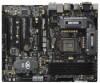
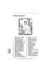
... CODEC HD_AUDIO1 1 HDMI_SPDIF1 COM1 1 1 PCIE2 RoHS PCIE3 PCI Express 3.0 PCI1 Z68 Extreme4 Gen3 CMOS Battery PCIE4 XFast USB PCI2 DX10.1 Front USB 3.0 1394a FLOPPY1 PCIE5 IR1 1 FRONT_1394 1 USB6_7 1 1 CIR1 USB8_9 1 Intel Z68 SATA2_4_5 64Mb BIOS RSTBTN Dr. Debug USB10_11 1 USB3_12_13 PWRBTN PLED1 1 SPEAKER1 1 PANEL1 PLED PWRBTN... Connector (SATA2_5, Black) 41 PCI Slot (PCI1) 19 64Mb SPI Flash 42 PCI Express 2.0 x1 Slot (PCIE3, Black) 20 Intel Z68 Chipset 43 PCI Express 3.0 x16 Slot (PCIE2, Black) 21 Reset Switch (RSTBTN) 44 PCI Express 2.0 x1 Slot (PCIE1, Black) ...
... CODEC HD_AUDIO1 1 HDMI_SPDIF1 COM1 1 1 PCIE2 RoHS PCIE3 PCI Express 3.0 PCI1 Z68 Extreme4 Gen3 CMOS Battery PCIE4 XFast USB PCI2 DX10.1 Front USB 3.0 1394a FLOPPY1 PCIE5 IR1 1 FRONT_1394 1 USB6_7 1 1 CIR1 USB8_9 1 Intel Z68 SATA2_4_5 64Mb BIOS RSTBTN Dr. Debug USB10_11 1 USB3_12_13 PWRBTN PLED1 1 SPEAKER1 1 PANEL1 PLED PWRBTN... Connector (SATA2_5, Black) 41 PCI Slot (PCI1) 19 64Mb SPI Flash 42 PCI Express 2.0 x1 Slot (PCIE3, Black) 20 Intel Z68 Chipset 43 PCI Express 3.0 x16 Slot (PCIE2, Black) 21 Reset Switch (RSTBTN) 44 PCI Express 2.0 x1 Slot (PCIE1, Black) ...

User Manual
Page 37
... Jumper (CLRCMOS1) (see p.13, No. 10) Setting Default Clear CMOS Description Note: CLRCMOS1 allows you do not clear the CMOS right after you update the BIOS. After waiting for 5 seconds. The Clear CMOS Switch has the same function as the Clear CMOS jumper. 37 If no jumper cap is placed on... off the computer and unplug the power cord from the power supply. If you need to clear the CMOS when you just nish updating the BIOS, you must boot up the system rst, and then shut it down before you to clear the data in CMOS. However, please do the clear...
... Jumper (CLRCMOS1) (see p.13, No. 10) Setting Default Clear CMOS Description Note: CLRCMOS1 allows you do not clear the CMOS right after you update the BIOS. After waiting for 5 seconds. The Clear CMOS Switch has the same function as the Clear CMOS jumper. 37 If no jumper cap is placed on... off the computer and unplug the power cord from the power supply. If you need to clear the CMOS when you just nish updating the BIOS, you must boot up the system rst, and then shut it down before you to clear the data in CMOS. However, please do the clear...

User Manual
Page 80
...® installation les. If you install Windows® 7 64-bit OS, OS will be installed on a HDD Larger Than 2TB This motherboard is adopting UEFI BIOS that allows Windows® OS to be formatted by GPT (GUID Partition Table). Please make sure to install the operating system. 1. Start Windows® installation...
...® installation les. If you install Windows® 7 64-bit OS, OS will be installed on a HDD Larger Than 2TB This motherboard is adopting UEFI BIOS that allows Windows® OS to be formatted by GPT (GUID Partition Table). Please make sure to install the operating system. 1. Start Windows® installation...
Quick Installation Guide
Page 2
...Designed in Taipei AUDIO CODEC HD_AUDIO1 1 HDMI_SPDIF1 COM1 1 1 PCIE2 RoHS PCIE3 PCI Express 3.0 PCI1 Z68 Extreme4 Gen3 CMOS Battery PCIE4 XFast USB PCI2 DX10.1 Front USB 3.0 1394a FLOPPY1 PCIE5 IR1 1 FRONT_1394 1 USB6_7 1 1 CIR1 USB8_9 1 Intel Z68 SATA2_4_5 64Mb BIOS RSTBTN Dr. Debug USB10_11 1 USB3_12_13 PWRBTN PLED1 1 SPEAKER1 1 PANEL1 PLED PWRBTN 1 HDLED RESET... 46 Chassis Fan Connector (CHA_FAN3) 24 System Panel Header (PANEL1, Black) 47 Chassis Fan Connector (CHA_FAN2) 25 Chassis Speaker Header (SPEAKER 1, Black) 2 ASRock Z68 Extreme4 Gen3 Motherboard English
...Designed in Taipei AUDIO CODEC HD_AUDIO1 1 HDMI_SPDIF1 COM1 1 1 PCIE2 RoHS PCIE3 PCI Express 3.0 PCI1 Z68 Extreme4 Gen3 CMOS Battery PCIE4 XFast USB PCI2 DX10.1 Front USB 3.0 1394a FLOPPY1 PCIE5 IR1 1 FRONT_1394 1 USB6_7 1 1 CIR1 USB8_9 1 Intel Z68 SATA2_4_5 64Mb BIOS RSTBTN Dr. Debug USB10_11 1 USB3_12_13 PWRBTN PLED1 1 SPEAKER1 1 PANEL1 PLED PWRBTN 1 HDLED RESET... 46 Chassis Fan Connector (CHA_FAN3) 24 System Panel Header (PANEL1, Black) 47 Chassis Fan Connector (CHA_FAN2) 25 Chassis Speaker Header (SPEAKER 1, Black) 2 ASRock Z68 Extreme4 Gen3 Motherboard English
Quick Installation Guide
Page 5
...... 1. Because the motherboard specifications and the BIOS software might be available on ASRock website as well. ASRock website http://www.asrock.com If you for a 3.5-in , 30.5 cm x 24.4 cm) ASRock Z68 Extreme4 Gen3 Quick Installation Guide ASRock Z68 Extreme4 Gen3 Support CD 1 x Ribbon Cable for purchasing ASRock Z68 Extreme4 Gen3 motherboard, a reliable motherboard produced under ASRock's consistently stringent quality control. To get better performance...
...... 1. Because the motherboard specifications and the BIOS software might be available on ASRock website as well. ASRock website http://www.asrock.com If you for a 3.5-in , 30.5 cm x 24.4 cm) ASRock Z68 Extreme4 Gen3 Quick Installation Guide ASRock Z68 Extreme4 Gen3 Support CD 1 x Ribbon Cable for purchasing ASRock Z68 Extreme4 Gen3 motherboard, a reliable motherboard produced under ASRock's consistently stringent quality control. To get better performance...
Quick Installation Guide
Page 8
... Tuning Utility (AXTU) (see CAUTION 9) - AMI UEFI Legal BIOS with LED - 64Mb AMI BIOS - OEM and Trial; ASRock Instant Boot English 8 ASRock Z68 Extreme4 Gen3 Motherboard SLI/XFire power connector - CPU/Chassis/Power FAN connector - 24 pin ATX...GUI support - Supports jumperfree - Drivers, Utilities, AntiVirus Software (Trial Version), CyberLink MediaEspresso 6.5 Trial, ASRock Software Suite (CyberLink DVD Suite - ASRock MAGIX Multimedia Suite - USB3.0 Connector Smart Switch BIOS Feature Support CD Unique Feature - 2 x Rear USB 3.0 ports by Etron EJ168A, support USB 1.0/ ...
... Tuning Utility (AXTU) (see CAUTION 9) - AMI UEFI Legal BIOS with LED - 64Mb AMI BIOS - OEM and Trial; ASRock Instant Boot English 8 ASRock Z68 Extreme4 Gen3 Motherboard SLI/XFire power connector - CPU/Chassis/Power FAN connector - 24 pin ATX...GUI support - Supports jumperfree - Drivers, Utilities, AntiVirus Software (Trial Version), CyberLink MediaEspresso 6.5 Trial, ASRock Software Suite (CyberLink DVD Suite - ASRock MAGIX Multimedia Suite - USB3.0 Connector Smart Switch BIOS Feature Support CD Unique Feature - 2 x Rear USB 3.0 ports by Etron EJ168A, support USB 1.0/ ...

Quick Installation Guide
Page 9
... Auto-Adjust by overclocking. FCC, CE, WHQL - We are not responsible for possible damage caused by CPU Temperature) - ASRock XFast USB (see CAUTION 16) - CPU Temperature Sensing Monitor - CPU/Chassis Fan Multi-Speed Control - It should be done...product information, please visit our website: http://www.asrock.com WARNING Please realize that there is a certain risk involved with overclocking, including adjusting the setting in the BIOS, applying Untied Overclocking Technology, or using the third-party overclocking tools. English 9 ASRock Z68 Extreme4 Gen3 Motherboard
... Auto-Adjust by overclocking. FCC, CE, WHQL - We are not responsible for possible damage caused by CPU Temperature) - ASRock XFast USB (see CAUTION 16) - CPU Temperature Sensing Monitor - CPU/Chassis Fan Multi-Speed Control - It should be done...product information, please visit our website: http://www.asrock.com WARNING Please realize that there is a certain risk involved with overclocking, including adjusting the setting in the BIOS, applying Untied Overclocking Technology, or using the third-party overclocking tools. English 9 ASRock Z68 Extreme4 Gen3 Motherboard
Quick Installation Guide
Page 11
...technology, you can press key during the POST or press key to BIOS setup menu to update system BIOS without preparing an additional floppy diskette or other complicated flash utility. ASRock Instant Flash is the smart start page for IE that combines your... SmartView, a new function of Intel® HD graphics. 11 ASRock Z68 Extreme4 Gen3 Motherboard English LAN Application Prioritization: You can configure your real-time newsfeed into Standby mode (S1), Suspend to 40% faster than ever. This convenient BIOS update tool allows you - To use FAT32/16/12 fi...
...technology, you can press key during the POST or press key to BIOS setup menu to update system BIOS without preparing an additional floppy diskette or other complicated flash utility. ASRock Instant Flash is the smart start page for IE that combines your... SmartView, a new function of Intel® HD graphics. 11 ASRock Z68 Extreme4 Gen3 Motherboard English LAN Application Prioritization: You can configure your real-time newsfeed into Standby mode (S1), Suspend to 40% faster than ever. This convenient BIOS update tool allows you - To use FAT32/16/12 fi...

Quick Installation Guide
Page 32
English 32 ASRock Z68 Extreme4 Gen3 Motherboard Jumper Clear CMOS Jumper (CLRCMOS1) (see p.2, No. 10) Setting Default Clear CMOS Description Note...on CLRCMOS1 for 15 seconds, use a jumper cap to clear the CMOS when you just finish updating the BIOS, you must boot up the system first, and then shut it down before you do not clear the CMOS...when jumper cap is removed. If no jumper cap is placed on pins, the jumper is "Open". If you update the BIOS. When the jumper cap is placed on pins, the jumper is "Short". The illustration shows a 3-pin jumper whose pin1 ...
English 32 ASRock Z68 Extreme4 Gen3 Motherboard Jumper Clear CMOS Jumper (CLRCMOS1) (see p.2, No. 10) Setting Default Clear CMOS Description Note...on CLRCMOS1 for 15 seconds, use a jumper cap to clear the CMOS when you just finish updating the BIOS, you must boot up the system first, and then shut it down before you do not clear the CMOS...when jumper cap is removed. If no jumper cap is placed on pins, the jumper is "Open". If you update the BIOS. When the jumper cap is placed on pins, the jumper is "Short". The illustration shows a 3-pin jumper whose pin1 ...

Quick Installation Guide
Page 47
The BIOS Setup program is designed to display the menus. 47 ASRock Z68 Extreme4 Gen3 Motherboard English Software Support CD information This motherboard supports various Microsoft® Windows® operating systems: 7 / 7 64-bit / VistaTM / VistaTM 64-bit / XP / XP 64-.... It is enabled in the Support CD. 4. It will enhance motherboard features. If you to scroll through its test routines. For the detailed information about BIOS Setup, please refer to enter BIOS Setup after POST, please restart the system by pressing + + , or pressing the reset button on the motherboard stores...
The BIOS Setup program is designed to display the menus. 47 ASRock Z68 Extreme4 Gen3 Motherboard English Software Support CD information This motherboard supports various Microsoft® Windows® operating systems: 7 / 7 64-bit / VistaTM / VistaTM 64-bit / XP / XP 64-.... It is enabled in the Support CD. 4. It will enhance motherboard features. If you to scroll through its test routines. For the detailed information about BIOS Setup, please refer to enter BIOS Setup after POST, please restart the system by pressing + + , or pressing the reset button on the motherboard stores...

Quick Installation Guide
Page 233
2.8 3 1-2 점퍼 CMOS 초기화 (CLRCMOS1, 3 2 10 세팅 CMOS 삭제 참고 : CLRCMOS1 CMOS 15 CLRCMOS1 의 핀 2 와 핀 3 을 5 BIOS CMOS BIOS CMOS CMOS CMOS 1394 GUID, MAC Clear CMOS Switch는 Clear CMOS 2.9 콘넥터 FDD 콘넥터 (33 핀 FLOPPY1) (2 34 그림 1 번 핀에 1 한국어 233 ASRock Z68 Extreme4 Gen3 Motherboard
2.8 3 1-2 점퍼 CMOS 초기화 (CLRCMOS1, 3 2 10 세팅 CMOS 삭제 참고 : CLRCMOS1 CMOS 15 CLRCMOS1 의 핀 2 와 핀 3 을 5 BIOS CMOS BIOS CMOS CMOS CMOS 1394 GUID, MAC Clear CMOS Switch는 Clear CMOS 2.9 콘넥터 FDD 콘넥터 (33 핀 FLOPPY1) (2 34 그림 1 번 핀에 1 한국어 233 ASRock Z68 Extreme4 Gen3 Motherboard

Quick Installation Guide
Page 260
2.8 1-2 CMOS CLRCMOS1 10 参照) 設定 説明 CMOS の消去 注 : CLRCMOS1 CMOS 15 CLRCMOS1 のピン 2 とピン 3 を 5 BIOS CMOS BIOS CMOS CMOS 1394 GUID と MAC CMOS クリアCMOS CMOS 日本語 260 ASRock Z68 Extreme4 Gen3 Motherboard
2.8 1-2 CMOS CLRCMOS1 10 参照) 設定 説明 CMOS の消去 注 : CLRCMOS1 CMOS 15 CLRCMOS1 のピン 2 とピン 3 を 5 BIOS CMOS BIOS CMOS CMOS 1394 GUID と MAC CMOS クリアCMOS CMOS 日本語 260 ASRock Z68 Extreme4 Gen3 Motherboard

Quick Installation Guide
Page 271
...; Z68 Extreme4 Gen3 主板 (ATX 規格 : 12.0 英吋 X 9.6 英吋 , 30.5 厘米 X 24.4 厘米 ) 華擎 Z68 Extreme4 Gen3 Z68 Extreme4 Gen3 3.5 Serial ATA(SATA Serial ATA(SATA 3.5mm I/O USB 3.0 USB 3.0 SLI_Bridge_2S 橋接卡 ASRock 為了在 Windows® 7 / 7 64-bit / VistaTM / VistaTM 64-bit BIOS中將Storage Configuration AHCI BIOS User Manual 271 ASRock Z68 Extreme4 Gen3...
...; Z68 Extreme4 Gen3 主板 (ATX 規格 : 12.0 英吋 X 9.6 英吋 , 30.5 厘米 X 24.4 厘米 ) 華擎 Z68 Extreme4 Gen3 Z68 Extreme4 Gen3 3.5 Serial ATA(SATA Serial ATA(SATA 3.5mm I/O USB 3.0 USB 3.0 SLI_Bridge_2S 橋接卡 ASRock 為了在 Windows® 7 / 7 64-bit / VistaTM / VistaTM 64-bit BIOS中將Storage Configuration AHCI BIOS User Manual 271 ASRock Z68 Extreme4 Gen3...

Quick Installation Guide
Page 275
... - FCC, CE, WHQL - 支持 ErP/EuP ErP/EuP 20) http://www.asrock.com BIOS 警告! 1、 關于"Hyper-Threading Technology CD User Manual 66 BIOS 8 2 280 3、 DDR3 K- 系列 CPU 支持 DDR3 超頻...;元 /VistaTM 支持 HBR。 8 2 聲道、4 聲道、6 8 3 9、 ASRock Extreme Tuning Utility (AXTU O C DNA 和 IES。在 Hardware Monitor ASRock Z68 Extreme4 Gen3 Motherboard 275 簡體中文
... - FCC, CE, WHQL - 支持 ErP/EuP ErP/EuP 20) http://www.asrock.com BIOS 警告! 1、 關于"Hyper-Threading Technology CD User Manual 66 BIOS 8 2 280 3、 DDR3 K- 系列 CPU 支持 DDR3 超頻...;元 /VistaTM 支持 HBR。 8 2 聲道、4 聲道、6 8 3 9、 ASRock Extreme Tuning Utility (AXTU O C DNA 和 IES。在 Hardware Monitor ASRock Z68 Extreme4 Gen3 Motherboard 275 簡體中文

Quick Installation Guide
Page 295
BIOS 信息 Flash Memory 存儲了 BIOS POST F2> 或 < D e l B I O S P O S T P O S T B I O S Ctrl>++ 3.
BIOS 信息 Flash Memory 存儲了 BIOS POST F2> 或 < D e l B I O S P O S T P O S T B I O S Ctrl>++ 3.


