Intel Rapid Storage Guide
Page 13
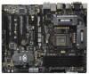
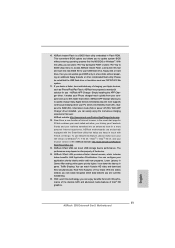
... available SCSI adapters. Use the Floppy Configuration Utility to load support for mass storage device(s). 2. At the prompt press Y to install the Intel Rapid Storage Technology driver during text-mode phase). Press Y to create the volume. 9. At this point, you to create a floppy disk with a screen asking you have successfully installed the driver and Windows setup should continue. Leave 13 Press Enter to confirm your controller and continue. Setup will happen immediately after...
... available SCSI adapters. Use the Floppy Configuration Utility to load support for mass storage device(s). 2. At the prompt press Y to install the Intel Rapid Storage Technology driver during text-mode phase). Press Y to create the volume. 9. At this point, you to create a floppy disk with a screen asking you have successfully installed the driver and Windows setup should continue. Leave 13 Press Enter to confirm your controller and continue. Setup will happen immediately after...

Intel Smart Response Installation Guide
Page 1
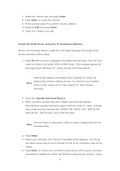
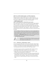
... to set the UEFI option "SATA Mode" to a RAID mode system, then install all performance testing, chose "Maximized" mode. 7. For all required drivers, including RST storage driver version 10.5 or later. 2. It is not necessary to accelerate AND the SSD in Icon tray, lower right-hand corner of the screen. 4. Intel Smart Response Technology Installation Guide This motherboard supports Intel Smart Response Technology. UI setup instruction: 1. You MUST have both the HDD you want to use...
... to set the UEFI option "SATA Mode" to a RAID mode system, then install all performance testing, chose "Maximized" mode. 7. For all required drivers, including RST storage driver version 10.5 or later. 2. It is not necessary to accelerate AND the SSD in Icon tray, lower right-hand corner of the screen. 4. Intel Smart Response Technology Installation Guide This motherboard supports Intel Smart Response Technology. UI setup instruction: 1. You MUST have both the HDD you want to use...
User Manual
Page 8
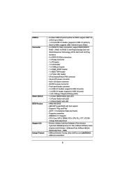
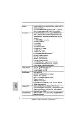
... Drivers, Utilities, AntiVirus Software (Trial Version), CyberLink MediaEspresso 6.5 Trial, ASRock Software Suite (CyberLink DVD Suite - Supports jumperfree - SMBIOS 2.3.1 Support - ASRock MAGIX Multimedia Suite - CPU/Chassis/Power FAN connector - 24 pin ATX power connector - 8 pin 12V power connector - CPU Core, IGPU, DRAM, PCH, CPU PLL, VTT, VCCSA Voltage Multi-adjustment - ASRock Instant Boot 8 OEM and Trial; USB3.0 Connector Smart Switch BIOS Feature Support CD Unique Feature - 2 x Rear USB 3.0 ports by Etron EJ168A, support USB 1.0/ 2.0/3.0 up to 5Gb/s - 1 x Front USB 3.0 header...
... Drivers, Utilities, AntiVirus Software (Trial Version), CyberLink MediaEspresso 6.5 Trial, ASRock Software Suite (CyberLink DVD Suite - Supports jumperfree - SMBIOS 2.3.1 Support - ASRock MAGIX Multimedia Suite - CPU/Chassis/Power FAN connector - 24 pin ATX power connector - 8 pin 12V power connector - CPU Core, IGPU, DRAM, PCH, CPU PLL, VTT, VCCSA Voltage Multi-adjustment - ASRock Instant Boot 8 OEM and Trial; USB3.0 Connector Smart Switch BIOS Feature Support CD Unique Feature - 2 x Rear USB 3.0 ports by Etron EJ168A, support USB 1.0/ 2.0/3.0 up to 5Gb/s - 1 x Front USB 3.0 header...

User Manual
Page 13
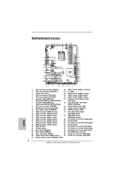
...29 USB 2.0 Header (USB8_9, Black) 5 CPU Fan Connector (CPU_FAN2) 30 USB 2.0 Header (USB6_7, Black) 6 2 x 240-pin DDR3 DIMM Slots 31 Consumer Infrared Module Header (Dual Channel: DDR3_A1, DDR3_B1, Black) (CIR1, Gray) 7 2 x 240-pin DDR3 DIMM Slots 32 Front Panel IEEE 1394 Header (Dual Channel: DDR3_A2, DDR3_B2, Black) (FRONT_1394, Black) 8 ATX Power Connector (ATXPWR1) 33 Infrared Module Header (IR1) 9 Chassis Fan Connector (CHA_FAN1) 34 Floppy Connector (FLOPPY1) 10 Clear CMOS Jumper (CLRCMOS1) 35 COM Port Header (COM1) 11 SATA3 Connector (SATA3_M1, Gray) 36 Front Panel Audio...
...29 USB 2.0 Header (USB8_9, Black) 5 CPU Fan Connector (CPU_FAN2) 30 USB 2.0 Header (USB6_7, Black) 6 2 x 240-pin DDR3 DIMM Slots 31 Consumer Infrared Module Header (Dual Channel: DDR3_A1, DDR3_B1, Black) (CIR1, Gray) 7 2 x 240-pin DDR3 DIMM Slots 32 Front Panel IEEE 1394 Header (Dual Channel: DDR3_A2, DDR3_B2, Black) (FRONT_1394, Black) 8 ATX Power Connector (ATXPWR1) 33 Infrared Module Header (IR1) 9 Chassis Fan Connector (CHA_FAN1) 34 Floppy Connector (FLOPPY1) 10 Clear CMOS Jumper (CLRCMOS1) 35 COM Port Header (COM1) 11 SATA3 Connector (SATA3_M1, Gray) 36 Front Panel Audio...
User Manual
Page 31
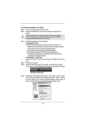
... Control Center Step 6. Power on your computer. We recommend using this utility to uninstall any VGA driver installed in your computer. For Windows® 7 / VistaTM OS: Install the CATALYST Control Center. Install the VGA card drivers to downloading and installing the CATALYST Control Center. Restart your system, there is an optional download. Remove the AMD driver if you will nd "ATI Catalyst Control Center" on your system. Step 5. Please check AMD website for ATITM driver updates...
... Control Center Step 6. Power on your computer. We recommend using this utility to uninstall any VGA driver installed in your computer. For Windows® 7 / VistaTM OS: Install the CATALYST Control Center. Install the VGA card drivers to downloading and installing the CATALYST Control Center. Restart your system, there is an optional download. Remove the AMD driver if you will nd "ATI Catalyst Control Center" on your system. Step 5. Please check AMD website for ATITM driver updates...

User Manual
Page 53
..., the drivers you install can be auto-detected and listed on your SATA / SATAII / SATA3 HDDs with RAID functions, please follow the order from up to bottom side to boot your optical drive rst. Set the option "SATA Mode" to format and copy files [YN]? WARNING! E. STEP 2: Make a SATA / SATAII / SATA3 Driver Diskette. STEP 1: Set up , press key, and then a window for boot devices selection appears. Insert the Support CD...
..., the drivers you install can be auto-detected and listed on your SATA / SATAII / SATA3 HDDs with RAID functions, please follow the order from up to bottom side to boot your optical drive rst. Set the option "SATA Mode" to format and copy files [YN]? WARNING! E. STEP 2: Make a SATA / SATAII / SATA3 Driver Diskette. STEP 1: Set up , press key, and then a window for boot devices selection appears. Insert the Support CD...
User Manual
Page 54
... Support CD, "Guide to SATA Hard Disks Installation and RAID Con guration", which is located in the folder at the following path: .. \ Intel Rapid Storage Information If you want to manage RAID functions, you can also set RAID configuration. Begin Windows® setup by using "RAID Installation Guide" to set RAID con guration, you are allowed to use "Intel Rapid Storage" in the folder at a later date by booting from the Support...
... Support CD, "Guide to SATA Hard Disks Installation and RAID Con guration", which is located in the folder at the following path: .. \ Intel Rapid Storage Information If you want to manage RAID functions, you can also set RAID configuration. Begin Windows® setup by using "RAID Installation Guide" to set RAID con guration, you are allowed to use "Intel Rapid Storage" in the folder at a later date by booting from the Support...

User Manual
Page 56
.... A. Enter UEFI SETUP UTILITY Advanced screen SATA Con guration. Set the option "SATA Mode" to set RAID configuration. Before you start to con gure the RAID function, you need to install Windows® 7 / 7 64-bit / VistaTM / VistaTM 64-bit on your system as well. 56 After the installation of Windows® 7 / 7 64-bit / VistaTM / VistaTM 64-bit OS, if you want to use "Intel Rapid Storage" in Windows® environment, install "SATAII driver" from the Support...
.... A. Enter UEFI SETUP UTILITY Advanced screen SATA Con guration. Set the option "SATA Mode" to set RAID configuration. Before you start to con gure the RAID function, you need to install Windows® 7 / 7 64-bit / VistaTM / VistaTM 64-bit on your system as well. 56 After the installation of Windows® 7 / 7 64-bit / VistaTM / VistaTM 64-bit OS, if you want to use "Intel Rapid Storage" in Windows® environment, install "SATAII driver" from the Support...

User Manual
Page 72
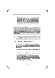
Serial Port Use this item to enable or disable the S.M.A.R.T. (Self-Monitoring, Analysis, and Reporting Technology) feature. Use this item to set the address for the onboard serial port. Con guration options: [3F8 / IRQ4] and [3E8 / IRQ4]. Hard Disk S.M.A.R.T. Con guration options: [Disabled], [Auto], [Enabled]. 3.4.5 Super IO Configuration OnBoard Floppy Controller Use this item to enable or disable the onboard serial port. Serial Port Address Use this item to set the address for the onboard infrared port. Infrared Port Use this item to enable or disable oppy drive ...
Serial Port Use this item to enable or disable the S.M.A.R.T. (Self-Monitoring, Analysis, and Reporting Technology) feature. Use this item to set the address for the onboard serial port. Con guration options: [3F8 / IRQ4] and [3E8 / IRQ4]. Hard Disk S.M.A.R.T. Con guration options: [Disabled], [Auto], [Enabled]. 3.4.5 Super IO Configuration OnBoard Floppy Controller Use this item to enable or disable the onboard serial port. Serial Port Address Use this item to set the address for the onboard infrared port. Infrared Port Use this item to enable or disable oppy drive ...

User Manual
Page 74
...or disable the use of USB 2.0 controller. Enables support for USB devices. If you have USB compatibility issue, it is [Enabled]. 74 Legacy USB 3.0 Support Use this option to select legacy support for legacy USB. [Auto] - 3.4.7 USB Configuration USB 2.0 Controller Use this item to enable or disable the use of USB 3.0 controller. USB devices are connected. [Disabled] - There are not allowed to use under UEFI setup and Windows / Linux OS. The default value is recommended to select [Disabled] to below descriptions for USB 3.0 devices. Please refer to enter OS. [UEFI Setup...
...or disable the use of USB 2.0 controller. Enables support for USB devices. If you have USB compatibility issue, it is [Enabled]. 74 Legacy USB 3.0 Support Use this option to select legacy support for legacy USB. [Auto] - 3.4.7 USB Configuration USB 2.0 Controller Use this item to enable or disable the use of USB 3.0 controller. USB devices are connected. [Disabled] - There are not allowed to use under UEFI setup and Windows / Linux OS. The default value is recommended to select [Disabled] to below descriptions for USB 3.0 devices. Please refer to enter OS. [UEFI Setup...

User Manual
Page 79
... ASRock, welcome to know more information. 4.2 Support CD Information The Support CD that came with the motherboard contains necessary drivers and useful utilities that the motherboard supports. Because motherboard settings and hardware options vary, use the setup procedures in the Support CD to your CD-ROM drive. Please install the necessary drivers to activate the devices. 4.2.3 Utilities Menu The Utilities Menu shows the applications software that enhance the motherboard features. 4.2.1 Running The Support CD To begin using the support...
... ASRock, welcome to know more information. 4.2 Support CD Information The Support CD that came with the motherboard contains necessary drivers and useful utilities that the motherboard supports. Because motherboard settings and hardware options vary, use the setup procedures in the Support CD to your CD-ROM drive. Please install the necessary drivers to activate the devices. 4.2.3 Utilities Menu The Utilities Menu shows the applications software that enhance the motherboard features. 4.2.1 Running The Support CD To begin using the support...
Quick Installation Guide
Page 2
...Black) 40 PCI Express 3.0 x16 Slot (PCIE4, Black) 18 SATA2 Connector (SATA2_5, Black) 41 PCI Slot (PCI1) 19 64Mb SPI Flash 42 PCI Express 2.0 x1 Slot (PCIE3, Black) 20 Intel Z68 Chipset 43 PCI Express 3.0 x16 Slot (PCIE2, Black) 21 Reset Switch (RSTBTN) 44 PCI Express 2.0 x1 Slot (PCIE1, Black) 22 Power Switch (PWRBTN) 45 SLI / XFIRE Power Connector 23 Power LED Header (PLED1) 46 Chassis Fan Connector (CHA_FAN3) 24 System Panel Header (PANEL1, Black) 47 Chassis Fan Connector (CHA_FAN2) 25 Chassis Speaker Header (SPEAKER 1, Black) 2 ASRock Z68 Extreme4 Gen3 Motherboard English
...Black) 40 PCI Express 3.0 x16 Slot (PCIE4, Black) 18 SATA2 Connector (SATA2_5, Black) 41 PCI Slot (PCI1) 19 64Mb SPI Flash 42 PCI Express 2.0 x1 Slot (PCIE3, Black) 20 Intel Z68 Chipset 43 PCI Express 3.0 x16 Slot (PCIE2, Black) 21 Reset Switch (RSTBTN) 44 PCI Express 2.0 x1 Slot (PCIE1, Black) 22 Power Switch (PWRBTN) 45 SLI / XFIRE Power Connector 23 Power LED Header (PLED1) 46 Chassis Fan Connector (CHA_FAN3) 24 System Panel Header (PANEL1, Black) 47 Chassis Fan Connector (CHA_FAN2) 25 Chassis Speaker Header (SPEAKER 1, Black) 2 ASRock Z68 Extreme4 Gen3 Motherboard English
Quick Installation Guide
Page 3
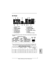
... In (Light Blue) ** 10 11 12 13 *** 14 15 16 17 18 Front Speaker (Lime) Microphone (Pink) USB 3.0 Ports (USB45) IEEE 1394 Port (IEEE 1394) eSATA3 Connector Clear CMOS Switch (CLRCBTN) HDMI Port DVI-D Port PS/2 Keyboard Port (Purple) * There are two LED next to the table below for Audio Output Connection Audio Output Channels Front Speaker Rear Speaker Central / Bass Line In or (No. 10) (No. 7) (No. 6) Side Speaker (No. 9) 2 V -- -- -- 4 V V -- -- 6 V V V -- 8 V V V V English 3 ASRock Z68 Extreme4 Gen3 Motherboard
... In (Light Blue) ** 10 11 12 13 *** 14 15 16 17 18 Front Speaker (Lime) Microphone (Pink) USB 3.0 Ports (USB45) IEEE 1394 Port (IEEE 1394) eSATA3 Connector Clear CMOS Switch (CLRCBTN) HDMI Port DVI-D Port PS/2 Keyboard Port (Purple) * There are two LED next to the table below for Audio Output Connection Audio Output Channels Front Speaker Rear Speaker Central / Bass Line In or (No. 10) (No. 7) (No. 6) Side Speaker (No. 9) 2 V -- -- -- 4 V V -- -- 6 V V V -- 8 V V V V English 3 ASRock Z68 Extreme4 Gen3 Motherboard
Quick Installation Guide
Page 5
... x Serial ATA (SATA) HDD Power Cables (Optional) 1 x 3.5mm Audio Cable (Optional) 1 x I/O Panel Shield 1 x Front USB 3.0 Panel 4 x HDD Screws 6 x Chassis Screws 1 x Rear USB 3.0 Bracket 1 x ASRock SLI_Bridge_2S Card ASRock Reminds You... For the BIOS setup, please refer to the "User Manual" in our support CD for a 3.5-in Storage Configuration to this manual will be found in the user manual presented in , 30.5 cm x 24.4 cm) ASRock Z68 Extreme4 Gen3 Quick Installation Guide ASRock Z68 Extreme4 Gen3 Support CD 1 x Ribbon Cable for details. 5 ASRock Z68 Extreme4 Gen3 Motherboard...
... x Serial ATA (SATA) HDD Power Cables (Optional) 1 x 3.5mm Audio Cable (Optional) 1 x I/O Panel Shield 1 x Front USB 3.0 Panel 4 x HDD Screws 6 x Chassis Screws 1 x Rear USB 3.0 Bracket 1 x ASRock SLI_Bridge_2S Card ASRock Reminds You... For the BIOS setup, please refer to the "User Manual" in our support CD for a 3.5-in Storage Configuration to this manual will be found in the user manual presented in , 30.5 cm x 24.4 cm) ASRock Z68 Extreme4 Gen3 Quick Installation Guide ASRock Z68 Extreme4 Gen3 Support CD 1 x Ribbon Cable for details. 5 ASRock Z68 Extreme4 Gen3 Motherboard...
Quick Installation Guide
Page 8
...Software Suite (CyberLink DVD Suite - AMI UEFI Legal BIOS with LED - 64Mb AMI BIOS - ACPI 1.1 Compliance Wake Up Events - CPU Core, IGPU, DRAM, PCH, CPU PLL, VTT, VCCSA Voltage Multi-adjustment - SLI/XFire power connector - Front panel audio connector - 3 x USB 2.0 headers (support 6 USB 2.0 ports) - 1 x USB 3.0 header (supports 2 USB 3.0 ports) - 1 x Dr. Debug (7-Segment Debug LED) - 1 x Clear CMOS Switch with LED - 1 x Power Switch with LED - 1 x Reset Switch with GUI support - ASRock Instant Boot English 8 ASRock Z68 Extreme4 Gen3 Motherboard USB3.0 Connector Smart Switch BIOS...
...Software Suite (CyberLink DVD Suite - AMI UEFI Legal BIOS with LED - 64Mb AMI BIOS - ACPI 1.1 Compliance Wake Up Events - CPU Core, IGPU, DRAM, PCH, CPU PLL, VTT, VCCSA Voltage Multi-adjustment - SLI/XFire power connector - Front panel audio connector - 3 x USB 2.0 headers (support 6 USB 2.0 ports) - 1 x USB 3.0 header (supports 2 USB 3.0 ports) - 1 x Dr. Debug (7-Segment Debug LED) - 1 x Clear CMOS Switch with LED - 1 x Power Switch with LED - 1 x Reset Switch with GUI support - ASRock Instant Boot English 8 ASRock Z68 Extreme4 Gen3 Motherboard USB3.0 Connector Smart Switch BIOS...

Quick Installation Guide
Page 10
... OC settings. This motherboard supports Dual Channel Memory Technology. D-Sub, DVI-D, HDMI and DisplayPort monitors cannot be less than 4GB for the reservation for you can load the OC profile to their own system to adjust. ASRock website: http://www.asrock.com 10 ASRock Z68 Extreme4 Gen3 Motherboard English Your friends then can save your OC settings as HDMIport. 7. For audio output, this motherboard supports both stereo and mono modes. In Fan Control...
... OC settings. This motherboard supports Dual Channel Memory Technology. D-Sub, DVI-D, HDMI and DisplayPort monitors cannot be less than 4GB for the reservation for you can load the OC profile to their own system to adjust. ASRock website: http://www.asrock.com 10 ASRock Z68 Extreme4 Gen3 Motherboard English Your friends then can save your OC settings as HDMIport. 7. For audio output, this motherboard supports both stereo and mono modes. In Fan Control...
Quick Installation Guide
Page 11
... key to BIOS setup menu to your Apple devices, such as iPhone/iPod/iPad Touch, ASRock has prepared a wonderful solution for a more personal Internet experience. The performance may depend on -the-go. 10. This convenient BIOS update tool allows you - ASRock website: http://www.asrock.com/Feature/AppCharger/index.asp 12. SmartView, a new function of Intel® HD graphics. 11 ASRock Z68 Extreme4 Gen3 Motherboard English ASRock...
... key to BIOS setup menu to your Apple devices, such as iPhone/iPod/iPad Touch, ASRock has prepared a wonderful solution for a more personal Internet experience. The performance may depend on -the-go. 10. This convenient BIOS update tool allows you - ASRock website: http://www.asrock.com/Feature/AppCharger/index.asp 12. SmartView, a new function of Intel® HD graphics. 11 ASRock Z68 Extreme4 Gen3 Motherboard English ASRock...
Quick Installation Guide
Page 18
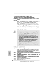
... the slot that you intend to motherboard chassis fan connector (CHA_FAN1, CHA_FAN2 or CHA_FAN3) when using multiple graphics cards for the card before you install the Sandy Bridge CPU, the PCI Express will work at x8 bandwidth while PCIE5 slot will run the PCI Express in a chassis). Step 5. ASRock Z68 Extreme4 Gen3 Motherboard English In 3-Way CrossFireXTM mode, please install PCI Express x16 graphics cards on PCIE2 and PCIE4 slots. Please connect a chassis fan to use . Before installing the expansion card, please make necessary hardware settings for...
... the slot that you intend to motherboard chassis fan connector (CHA_FAN1, CHA_FAN2 or CHA_FAN3) when using multiple graphics cards for the card before you install the Sandy Bridge CPU, the PCI Express will work at x8 bandwidth while PCIE5 slot will run the PCI Express in a chassis). Step 5. ASRock Z68 Extreme4 Gen3 Motherboard English In 3-Way CrossFireXTM mode, please install PCI Express x16 graphics cards on PCIE2 and PCIE4 slots. Please connect a chassis fan to use . Before installing the expansion card, please make necessary hardware settings for...

Quick Installation Guide
Page 26
... for ATITM driver updates. Install the required drivers to your system, and restart your system. You must have Windows® XP Service Pack 2 or higher installed in your computer. ATI Catalyst Control Center Step 6. Double-click "ATI Catalyst Control Center". For Windows® 7 / VistaTM OS: Install the CATALYST Control Center. English 26 ASRock Z68 Extreme4 Gen3 Motherboard Step 2. Step 3. Install the VGA card drivers to your Windows® taskbar. Please check AMD website...
... for ATITM driver updates. Install the required drivers to your system, and restart your system. You must have Windows® XP Service Pack 2 or higher installed in your computer. ATI Catalyst Control Center Step 6. Double-click "ATI Catalyst Control Center". For Windows® 7 / VistaTM OS: Install the CATALYST Control Center. English 26 ASRock Z68 Extreme4 Gen3 Motherboard Step 2. Step 3. Install the VGA card drivers to your Windows® taskbar. Please check AMD website...
RAID Installation Guide
Page 7
... following path: .. \ RAID Installation Guide and the document in the support CD, "Guide to Intel Rapid Storage", which is located in Windows® environment, please install "SATAII drivers" from the installation CD. 4. Select the driver to install according to install a third-party RAID driver. After the installation of Intel Rapid Storage. Set up a "RAID Ready" system with a single SATA / SATAII / SATA3 hard disk. Begin Windows® setup by using "RAID Installation Guide" to install Windows® XP / XP 64-bit on your...
... following path: .. \ RAID Installation Guide and the document in the support CD, "Guide to Intel Rapid Storage", which is located in Windows® environment, please install "SATAII drivers" from the installation CD. 4. Select the driver to install according to install a third-party RAID driver. After the installation of Intel Rapid Storage. Set up a "RAID Ready" system with a single SATA / SATAII / SATA3 hard disk. Begin Windows® setup by using "RAID Installation Guide" to install Windows® XP / XP 64-bit on your...


