
User Manual
Page 7
... port) - 2 x USB 3.0 ports by ASMedia ASM1042, support USB 1.0/2.0/3.0 up to -Use USB 3.0 Ports - 1 x RJ-45 LAN Port with LED (ACT/LINK LED and SPEED LED) - 1 x Clear CMOS Switch with LED - Supports Wake-On-LAN - Realtek RTL8111E - Audio LAN Rear Panel I /O Panel - 1 x PS/2 Keyboard Port - 1 x D-Sub Port - 1 x DVI-D Port - 1 x HDMI Port - 1 x Optical SPDIF...
... port) - 2 x USB 3.0 ports by ASMedia ASM1042, support USB 1.0/2.0/3.0 up to -Use USB 3.0 Ports - 1 x RJ-45 LAN Port with LED (ACT/LINK LED and SPEED LED) - 1 x Clear CMOS Switch with LED - Supports Wake-On-LAN - Realtek RTL8111E - Audio LAN Rear Panel I /O Panel - 1 x PS/2 Keyboard Port - 1 x D-Sub Port - 1 x DVI-D Port - 1 x HDMI Port - 1 x Optical SPDIF...

User Manual
Page 8
... header - 1 x HDMI_SPDIF header - 1 x Power LED header - SMBIOS 2.3.1 Support - ASRock MAGIX Multimedia Suite - OEM) - ASRock SmartView (see CAUTION 13) - ASRock XFast USB (see CAUTION 12) - ASRock On/Off Play Technology (see CAUTION 14) - Front panel audio connector - 4 x USB 2.0 headers (support 8 USB 2.0 ports) - 1 x Dr. Debug (7-Segment Debug LED) - 1 x Clear CMOS Switch with LED - 1 x Power Switch with LED - 1 x Reset...
... header - 1 x HDMI_SPDIF header - 1 x Power LED header - SMBIOS 2.3.1 Support - ASRock MAGIX Multimedia Suite - OEM) - ASRock SmartView (see CAUTION 13) - ASRock XFast USB (see CAUTION 12) - ASRock On/Off Play Technology (see CAUTION 14) - Front panel audio connector - 4 x USB 2.0 headers (support 8 USB 2.0 ports) - 1 x Dr. Debug (7-Segment Debug LED) - 1 x Clear CMOS Switch with LED - 1 x Power Switch with LED - 1 x Reset...

User Manual
Page 13
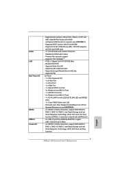
... CHA_FAN2 LAN PHY HDMI 1.4a 40 PCIE1 XFast USB AUDIO CODEC PCI Express 3.0 Z68 Extreme3 Gen3 39 PCIE2 Intel 10 SATA2_4_5 SATA2_2_3 SATA3_0_1 CMOS 38 PCIE3 Battery Super I/O 37 PCI1 SATA3 6Gb/s Z68 11 12 13 14 15 Designed in Taipei 36 35 RoHS HD_AUDIO1 1 HDMI_SPDIF1 1...Fan Connector (PWR_FAN1) 24 Dr. Debug 4 CPU Fan Connector (CPU_FAN1) 25 USB 2.0 Header (USB12_13, Black) 5 2 x 240-pin DDR3 DIMM Slots 26 Clear CMOS Jumper (CLRCMOS1) (Dual Channel: DDR3_A1, DDR3_B1, Black) 27 USB 2.0 Header (USB10_11, Black) 6 2 x 240-pin DDR3 DIMM Slots 28 USB 2.0 Header ...
... CHA_FAN2 LAN PHY HDMI 1.4a 40 PCIE1 XFast USB AUDIO CODEC PCI Express 3.0 Z68 Extreme3 Gen3 39 PCIE2 Intel 10 SATA2_4_5 SATA2_2_3 SATA3_0_1 CMOS 38 PCIE3 Battery Super I/O 37 PCI1 SATA3 6Gb/s Z68 11 12 13 14 15 Designed in Taipei 36 35 RoHS HD_AUDIO1 1 HDMI_SPDIF1 1...Fan Connector (PWR_FAN1) 24 Dr. Debug 4 CPU Fan Connector (CPU_FAN1) 25 USB 2.0 Header (USB12_13, Black) 5 2 x 240-pin DDR3 DIMM Slots 26 Clear CMOS Jumper (CLRCMOS1) (Dual Channel: DDR3_A1, DDR3_B1, Black) 27 USB 2.0 Header (USB10_11, Black) 6 2 x 240-pin DDR3 DIMM Slots 28 USB 2.0 Header ...

User Manual
Page 14
... 8 Line In (Light Blue) 14 13 12 11 ** 9 10 11 *** 12 13 14 15 16 Front Speaker (Lime) Microphone (Pink) USB 3.0 Ports (USB45) eSATA3 Connector Clear CMOS Switch (CLRCBTN) HDMI Port (HDMI1) DVI-D Port (DVI1) PS/2 Keyboard Port (Purple) * There are two LED next to the table below for connection details in...
... 8 Line In (Light Blue) 14 13 12 11 ** 9 10 11 *** 12 13 14 15 16 Front Speaker (Lime) Microphone (Pink) USB 3.0 Ports (USB45) eSATA3 Connector Clear CMOS Switch (CLRCBTN) HDMI Port (HDMI1) DVI-D Port (DVI1) PS/2 Keyboard Port (Purple) * There are two LED next to the table below for connection details in...

User Manual
Page 36
...are setup. If you need to clear the CMOS when you just finish updating the BIOS, you must boot up the system first, and then shut it down before you do not clear the CMOS right after you to clear the data in CMOS. Jumper Clear CMOS Jumper (CLRCMOS1) (see p.13..., No. 26) Setting Default Clear CMOS Description Note: CLRCMOS1 allows you update the BIOS. However, please do the clear-CMOS action. Please be noted that the password, ...
...are setup. If you need to clear the CMOS when you just finish updating the BIOS, you must boot up the system first, and then shut it down before you do not clear the CMOS right after you to clear the data in CMOS. Jumper Clear CMOS Jumper (CLRCMOS1) (see p.13..., No. 26) Setting Default Clear CMOS Description Note: CLRCMOS1 allows you update the BIOS. However, please do the clear-CMOS action. Please be noted that the password, ...

User Manual
Page 42
2.13 Smart Switches The motherboard has three smart switches: power switch, reset switch and clear CMOS switch, allowing users to quickly turn on /off the system. Clear CMOS Switch (CLRCBTN) (see p.14 No. 13) Clear CMOS Switch is a smart switch, allowing users to quickly reset the system. Reset Switch (RSTBTN) (see p.13 No. 19) Power Switch is a smart switch, allowing users to quickly clear the CMOS values. 42 Power Switch (PWRBTN) (see p.13 No. 17) Reset Switch is a smart switch, allowing users to quickly turn on /off or reset the sytem clear the CMOS values.
2.13 Smart Switches The motherboard has three smart switches: power switch, reset switch and clear CMOS switch, allowing users to quickly turn on /off the system. Clear CMOS Switch (CLRCBTN) (see p.14 No. 13) Clear CMOS Switch is a smart switch, allowing users to quickly reset the system. Reset Switch (RSTBTN) (see p.13 No. 19) Power Switch is a smart switch, allowing users to quickly clear the CMOS values. 42 Power Switch (PWRBTN) (see p.13 No. 17) Reset Switch is a smart switch, allowing users to quickly turn on /off or reset the sytem clear the CMOS values.

Quick Installation Guide
Page 2
... Fan Connector (CHA_FAN1) 3 Power Fan Connector (PWR_FAN1) 24 Dr. Debug 4 CPU Fan Connector (CPU_FAN1) 25 USB 2.0 Header (USB12_13, Black) 5 2 x 240-pin DDR3 DIMM Slots 26 Clear CMOS Jumper (CLRCMOS1) (Dual Channel: DDR3_A1, DDR3_B1, Black) 27 USB 2.0 Header (USB10_11, Black) 6 2 x 240-pin DDR3 DIMM Slots 28 USB 2.0 Header (USB8_9, Black) (Dual Channel: DDR3_A2..., Black) 20 System Panel Header (PANEL1, Black) 40 PCI Express 2.0 x1 Slot (PCIE1, Black) 21 Chassis Speaker Header (SPEAKER 1, Black) 41 Chassis Fan Connector (CHA_FAN3) 2 ASRock Z68 Extreme3 Gen3 Motherboard English
... Fan Connector (CHA_FAN1) 3 Power Fan Connector (PWR_FAN1) 24 Dr. Debug 4 CPU Fan Connector (CPU_FAN1) 25 USB 2.0 Header (USB12_13, Black) 5 2 x 240-pin DDR3 DIMM Slots 26 Clear CMOS Jumper (CLRCMOS1) (Dual Channel: DDR3_A1, DDR3_B1, Black) 27 USB 2.0 Header (USB10_11, Black) 6 2 x 240-pin DDR3 DIMM Slots 28 USB 2.0 Header (USB8_9, Black) (Dual Channel: DDR3_A2..., Black) 20 System Panel Header (PANEL1, Black) 40 PCI Express 2.0 x1 Slot (PCIE1, Black) 21 Chassis Speaker Header (SPEAKER 1, Black) 41 Chassis Fan Connector (CHA_FAN3) 2 ASRock Z68 Extreme3 Gen3 Motherboard English
Quick Installation Guide
Page 3
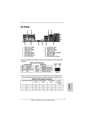
...Rear Speaker Central / Bass Line In or (No. 9) (No. 6) (No. 5) Side Speaker (No. 8) 2 V -- -- -- 4 V V -- -- 6 V V V -- 8 V V V V English 3 ASRock Z68 Extreme3 Gen3 Motherboard I/O Panel 1 2 34 5 8 6 9 7 10 16 15 1 USB 2.0 Ports (USB01) 2 D-Sub Port (VGA1) 3 USB 2.0 Ports (USB23) * 4 LAN RJ-45 Port 5 Central / Bass (Orange) ...11 ** 9 10 11 *** 12 13 14 15 16 Front Speaker (Lime) Microphone (Pink) USB 3.0 Ports (USB45) eSATA3 Connector Clear CMOS Switch (CLRCBTN) HDMI Port (HDMI1) DVI-D Port (DVI1) PS/2 Keyboard Port (Purple) * There are two LED next to ...
...Rear Speaker Central / Bass Line In or (No. 9) (No. 6) (No. 5) Side Speaker (No. 8) 2 V -- -- -- 4 V V -- -- 6 V V V -- 8 V V V V English 3 ASRock Z68 Extreme3 Gen3 Motherboard I/O Panel 1 2 34 5 8 6 9 7 10 16 15 1 USB 2.0 Ports (USB01) 2 D-Sub Port (VGA1) 3 USB 2.0 Ports (USB23) * 4 LAN RJ-45 Port 5 Central / Bass (Orange) ...11 ** 9 10 11 *** 12 13 14 15 16 Front Speaker (Lime) Microphone (Pink) USB 3.0 Ports (USB45) eSATA3 Connector Clear CMOS Switch (CLRCBTN) HDMI Port (HDMI1) DVI-D Port (DVI1) PS/2 Keyboard Port (Purple) * There are two LED next to ...
Quick Installation Guide
Page 7
... port) - 2 x USB 3.0 ports by ASMedia ASM1042, support USB 1.0/2.0/3.0 up to -Use USB 3.0 Ports - 1 x RJ-45 LAN Port with LED (ACT/LINK LED and SPEED LED) - 1 x Clear CMOS Switch with HDMI (Compliant HDMI monitor is shared with DVI and HDMI - Supports Full HD 1080p Blu-ray (BD) / HD-DVD playback with DVI and.../s - 4 x SATA2 3.0 Gb/s connectors, support RAID (RAID 0, RAID 1, RAID 10, RAID 5, Intel Rapid Storage and Intel Smart Response Technology), NCQ, AHCI and Hot Plug functions English 7 ASRock Z68 Extreme3 Gen3 Motherboard Supports Wake-On-LAN -
... port) - 2 x USB 3.0 ports by ASMedia ASM1042, support USB 1.0/2.0/3.0 up to -Use USB 3.0 Ports - 1 x RJ-45 LAN Port with LED (ACT/LINK LED and SPEED LED) - 1 x Clear CMOS Switch with HDMI (Compliant HDMI monitor is shared with DVI and HDMI - Supports Full HD 1080p Blu-ray (BD) / HD-DVD playback with DVI and.../s - 4 x SATA2 3.0 Gb/s connectors, support RAID (RAID 0, RAID 1, RAID 10, RAID 5, Intel Rapid Storage and Intel Smart Response Technology), NCQ, AHCI and Hot Plug functions English 7 ASRock Z68 Extreme3 Gen3 Motherboard Supports Wake-On-LAN -

Quick Installation Guide
Page 8
...) - Combo Cooler Option (C.C.O.) (see CAUTION 14) English - Good Night LED 8 ASRock Z68 Extreme3 Gen3 Motherboard SMBIOS 2.3.1 Support - ASRock MAGIX Multimedia Suite - ASRock XFast LAN (see CAUTION 19) - Boot Failure Guard (B.F.G.) - Front panel audio connector - 4 x USB 2.0 headers (support 8 USB 2.0 ports) - 1 x Dr. Debug (7-Segment Debug LED) Smart Switch - 1 x Clear CMOS Switch with LED - 1 x Power Switch with LED - 1 x Reset Switch with...
...) - Combo Cooler Option (C.C.O.) (see CAUTION 14) English - Good Night LED 8 ASRock Z68 Extreme3 Gen3 Motherboard SMBIOS 2.3.1 Support - ASRock MAGIX Multimedia Suite - ASRock XFast LAN (see CAUTION 19) - Boot Failure Guard (B.F.G.) - Front panel audio connector - 4 x USB 2.0 headers (support 8 USB 2.0 ports) - 1 x Dr. Debug (7-Segment Debug LED) Smart Switch - 1 x Clear CMOS Switch with LED - 1 x Power Switch with LED - 1 x Reset Switch with...

Quick Installation Guide
Page 31
...2 pins. Please refer to clear the CMOS when you just finish updating the BIOS, you update the BIOS. Jumper Clear CMOS Jumper (CLRCMOS1) (see p.2, No. 26) Setting Default Clear CMOS Description Note: CLRCMOS1 allows you boot the system. * ASRock Smart Remote is only supported ...when jumper cap is placed on the rear panel. If you need to ASRock website for 5 seconds. However, please do the clear-CMOS action. Only one of ASRock motherboards. English 31 ASRock Z68 Extreme3 Gen3 Motherboard After waiting for front USB only. When the CIR function is used...
...2 pins. Please refer to clear the CMOS when you just finish updating the BIOS, you update the BIOS. Jumper Clear CMOS Jumper (CLRCMOS1) (see p.2, No. 26) Setting Default Clear CMOS Description Note: CLRCMOS1 allows you boot the system. * ASRock Smart Remote is only supported ...when jumper cap is placed on the rear panel. If you need to ASRock website for 5 seconds. However, please do the clear-CMOS action. Only one of ASRock motherboards. English 31 ASRock Z68 Extreme3 Gen3 Motherboard After waiting for front USB only. When the CIR function is used...

Quick Installation Guide
Page 37
...) (see p.2 No. 19) Power Switch is a smart switch, allowing users to quickly turn on /off or reset the sytem clear the CMOS values. English 37 ASRock Z68 Extreme3 Gen3 Motherboard Power Switch (PWRBTN) (see p.3 No. 13) Clear CMOS Switch is a smart switch, allowing users to quickly reset the system. 2.11 Smart Switches The motherboard has three smart switches...
...) (see p.2 No. 19) Power Switch is a smart switch, allowing users to quickly turn on /off or reset the sytem clear the CMOS values. English 37 ASRock Z68 Extreme3 Gen3 Motherboard Power Switch (PWRBTN) (see p.3 No. 13) Clear CMOS Switch is a smart switch, allowing users to quickly reset the system. 2.11 Smart Switches The motherboard has three smart switches...
Quick Installation Guide
Page 156
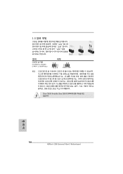
1.3 3 1-2 점퍼 CMOS 초기화 (CLRCMOS1, 3 2 26 세팅 CMOS 삭제 참고 : CLRCMOS1 CMOS 15 CLRCMOS1 의 핀 2 와 핀 3 을 5 BIOS CMOS BIOS CMOS CMOS CMOS 1394 GUID, MAC Clear CMOS Switch는 Clear CMOS 한 국 어 156 ASRock Z68 Extreme3 Gen3 Motherboard
1.3 3 1-2 점퍼 CMOS 초기화 (CLRCMOS1, 3 2 26 세팅 CMOS 삭제 참고 : CLRCMOS1 CMOS 15 CLRCMOS1 의 핀 2 와 핀 3 을 5 BIOS CMOS BIOS CMOS CMOS CMOS 1394 GUID, MAC Clear CMOS Switch는 Clear CMOS 한 국 어 156 ASRock Z68 Extreme3 Gen3 Motherboard

Quick Installation Guide
Page 167
...4 - LED(ACT/LINK LED および SPEED LED)付き RJ-45 LAN ポート x 1 CMOS x 1 8 参照 ) 167 ASRock Z68 Extreme3 Gen3 Motherboard 日本語 Premium Blu-ray THX TruStudioTM PCIE x1 Gigabit LAN 10/100/1000 Mb/s - PS/2 x 1 - eSATA3...光学 SPDIF x 1 - Intel® HD Intel® Quick Sync Video、Intel® InTruTM 3D、Intel® Clear Video HD Technology、Intel® HD Graphics 2000/3000、Intel® Advanced Vector Extensions (AVX) - Wake-On-LAN LAN Energy...
...4 - LED(ACT/LINK LED および SPEED LED)付き RJ-45 LAN ポート x 1 CMOS x 1 8 参照 ) 167 ASRock Z68 Extreme3 Gen3 Motherboard 日本語 Premium Blu-ray THX TruStudioTM PCIE x1 Gigabit LAN 10/100/1000 Mb/s - PS/2 x 1 - eSATA3...光学 SPDIF x 1 - Intel® HD Intel® Quick Sync Video、Intel® InTruTM 3D、Intel® Clear Video HD Technology、Intel® HD Graphics 2000/3000、Intel® Advanced Vector Extensions (AVX) - Wake-On-LAN LAN Energy...

Quick Installation Guide
Page 204
1.3 3 1 和針腳 2 CMOS (CLRCMOS1, 3 2 頁第 26 項 ) 設定 默認設置 清除 CMOS 註: C L R C M O S1 C M O S 15 CLRCMOS1 的 pin2 及 pin3 短路 5 BIOS CMOS BIOS CMOS CMOS C M O S 1394 GUID 及 MAC Clear CMOS Clear CMOS 繁體中文 204 ASRock Z68 Extreme3 Gen3 Motherboard
1.3 3 1 和針腳 2 CMOS (CLRCMOS1, 3 2 頁第 26 項 ) 設定 默認設置 清除 CMOS 註: C L R C M O S1 C M O S 15 CLRCMOS1 的 pin2 及 pin3 短路 5 BIOS CMOS BIOS CMOS CMOS C M O S 1394 GUID 及 MAC Clear CMOS Clear CMOS 繁體中文 204 ASRock Z68 Extreme3 Gen3 Motherboard

