
User Manual
Page 8
... Feature - 2 x SATA3 6.0Gb/s connectors - 1 x IR header - 1 x CIR header - 1 x COM port header - 1 x HDMI_SPDIF header - 1 x Power LED header - CPU/Chassis/Power FAN connector - 24 pin ATX power connector - 8 pin 12V power connector - ASRock SmartView (see CAUTION 16) - ASRock XFast USB (see CAUTION 15) - SMBIOS 2.3.1 Support - CPU Core, IGPU, DRAM, PCH, CPU PLL, VTT, VCCSA Voltage Multi-adjustment...
... Feature - 2 x SATA3 6.0Gb/s connectors - 1 x IR header - 1 x CIR header - 1 x COM port header - 1 x HDMI_SPDIF header - 1 x Power LED header - CPU/Chassis/Power FAN connector - 24 pin ATX power connector - 8 pin 12V power connector - ASRock SmartView (see CAUTION 16) - ASRock XFast USB (see CAUTION 15) - SMBIOS 2.3.1 Support - CPU Core, IGPU, DRAM, PCH, CPU PLL, VTT, VCCSA Voltage Multi-adjustment...

User Manual
Page 13
...CHA_FAN2 LAN PHY HDMI 1.4a 40 PCIE1 XFast USB AUDIO CODEC PCI Express 3.0 Z68 Extreme3 Gen3 39 PCIE2 Intel 10 SATA2_4_5 SATA2_2_3 SATA3_0_1 CMOS 38 PCIE3 Battery Super I/O 37 PCI1 SATA3 6Gb/s Z68 11 12 13 14 15 Designed in Taipei 36 35 RoHS HD_AUDIO1 1 HDMI_SPDIF1 1... 12V Power Connector (ATX12V1) 22 64Mb SPI Flash 2 1155-Pin CPU Socket 23 Chassis Fan Connector (CHA_FAN1) 3 Power Fan Connector (PWR_FAN1) 24 Dr. Debug 4 CPU Fan Connector (CPU_FAN1) 25 USB 2.0 Header (USB12_13, Black) 5 2 x 240-pin DDR3 DIMM Slots 26 Clear CMOS Jumper (CLRCMOS1) (Dual Channel...
...CHA_FAN2 LAN PHY HDMI 1.4a 40 PCIE1 XFast USB AUDIO CODEC PCI Express 3.0 Z68 Extreme3 Gen3 39 PCIE2 Intel 10 SATA2_4_5 SATA2_2_3 SATA3_0_1 CMOS 38 PCIE3 Battery Super I/O 37 PCI1 SATA3 6Gb/s Z68 11 12 13 14 15 Designed in Taipei 36 35 RoHS HD_AUDIO1 1 HDMI_SPDIF1 1... 12V Power Connector (ATX12V1) 22 64Mb SPI Flash 2 1155-Pin CPU Socket 23 Chassis Fan Connector (CHA_FAN1) 3 Power Fan Connector (PWR_FAN1) 24 Dr. Debug 4 CPU Fan Connector (CPU_FAN1) 25 USB 2.0 Header (USB12_13, Black) 5 2 x 240-pin DDR3 DIMM Slots 26 Clear CMOS Jumper (CLRCMOS1) (Dual Channel...
User Manual
Page 19
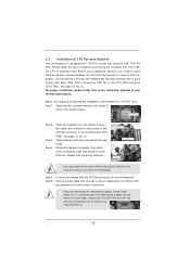
Before you installed the heatsink, you press down on fastener caps with 1155-Pin socket that supports Intel 1155-Pin CPU. Step 1. Apply Thermal Interface Material Step 2. Fan cables on side closest to MB header Fastener slots pointing straight out Press Down (4 Places) If you need ...Place the heatsink onto the socket. The white throughholes are oriented on side closest to the CPU fan connector on the motherboard. Ensure fan cables are for 1155-Pin CPU. Connect fan header with each other components. Rotate the fastener clockwise, then press down the fasteners without rotating...
Before you installed the heatsink, you press down on fastener caps with 1155-Pin socket that supports Intel 1155-Pin CPU. Step 1. Apply Thermal Interface Material Step 2. Fan cables on side closest to MB header Fastener slots pointing straight out Press Down (4 Places) If you need ...Place the heatsink onto the socket. The white throughholes are oriented on side closest to the CPU fan connector on the motherboard. Ensure fan cables are for 1155-Pin CPU. Connect fan header with each other components. Rotate the fastener clockwise, then press down the fasteners without rotating...

User Manual
Page 40
... indicate system power status. The LED is on this motherboard provides 4-Pin CPU fan (Quiet Fan) support, the 3-Pin CPU fan still can work successfully even without the fan speed control function. Please connect the chassis power LED to the CPU fan connector on when the system is off in S1 state. The LED... is operating. If you plan to connect the 3-Pin CPU fan to this header. CPU Fan Connectors (4-pin CPU_FAN1) (see p.13 No. 7) 40 The LED keeps blinking in S3/S4 state or S5 state (power off). Though this motherboard, please...
... indicate system power status. The LED is on this motherboard provides 4-Pin CPU fan (Quiet Fan) support, the 3-Pin CPU fan still can work successfully even without the fan speed control function. Please connect the chassis power LED to the CPU fan connector on when the system is off in S1 state. The LED... is operating. If you plan to connect the 3-Pin CPU fan to this header. CPU Fan Connectors (4-pin CPU_FAN1) (see p.13 No. 7) 40 The LED keeps blinking in S3/S4 state or S5 state (power off). Though this motherboard, please...

Quick Installation Guide
Page 2
... PWR_FAN1 CPU_FAN1 7 CPU_FAN2 PS2 Keyboard DX10.1 DDR3 2133 DVI_CON1 VGA1 30.5cm (12.0 in) DDR3_A2 (64 bit, 240-pin module) DDR3_B1 (64 bit, 240-pin module) DDR3_B2 (64 bit, 240-pin module) DDR3_A1 (64 bit, 240-pin module) HDMI1 Clr CMOS AT X P W R 1 eSATA_1 ErP/EuP Ready USB 2.0 T: USB2 B: USB3 8 USB 3.0 T: USB4 Top: B: USB5 RJ... 3.0 x16 Slot (PCIE2, Black) 20 System Panel Header (PANEL1, Black) 40 PCI Express 2.0 x1 Slot (PCIE1, Black) 21 Chassis Speaker Header (SPEAKER 1, Black) 41 Chassis Fan Connector (CHA_FAN3) 2 ASRock Z68 Extreme3 Gen3 Motherboard English
... PWR_FAN1 CPU_FAN1 7 CPU_FAN2 PS2 Keyboard DX10.1 DDR3 2133 DVI_CON1 VGA1 30.5cm (12.0 in) DDR3_A2 (64 bit, 240-pin module) DDR3_B1 (64 bit, 240-pin module) DDR3_B2 (64 bit, 240-pin module) DDR3_A1 (64 bit, 240-pin module) HDMI1 Clr CMOS AT X P W R 1 eSATA_1 ErP/EuP Ready USB 2.0 T: USB2 B: USB3 8 USB 3.0 T: USB4 Top: B: USB5 RJ... 3.0 x16 Slot (PCIE2, Black) 20 System Panel Header (PANEL1, Black) 40 PCI Express 2.0 x1 Slot (PCIE1, Black) 21 Chassis Speaker Header (SPEAKER 1, Black) 41 Chassis Fan Connector (CHA_FAN3) 2 ASRock Z68 Extreme3 Gen3 Motherboard English

Quick Installation Guide
Page 8
... BIOS - Hybrid Booster: - OEM) Unique Feature - Lucid Virtu (see CAUTION 12) - Supports "Plug and Play" - Good Night LED 8 ASRock Z68 Extreme3 Gen3 Motherboard ASRock SmartView (see CAUTION 15) - CPU/Chassis/Power FAN connector - 24 pin ATX power connector - 8 pin 12V power connector - Combo Cooler Option (C.C.O.) (see CAUTION 11) - ASRock APP Charger (see CAUTION 19) - ACPI 1.1 Compliance Wake Up Events...
... BIOS - Hybrid Booster: - OEM) Unique Feature - Lucid Virtu (see CAUTION 12) - Supports "Plug and Play" - Good Night LED 8 ASRock Z68 Extreme3 Gen3 Motherboard ASRock SmartView (see CAUTION 15) - CPU/Chassis/Power FAN connector - 24 pin ATX power connector - 8 pin 12V power connector - Combo Cooler Option (C.C.O.) (see CAUTION 11) - ASRock APP Charger (see CAUTION 19) - ACPI 1.1 Compliance Wake Up Events...
Quick Installation Guide
Page 15
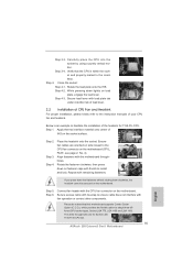
... plate tab under retention tab of load lever. 2.2 Installation of the heatsink for Socket LGA 1155/1156 CPU fan. 15 ASRock Z68 Extreme3 Gen3 Motherboard Step 6. Connect fan header with the motherboard throughholes. Please be noticed that the CPU is an example to MB header Fastener slots ... heatsink cannot be secured on the socket surface. Step 4-2. Ensure fan cables are for 1155-Pin CPU. Apply thermal interface material onto center of your CPU fan and heatsink. Secure excess cable with fan operation or contact other components. Verify that this motherboard supports Combo ...
... plate tab under retention tab of load lever. 2.2 Installation of the heatsink for Socket LGA 1155/1156 CPU fan. 15 ASRock Z68 Extreme3 Gen3 Motherboard Step 6. Connect fan header with the motherboard throughholes. Please be noticed that the CPU is an example to MB header Fastener slots ... heatsink cannot be secured on the socket surface. Step 4-2. Ensure fan cables are for 1155-Pin CPU. Apply thermal interface material onto center of your CPU fan and heatsink. Secure excess cable with fan operation or contact other components. Verify that this motherboard supports Combo ...

Quick Installation Guide
Page 35
... ). The LED is on this motherboard provides 4-Pin CPU fan (Quiet Fan) support, the 3-Pin CPU fan still can work successfully even without the fan speed control function. The LED is operating. Though this motherboard, please connect it to Pin 1-3. Pin 1-3 Connected 3-Pin Fan Installation (3-pin CPU_FAN2) (see p.2 No. 7) English 35 ASRock Z68 Extreme3 Gen3 Motherboard CPU Fan Connectors (4-pin CPU_FAN1) (see p.2 No. 4) FAN_SPEED_CONTROL CPU_FAN_SPEED +12V GND...
... ). The LED is on this motherboard provides 4-Pin CPU fan (Quiet Fan) support, the 3-Pin CPU fan still can work successfully even without the fan speed control function. The LED is operating. Though this motherboard, please connect it to Pin 1-3. Pin 1-3 Connected 3-Pin Fan Installation (3-pin CPU_FAN2) (see p.2 No. 7) English 35 ASRock Z68 Extreme3 Gen3 Motherboard CPU Fan Connectors (4-pin CPU_FAN1) (see p.2 No. 4) FAN_SPEED_CONTROL CPU_FAN_SPEED +12V GND...

Quick Installation Guide
Page 192
...) ( 見第 2 頁第 4 項 ) FAN_SPEED_CONTROL CPU_FAN_SPEED +12V GND 請將 CPU 1 2 3 4 4-Pin CPU 風扇 (Quiet Fan 3-Pin CPU 3-Pin CPU CPU Pin 1-3。 Pin 1-3 連接 3-Pin (3 針 CPU_FAN2) ( 見第 2 頁第 7 項 ) ATX (24 針 ATXPWR1) ( 見第 2 頁第 8 項 ) 12 24 1 13 請將 ATX 簡體中文 192 ASRock Z68 Extreme3 Gen3 Motherboard
...) ( 見第 2 頁第 4 項 ) FAN_SPEED_CONTROL CPU_FAN_SPEED +12V GND 請將 CPU 1 2 3 4 4-Pin CPU 風扇 (Quiet Fan 3-Pin CPU 3-Pin CPU CPU Pin 1-3。 Pin 1-3 連接 3-Pin (3 針 CPU_FAN2) ( 見第 2 頁第 7 項 ) ATX (24 針 ATXPWR1) ( 見第 2 頁第 8 項 ) 12 24 1 13 請將 ATX 簡體中文 192 ASRock Z68 Extreme3 Gen3 Motherboard

Quick Installation Guide
Page 208
...) ( 見第 2 頁第 4 項 ) FAN_SPEED_CONTROL CPU_FAN_SPEED +12V GND 請將 CPU 1 2 3 4 4-Pin CPU 風扇 (Quiet Fan 3-Pin CPU 3-Pin CPU CPU Pin 1-3。 Pin 1-3 連接 3-Pin (3 針 CPU_FAN2) ( 見第 2 頁第 7 項 ) ATX (24 針 ATXPWR1) ( 見第 2 頁第 8 項 ) 12 24 1 13 請將 ATX 208 ASRock Z68 Extreme3 Gen3 Motherboard 繁體中文
...) ( 見第 2 頁第 4 項 ) FAN_SPEED_CONTROL CPU_FAN_SPEED +12V GND 請將 CPU 1 2 3 4 4-Pin CPU 風扇 (Quiet Fan 3-Pin CPU 3-Pin CPU CPU Pin 1-3。 Pin 1-3 連接 3-Pin (3 針 CPU_FAN2) ( 見第 2 頁第 7 項 ) ATX (24 針 ATXPWR1) ( 見第 2 頁第 8 項 ) 12 24 1 13 請將 ATX 208 ASRock Z68 Extreme3 Gen3 Motherboard 繁體中文


