User Manual
Page 12
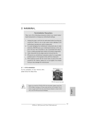
...shutdown. Frequencies other than 50% under 1.00W in off (or in ACPI S5 mode)! To improve heat dissipation, remember to adopt three different CPU cooler types, Socket LGA 775, LGA 1155 and LGA 1156. This motherboard also provides a free 3.5mm audio cable (optional) that not all the 775 and ...1156 CPU Fan can be noticed that ensures users the most convenient computing environment. 17. ASRock On/Off Play Technology allows users to enjoy the great ...
...shutdown. Frequencies other than 50% under 1.00W in off (or in ACPI S5 mode)! To improve heat dissipation, remember to adopt three different CPU cooler types, Socket LGA 775, LGA 1155 and LGA 1156. This motherboard also provides a free 3.5mm audio cable (optional) that not all the 775 and ...1156 CPU Fan can be noticed that ensures users the most convenient computing environment. 17. ASRock On/Off Play Technology allows users to enjoy the great ...

User Manual
Page 13
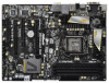
...3.0 CHA_FAN3 CHA_FAN2 LAN PHY HDMI 1.4a 40 PCIE1 XFast USB AUDIO CODEC PCI Express 3.0 Z68 Extreme3 Gen3 39 PCIE2 Intel 10 SATA2_4_5 SATA2_2_3 SATA3_0_1 CMOS 38 PCIE3 Battery Super I/O 37 PCI1 SATA3 6Gb/s Z68 11 12 13 14 15 Designed in Taipei 36 35 RoHS HD_AUDIO1 1 HDMI_SPDIF1 1 IR1 1...25 24 23 22 21 20 1 ATX 12V Power Connector (ATX12V1) 22 64Mb SPI Flash 2 1155-Pin CPU Socket 23 Chassis Fan Connector (CHA_FAN1) 3 Power Fan Connector (PWR_FAN1) 24 Dr. Debug 4 CPU Fan Connector (CPU_FAN1) 25 USB 2.0 Header (USB12_13, Black) 5 2 x 240-pin DDR3 DIMM Slots 26...
...3.0 CHA_FAN3 CHA_FAN2 LAN PHY HDMI 1.4a 40 PCIE1 XFast USB AUDIO CODEC PCI Express 3.0 Z68 Extreme3 Gen3 39 PCIE2 Intel 10 SATA2_4_5 SATA2_2_3 SATA3_0_1 CMOS 38 PCIE3 Battery Super I/O 37 PCI1 SATA3 6Gb/s Z68 11 12 13 14 15 Designed in Taipei 36 35 RoHS HD_AUDIO1 1 HDMI_SPDIF1 1 IR1 1...25 24 23 22 21 20 1 ATX 12V Power Connector (ATX12V1) 22 64Mb SPI Flash 2 1155-Pin CPU Socket 23 Chassis Fan Connector (CHA_FAN1) 3 Power Fan Connector (PWR_FAN1) 24 Dr. Debug 4 CPU Fan Connector (CPU_FAN1) 25 USB 2.0 Header (USB12_13, Black) 5 2 x 240-pin DDR3 DIMM Slots 26...

User Manual
Page 17
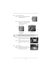
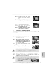
... Step 1-2. Remove PnP Cap (Pick and Place Cap). 1. Load Plate Load Lever Contact Array Socket Body 1155-Pin Socket Overview Before you insert the 1155-Pin CPU into the socket if above situation is recommended to use the cap tab to fully open position at approximately 100 ... Rotate the load lever to clear retention tab. Step 1. Step 2. Open the socket: Step 1-1. 2.3 CPU Installation For the installation of Intel 1155-Pin CPU, please follow the steps below. Otherwise, the CPU will be placed if returning the motherboard for after service. 17 Disengaging the lever ...
... Step 1-2. Remove PnP Cap (Pick and Place Cap). 1. Load Plate Load Lever Contact Array Socket Body 1155-Pin Socket Overview Before you insert the 1155-Pin CPU into the socket if above situation is recommended to use the cap tab to fully open position at approximately 100 ... Rotate the load lever to clear retention tab. Step 1. Step 2. Open the socket: Step 1-1. 2.3 CPU Installation For the installation of Intel 1155-Pin CPU, please follow the steps below. Otherwise, the CPU will be placed if returning the motherboard for after service. 17 Disengaging the lever ...
User Manual
Page 18
... load plate, engage the load lever. 18 Verify that the CPU is marked with black line. Carefully place the CPU into the socket by the edge where is within the socket and properly mated to match the two orientation key notches of the socket. Close the socket: Step 4-1. orientation key notch alignment key Pin1 Pin1 orientation...
... load plate, engage the load lever. 18 Verify that the CPU is marked with black line. Carefully place the CPU into the socket by the edge where is within the socket and properly mated to match the two orientation key notches of the socket. Close the socket: Step 4-1. orientation key notch alignment key Pin1 Pin1 orientation...
User Manual
Page 19
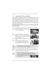
... and lock. For proper installation, please kindly refer to illustrate the installation of the heatsink for Socket LGA 1155/1156 CPU fan. 19 Below is equipped with Intel 1155Pin CPU to dissipate heat. Step 4. Rotate the fastener clockwise, then press down the fasteners without rotating them...Cooler Option (C.C.O.), which provides the flexible option to adopt three different CPU cooler types, Socket LGA 775, LGA 1155 and LGA 1156. Place the heatsink onto the socket. Connect fan header with the CPU fan connector on fastener caps with each other components. Step 6. Please be...
... and lock. For proper installation, please kindly refer to illustrate the installation of the heatsink for Socket LGA 1155/1156 CPU fan. 19 Below is equipped with Intel 1155Pin CPU to dissipate heat. Step 4. Rotate the fastener clockwise, then press down the fasteners without rotating them...Cooler Option (C.C.O.), which provides the flexible option to adopt three different CPU cooler types, Socket LGA 775, LGA 1155 and LGA 1156. Place the heatsink onto the socket. Connect fan header with the CPU fan connector on fastener caps with each other components. Step 6. Please be...

Quick Installation Guide
Page 2
...ATX 12V Power Connector (ATX12V1) 22 64Mb SPI Flash 2 1155-Pin CPU Socket 23 Chassis Fan Connector (CHA_FAN1) 3 Power Fan Connector (PWR_FAN1) 24 Dr. Debug 4 CPU Fan Connector (CPU_FAN1) 25 USB 2.0 Header (USB12_13, Black) 5...Slots 28 USB 2.0 Header (USB8_9, Black) (Dual Channel: DDR3_A2, DDR3_B2, Black) 29 USB 2.0 Header (USB6_7, Black) 7 CPU Fan Connector (CPU_FAN2) 30 Consumer Infrared Module Header 8 ATX Power Connector (ATXPWR1) (CIR1, Gray) 9 Chassis Fan Connector (CHA_FAN2...SPEAKER 1, Black) 41 Chassis Fan Connector (CHA_FAN3) 2 ASRock Z68 Extreme3 Gen3 Motherboard English
...ATX 12V Power Connector (ATX12V1) 22 64Mb SPI Flash 2 1155-Pin CPU Socket 23 Chassis Fan Connector (CHA_FAN1) 3 Power Fan Connector (PWR_FAN1) 24 Dr. Debug 4 CPU Fan Connector (CPU_FAN1) 25 USB 2.0 Header (USB12_13, Black) 5...Slots 28 USB 2.0 Header (USB8_9, Black) (Dual Channel: DDR3_A2, DDR3_B2, Black) 29 USB 2.0 Header (USB6_7, Black) 7 CPU Fan Connector (CPU_FAN2) 30 Consumer Infrared Module Header 8 ATX Power Connector (ATXPWR1) (CIR1, Gray) 9 Chassis Fan Connector (CHA_FAN2...SPEAKER 1, Black) 41 Chassis Fan Connector (CHA_FAN3) 2 ASRock Z68 Extreme3 Gen3 Motherboard English

Quick Installation Guide
Page 12
... not recommended to adopt three different CPU cooler types, Socket LGA 775, LGA 1155 and LGA 1156. Before you install the PC system. 19. Frequencies other than 50% under 1.00W in off (or in ACPI S5 mode)! EuP, stands for more details. 12 ASRock Z68 Extreme3 Gen3 Motherboard English While CPU overheat is turned off mode condition...
... not recommended to adopt three different CPU cooler types, Socket LGA 775, LGA 1155 and LGA 1156. Before you install the PC system. 19. Frequencies other than 50% under 1.00W in off (or in ACPI S5 mode)! EuP, stands for more details. 12 ASRock Z68 Extreme3 Gen3 Motherboard English While CPU overheat is turned off mode condition...
Quick Installation Guide
Page 13
.... 2. Installation Pre-installation Precautions Take note of Intel 1155-Pin CPU, please follow the steps below. Doing so may cause severe damage to the chassis, please do not touch the ICs. 4. English 13 ASRock Z68 Extreme3 Gen3 Motherboard Unplug the power cord from the wall socket before you uninstall any bent pin on a grounded antstatic pad...
.... 2. Installation Pre-installation Precautions Take note of Intel 1155-Pin CPU, please follow the steps below. Doing so may cause severe damage to the chassis, please do not touch the ICs. 4. English 13 ASRock Z68 Extreme3 Gen3 Motherboard Unplug the power cord from the wall socket before you uninstall any bent pin on a grounded antstatic pad...

Quick Installation Guide
Page 14
... for after service. Rotate the load plate to fully open position at approximately 100 degrees. Insert the 1155-Pin CPU: Step 3-1. Step 1-2. Step 3-2. Orient the CPU with the two alignment keys of the socket. 14 ASRock Z68 Extreme3 Gen3 Motherboard Step 1. Step 2. Remove PnP Cap (Pick and Place Cap). Locate Pin1 and the two orientation key notches...
... for after service. Rotate the load plate to fully open position at approximately 100 degrees. Insert the 1155-Pin CPU: Step 3-1. Step 1-2. Step 3-2. Orient the CPU with the two alignment keys of the socket. 14 ASRock Z68 Extreme3 Gen3 Motherboard Step 1. Step 2. Remove PnP Cap (Pick and Place Cap). Locate Pin1 and the two orientation key notches...
Quick Installation Guide
Page 15
.... Step 4. Verify that this motherboard supports Combo Cooler Option (C.C.O.), which provides the flexible option to the instruction manuals of the heatsink for Socket LGA 1155/1156 CPU fan. 15 ASRock Z68 Extreme3 Gen3 Motherboard Fan cables on the motherboard (CPU_ FAN1, see page 2, No. 4). Connect fan header with tie-wrap to install and lock. Step...
.... Step 4. Verify that this motherboard supports Combo Cooler Option (C.C.O.), which provides the flexible option to the instruction manuals of the heatsink for Socket LGA 1155/1156 CPU fan. 15 ASRock Z68 Extreme3 Gen3 Motherboard Fan cables on the motherboard (CPU_ FAN1, see page 2, No. 4). Connect fan header with tie-wrap to install and lock. Step...


