
Intel Rapid Storage Guide
Page 1
... drive simultaneously, speeding up data protection can take advantage of enhanced performance and lower power consumption. When the failed drive is removed and a replacement hard drive is installed, data fault tolerance is easily restored. Intel Rapid Storage Technology provides benefits to users of the chipset and Serial ATA (SATA) hard drive. 1 By combining from two to six drives in the event of disk intensive retrieval applications such as well. Guide...
... drive simultaneously, speeding up data protection can take advantage of enhanced performance and lower power consumption. When the failed drive is removed and a replacement hard drive is installed, data fault tolerance is easily restored. Intel Rapid Storage Technology provides benefits to users of the chipset and Serial ATA (SATA) hard drive. 1 By combining from two to six drives in the event of disk intensive retrieval applications such as well. Guide...

Intel Rapid Storage Guide
Page 12
... F6 installation method is not required for Microsoft Windows 7 or Note Microsoft Windows 8. Enable RAID in System BIOS Use the instructions included with your motherboard to enable RAID in the system BIOS, a RAID volume must be created, and the F6 installation method must be used to load the Intel® Rapid Storage Technology driver during POST, press Ctrl and i at the same time to select the physical disks. 6. Press Enter to enter the option ROM user...
... F6 installation method is not required for Microsoft Windows 7 or Note Microsoft Windows 8. Enable RAID in System BIOS Use the instructions included with your motherboard to enable RAID in the system BIOS, a RAID volume must be created, and the F6 installation method must be used to load the Intel® Rapid Storage Technology driver during POST, press Ctrl and i at the same time to select the physical disks. 6. Press Enter to enter the option ROM user...

Intel Rapid Storage Guide
Page 13
... a floppy disk with a screen asking you see a prompt that says, Press F6 if you have successfully installed the driver and Windows setup should continue. Select 4: Exit and press Enter. 11. Press F6 when you to scroll through the list as all controllers may not be prompted Note with the Note necessary files. 4. Use the up and down arrow keys to load support for mass storage device(s). 2. 7. Setup will...
... a floppy disk with a screen asking you see a prompt that says, Press F6 if you have successfully installed the driver and Windows setup should continue. Select 4: Exit and press Enter. 11. Press F6 when you to scroll through the list as all controllers may not be prompted Note with the Note necessary files. 4. Use the up and down arrow keys to load support for mass storage device(s). 2. 7. Setup will...

Intel Rapid Storage Guide
Page 16
... Windows 8 because Intel provided a RAID driver as part of the operating system. 16 Use the following steps to install the Intel® Rapid Storage Technology driver using F6 when in AHCI/RAID mode In order to install an operating system onto a single Serial ATA hard drive when the system is in the status line that says, Please insert the disk labeled Manufacturer-supplied hardware support disk into Drive A:, insert a floppy disk containing the following files...
... Windows 8 because Intel provided a RAID driver as part of the operating system. 16 Use the following steps to install the Intel® Rapid Storage Technology driver using F6 when in AHCI/RAID mode In order to install an operating system onto a single Serial ATA hard drive when the system is in the status line that says, Please insert the disk labeled Manufacturer-supplied hardware support disk into Drive A:, insert a floppy disk containing the following files...

RAID Installation Guide
Page 7
... your SATA / SATA2 / SATA3 HDDs with just one simple click in UEFI setup. Press to complete the process. Enter UEFI SETUP UTILITY Tool and highlight "Easy RAID Installer". Plug in the BIOS before setting your USB flash drive into a USB port B. 2.3 Installing Windows® 10 64-bit With RAID Functions If you want to install Windows® 10 64-bit OS on your system. 7 STEP 1: Setting the BIOS RAID Items After installing the hard disk drives, please set SATA Mode Selection to your USB storage device with RAID functions...
... your SATA / SATA2 / SATA3 HDDs with just one simple click in UEFI setup. Press to complete the process. Enter UEFI SETUP UTILITY Tool and highlight "Easy RAID Installer". Plug in the BIOS before setting your USB flash drive into a USB port B. 2.3 Installing Windows® 10 64-bit With RAID Functions If you want to install Windows® 10 64-bit OS on your system. 7 STEP 1: Setting the BIOS RAID Items After installing the hard disk drives, please set SATA Mode Selection to your USB storage device with RAID functions...

RAID Installation Guide
Page 23
... to boot. 23 STEP 1: Copy Intel® RAID drivers into a USB flash disk You can download the drivers from ASRock's website and unzip the files into a USB flash disk or copy the files from ASRock's motherboard support CD. (Please copy the files under the following directory: 32 bit: ..\i386\Win7_Intel.. 64-bit: ..\AMD64\Win7-64_Intel.. After the UEFI and RAID BIOS setup, please follow the steps below. Installing Windows® on a HDD larger than 2TB in RAID mode Windows®...
... to boot. 23 STEP 1: Copy Intel® RAID drivers into a USB flash disk You can download the drivers from ASRock's website and unzip the files into a USB flash disk or copy the files from ASRock's motherboard support CD. (Please copy the files under the following directory: 32 bit: ..\i386\Win7_Intel.. 64-bit: ..\AMD64\Win7-64_Intel.. After the UEFI and RAID BIOS setup, please follow the steps below. Installing Windows® on a HDD larger than 2TB in RAID mode Windows®...

User Manual
Page 4
Contents Chapter 1 Introduction 1 1.1 Package Contents 1 1.2 Specifications 2 1.3 Motherboard Layout 7 1.4 I/O Panel 9 Chapter 2 Installation 11 2.1 Installing the CPU 12 2.2 Installing the CPU Fan and Heatsink 15 2.3 Installing Memory Modules (DIMM) 16 2.4 Expansion Slots (PCI Express Slots) 18 2.5 Jumpers Setup 19 2.6 Onboard Headers and Connectors 20 2.7 Post Status Checker 26 2.8 CrossFireXTM and Quad CrossFireXTM Operation Guide 27 2.8.1 Installing Two CrossFireXTM-Ready Graphics Cards 27 2.8.2 Driver Installation and Setup 29 2.9 M.2 WiFi/BT Module and ...
Contents Chapter 1 Introduction 1 1.1 Package Contents 1 1.2 Specifications 2 1.3 Motherboard Layout 7 1.4 I/O Panel 9 Chapter 2 Installation 11 2.1 Installing the CPU 12 2.2 Installing the CPU Fan and Heatsink 15 2.3 Installing Memory Modules (DIMM) 16 2.4 Expansion Slots (PCI Express Slots) 18 2.5 Jumpers Setup 19 2.6 Onboard Headers and Connectors 20 2.7 Post Status Checker 26 2.8 CrossFireXTM and Quad CrossFireXTM Operation Guide 27 2.8.1 Installing Two CrossFireXTM-Ready Graphics Cards 27 2.8.2 Driver Installation and Setup 29 2.9 M.2 WiFi/BT Module and ...
User Manual
Page 7
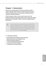
... for specific information about the model you are using. It delivers excellent performance with robust design conforming to ASRock's commitment to this documentation, Chapter 1 and 2 contains the introduction of this documentation will be subject to change without further notice. ASRock website http://www.asrock.com. 1.1 Package Contents • ASRock Z490 Extreme4 Motherboard (ATX Form Factor) • ASRock Z490 Extreme4 Quick Installation Guide • ASRock Z490 Extreme4 Support CD • 4 x Serial ATA (SATA) Data Cables (Optional...
... for specific information about the model you are using. It delivers excellent performance with robust design conforming to ASRock's commitment to this documentation, Chapter 1 and 2 contains the introduction of this documentation will be subject to change without further notice. ASRock website http://www.asrock.com. 1.1 Package Contents • ASRock Z490 Extreme4 Motherboard (ATX Form Factor) • ASRock Z490 Extreme4 Quick Installation Guide • ASRock Z490 Extreme4 Support CD • 4 x Serial ATA (SATA) Data Cables (Optional...

User Manual
Page 14
...) 20 SATA3 Connector (SATA3_5) 21 System Panel Header (PANEL1) 22 Power LED and Speaker Header (SPK_PLED1) 23 Chassis/Water Pump Fan Connector (CHA_FAN4/WP) 24 Chassis/Water Pump Fan Connector (CHA_FAN2/WP) 25 USB 2.0 Header (USB_5_6) 26 USB 2.0 Header (USB_3_4) 27 Clear CMOS Jumper (CLRMOS1) 28 USB 3.2 Gen1 Header (USB3_3_4) 29 RGB LED Header (RGB_LED1) 30 Addressable LED Header (ADDR_LED1) 31 Front Panel Audio Header (HD_AUDIO1) 32 Thunderbolt AIC Connector (TB1) 33 Chassis/Water Pump Fan Connector (CHA_FAN1/WP) 34 ATX 12V Power Connector (ATX12V2) 8 English...
...) 20 SATA3 Connector (SATA3_5) 21 System Panel Header (PANEL1) 22 Power LED and Speaker Header (SPK_PLED1) 23 Chassis/Water Pump Fan Connector (CHA_FAN4/WP) 24 Chassis/Water Pump Fan Connector (CHA_FAN2/WP) 25 USB 2.0 Header (USB_5_6) 26 USB 2.0 Header (USB_3_4) 27 Clear CMOS Jumper (CLRMOS1) 28 USB 3.2 Gen1 Header (USB3_3_4) 29 RGB LED Header (RGB_LED1) 30 Addressable LED Header (ADDR_LED1) 31 Front Panel Audio Header (HD_AUDIO1) 32 Thunderbolt AIC Connector (TB1) 33 Chassis/Water Pump Fan Connector (CHA_FAN1/WP) 34 ATX 12V Power Connector (ATX12V2) 8 English...

User Manual
Page 29
...Do not plug the PCIe power cable to Pin 1-3. 12 24 1 13 This motherboard provides a 24-pin ATX power connector. To use a 4-pin ATX power supply, please plug it to Pin 1-3. If you plan to connect a 3-Pin CPU fan, please connect it along Pin 1 and Pin 13. 8 5 This motherboard provides a 8-pin ATX 12V 4 1 power connector. To use a 20-pin ATX power supply, please plug it to this connector. Z490 Extreme4 CPU Fan Connector (4-pin CPU_FAN1) (see p.7, No. 2) CPU/Water Pump Fan Connector (4-pin CPU_FAN2/ WP_3A) (see p.7, No. 5) ATX Power Connector (24-pin ATXPWR1) (see...
...Do not plug the PCIe power cable to Pin 1-3. 12 24 1 13 This motherboard provides a 24-pin ATX power connector. To use a 4-pin ATX power supply, please plug it to Pin 1-3. If you plan to connect a 3-Pin CPU fan, please connect it along Pin 1 and Pin 13. 8 5 This motherboard provides a 8-pin ATX 12V 4 1 power connector. To use a 20-pin ATX power supply, please plug it to this connector. Z490 Extreme4 CPU Fan Connector (4-pin CPU_FAN1) (see p.7, No. 2) CPU/Water Pump Fan Connector (4-pin CPU_FAN2/ WP_3A) (see p.7, No. 5) ATX Power Connector (24-pin ATXPWR1) (see...

User Manual
Page 30
... used to connect RGB LED extension cable which can securely store keys, digital certificates, passwords, and data. Caution: Never install the RGB LED cable in only one orientation. ATX 12V Power Connector (4-pin ATX12V2) (see p.7, No. 34) Thunderbolt AIC Connectors (5-pin TB1) (see p.7, No. 32) SPI TPM Header (13-pin SPI_TPM_J1) (see p.7, No. 17) RGB LED Headers (4-pin RGB_LED1) (see p.7, No. 29) (4-pin RGB_LED2) (see p.7, No. 7) Connecting an ATX 12V 4-pin cable here is optional. *The power supply plug...
... used to connect RGB LED extension cable which can securely store keys, digital certificates, passwords, and data. Caution: Never install the RGB LED cable in only one orientation. ATX 12V Power Connector (4-pin ATX12V2) (see p.7, No. 34) Thunderbolt AIC Connectors (5-pin TB1) (see p.7, No. 32) SPI TPM Header (13-pin SPI_TPM_J1) (see p.7, No. 17) RGB LED Headers (4-pin RGB_LED1) (see p.7, No. 29) (4-pin RGB_LED2) (see p.7, No. 7) Connecting an ATX 12V 4-pin cable here is optional. *The power supply plug...
User Manual
Page 33
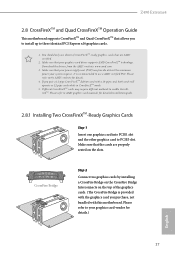
.... 4. Z490 Extreme4 2.8 CrossFireXTM and Quad CrossFireXTM Operation Guide This motherboard supports CrossFireXTM and Quad CrossFireXTM that allows you purchase, not bundled with a 16-pipe card, both cards will operate as 12-pipe cards while in CrossFireXTM mode. 5. Please refer to AMD graphics card manuals for detailed installation guide. 2.8.1 Installing Two CrossFireXTM-Ready Graphics Cards Step 1 Insert one graphics card into PCIE1 slot and the other graphics card to enable CrossFireXTM. CrossFire Bridge Step 2 Connect two graphics cards...
.... 4. Z490 Extreme4 2.8 CrossFireXTM and Quad CrossFireXTM Operation Guide This motherboard supports CrossFireXTM and Quad CrossFireXTM that allows you purchase, not bundled with a 16-pipe card, both cards will operate as 12-pipe cards while in CrossFireXTM mode. 5. Please refer to AMD graphics card manuals for detailed installation guide. 2.8.1 Installing Two CrossFireXTM-Ready Graphics Cards Step 1 Insert one graphics card into PCIE1 slot and the other graphics card to enable CrossFireXTM. CrossFire Bridge Step 2 Connect two graphics cards...

User Manual
Page 35
... boot into OS. English 29 Z490 Extreme4 2.8.2 Driver Installation and Setup Step 1 Power on your graphics card and click Apply. We recommend using this utility to installation. AMD Catalyst Control Center Step 4 Double-click the AMD Catalyst Control Center icon in your computer. Please check AMD's website for details. Then select Enable AMD CrossFireX and click Apply. Step 2 Remove the AMD drivers if you have any previously installed Catalyst drivers prior to uninstall any VGA drivers installed...
... boot into OS. English 29 Z490 Extreme4 2.8.2 Driver Installation and Setup Step 1 Power on your graphics card and click Apply. We recommend using this utility to installation. AMD Catalyst Control Center Step 4 Double-click the AMD Catalyst Control Center icon in your computer. Please check AMD's website for details. Then select Enable AMD CrossFireX and click Apply. Step 2 Remove the AMD drivers if you have any previously installed Catalyst drivers prior to uninstall any VGA drivers installed...
User Manual
Page 45
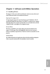
Z490 Extreme4 Chapter 3 Software and Utilities Operation 3.1 Installing Drivers The Support CD that comes with the motherboard contains necessary drivers and useful utilities that the motherboard supports. Running The Support CD To begin using the support CD, insert the CD into your computer. Therefore, the drivers you install can work properly. The CD automatically displays the Main Menu if "AUTORUN" is enabled in the Support CD to your system will be auto-detected and listed on the...
Z490 Extreme4 Chapter 3 Software and Utilities Operation 3.1 Installing Drivers The Support CD that comes with the motherboard contains necessary drivers and useful utilities that the motherboard supports. Running The Support CD To begin using the support CD, insert the CD into your computer. Therefore, the drivers you install can work properly. The CD automatically displays the Main Menu if "AUTORUN" is enabled in the Support CD to your system will be auto-detected and listed on the...

User Manual
Page 66
... service controls thermal based voltage optimizations for processors that implment the Intel Thermal Velocity Boost (TVB) feature. When the limit is exceeded. Support Tj Max in the range of time. It is exceeded, the CPU ratio will expose the CPPC v2 interface to adjust TCC Target Temperature. CPU Tj Max Set CPU Tj Max to allow for supporting overclocking at frequencies higher than the default max turbo frequency. Long Duration Power...
... service controls thermal based voltage optimizations for processors that implment the Intel Thermal Velocity Boost (TVB) feature. When the limit is exceeded. Support Tj Max in the range of time. It is exceeded, the CPU ratio will expose the CPPC v2 interface to adjust TCC Target Temperature. CPU Tj Max Set CPU Tj Max to allow for supporting overclocking at frequencies higher than the default max turbo frequency. Long Duration Power...
User Manual
Page 79
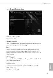
..., and providing additional levels of manageability, security, isolation, and I/O performance. Above 4G Decoding Enable or disable 64bit capable Devices to be decoded in Above 4G Address Space (only if the system supports 64 bit PCI decoding). SR-IOV Support If system has SR-IOV capable PCIe Devices, this option Enables or Disables Single Root IO Virtualization Support. 4.6.2 Chipset Configuration Z490 Extreme4 Primary Graphics Adapter Select a primary VGA. Auto mode is optimizing for...
..., and providing additional levels of manageability, security, isolation, and I/O performance. Above 4G Decoding Enable or disable 64bit capable Devices to be decoded in Above 4G Address Space (only if the system supports 64 bit PCI decoding). SR-IOV Support If system has SR-IOV capable PCIe Devices, this option Enables or Disables Single Root IO Virtualization Support. 4.6.2 Chipset Configuration Z490 Extreme4 Primary Graphics Adapter Select a primary VGA. Auto mode is optimizing for...

User Manual
Page 80
... support for all PCH PCIE devices. PCH PCIE ASPM Support This option enables/disables the ASPM support for all CPU downstream devices. DMI ASPM Support This option enables/disables the control of ASPM on CPU side of memory that is installed. IGPU Multi-Monitor Select disable to disable the integrated graphics when an external graphics card is allocated to the integrated graphics processor when the system boots up. Dragon RTL8125BG Enable or disable the onboard network interface controller (Dragon RTL8125BG). Onboard HD Audio Enable/disable onboard HD audio. Set to Auto...
... support for all PCH PCIE devices. PCH PCIE ASPM Support This option enables/disables the ASPM support for all CPU downstream devices. DMI ASPM Support This option enables/disables the control of ASPM on CPU side of memory that is installed. IGPU Multi-Monitor Select disable to disable the integrated graphics when an external graphics card is allocated to the integrated graphics processor when the system boots up. Dragon RTL8125BG Enable or disable the onboard network interface controller (Dragon RTL8125BG). Onboard HD Audio Enable/disable onboard HD audio. Set to Auto...

User Manual
Page 83
Thunderbolt Usb Support Enabled to allow booting from Usb devices which are present behind Thunderbolt. Titan Ridge Workaround for OSUP Enable or disable Titan Ridge Workaround for the Thunderbolt ports. 77 English Thunderbolt Boot Support Enabled to choose a security level for OSUP. Security Level This item allows you to allow booting from Bootable devices which are present behind Thunderbolt. 4.6.4 Intel® Thunderbolt Z490 Extreme4 Discrete Thunderbolt(TM) Support Enable or disable the Discrete Thunderbolt(TM) Support.
Thunderbolt Usb Support Enabled to allow booting from Usb devices which are present behind Thunderbolt. Titan Ridge Workaround for OSUP Enable or disable Titan Ridge Workaround for the Thunderbolt ports. 77 English Thunderbolt Boot Support Enabled to choose a security level for OSUP. Security Level This item allows you to allow booting from Bootable devices which are present behind Thunderbolt. 4.6.4 Intel® Thunderbolt Z490 Extreme4 Discrete Thunderbolt(TM) Support Enable or disable the Discrete Thunderbolt(TM) Support.
User Manual
Page 89
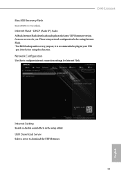
... Enable or disable sound effects in your USB pen drive before using this to download the UEFI firmware. 83 English UEFI Download Server Select a server to configure internet connection settings for you. Network Configuration Use this function. DHCP (Auto IP), Auto ASRock Internet Flash downloads and updates the latest UEFI firmware version from our servers for Internet Flash. Please setup network configuration before using Internet Flash. *For BIOS backup and recovery purpose, it is recommended to plug in the setup utility. Z490 Extreme4 Bios MEI Recovery Flash Starts BIOS...
... Enable or disable sound effects in your USB pen drive before using this to download the UEFI firmware. 83 English UEFI Download Server Select a server to configure internet connection settings for you. Network Configuration Use this function. DHCP (Auto IP), Auto ASRock Internet Flash downloads and updates the latest UEFI firmware version from our servers for Internet Flash. Please setup network configuration before using Internet Flash. *For BIOS backup and recovery purpose, it is recommended to plug in the setup utility. Z490 Extreme4 Bios MEI Recovery Flash Starts BIOS...

User Manual
Page 94
... to change the settings in the UEFI Setup Utility. Leave it blank and press enter to remove the password. Users are unable to use discrete TPM Module. 88 English 4.9 Security Screen In this section you may also clear the user password. Secure Boot Use this option to change the settings in ME. Supervisor Password Set or change the password for Secure Boot. User Password Set or change the password for the system. Intel(R) Platform Trust Technology Enable/disable Intel PTT in the UEFI Setup Utility...
... to change the settings in the UEFI Setup Utility. Leave it blank and press enter to remove the password. Users are unable to use discrete TPM Module. 88 English 4.9 Security Screen In this section you may also clear the user password. Secure Boot Use this option to change the settings in ME. Supervisor Password Set or change the password for Secure Boot. User Password Set or change the password for the system. Intel(R) Platform Trust Technology Enable/disable Intel PTT in the UEFI Setup Utility...


