
Intel Rapid Storage Guide
Page 12
... F6 installation method must be used to load the Intel® Rapid Storage Technology driver during POST, press Ctrl and i at the same time to enter the option ROM user interface. 2. Click F10 to enable RAID in System BIOS Use the instructions included with your motherboard to save the BIOS settings and exit the BIOS Setup program. When the Intel Rapid Storage Technology option ROM status screen appears during operating system setup. Enable RAID in the system BIOS. 1. Create a RAID Volume Use...
... F6 installation method must be used to load the Intel® Rapid Storage Technology driver during POST, press Ctrl and i at the same time to enter the option ROM user interface. 2. Click F10 to enable RAID in System BIOS Use the instructions included with your motherboard to save the BIOS settings and exit the BIOS Setup program. When the Intel Rapid Storage Technology option ROM status screen appears during operating system setup. Enable RAID in the system BIOS. 1. Create a RAID Volume Use...
Intel Rapid Storage Guide
Page 13
... when you need to create a floppy disk with a screen asking you have successfully installed the driver and Windows setup should continue. Setup will happen immediately after pressing F6. Press Enter. 5. Use the Floppy Configuration Utility to install a third party SCSI or RAID driver. Select the volume size and press Enter. 8. At this point, you to confirm volume creation. 10. At the prompt press Y to load support for mass storage device(s). 2. Leave 13
... when you need to create a floppy disk with a screen asking you have successfully installed the driver and Windows setup should continue. Setup will happen immediately after pressing F6. Press Enter. 5. Use the Floppy Configuration Utility to install a third party SCSI or RAID driver. Select the volume size and press Enter. 8. At this point, you to confirm volume creation. 10. At the prompt press Y to load support for mass storage device(s). 2. Leave 13

Intel Rapid Storage Guide
Page 16
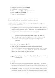
... F6. You can use a USB floppy drive or create a slipstream version of Windows setup (during text-mode phase). Press F6 when you see a prompt that says, Please insert the disk labeled Manufacturer-supplied hardware support disk into Drive A:, insert a floppy disk containing the following steps to install the Intel® Rapid Storage Technology driver using F6 when in AHCI/RAID mode In order to install an operating system onto a single Serial ATA hard drive when the system...
... F6. You can use a USB floppy drive or create a slipstream version of Windows setup (during text-mode phase). Press F6 when you see a prompt that says, Please insert the disk labeled Manufacturer-supplied hardware support disk into Drive A:, insert a floppy disk containing the following steps to install the Intel® Rapid Storage Technology driver using F6 when in AHCI/RAID mode In order to install an operating system onto a single Serial ATA hard drive when the system...

RAID Installation Guide
Page 7
... USB flash drive into a USB port B. 2.3 Installing Windows® 10 64-bit With RAID Functions If you want to install Windows® 10 64-bit OS on your SATA / SATA2 / SATA3 HDDs with just one simple click in UEFI setup. Plug in your system. 7 STEP 2: Use ASRock Easy RAID Installer Easy RAID Installer can copy the RAID driver from a support CD to your system, and press key to enter BIOS setup utility. Go to Advanced Storage Configuration and set SATA Mode Selection to confirm the selection C. Enter UEFI SETUP UTILITY...
... USB flash drive into a USB port B. 2.3 Installing Windows® 10 64-bit With RAID Functions If you want to install Windows® 10 64-bit OS on your SATA / SATA2 / SATA3 HDDs with just one simple click in UEFI setup. Plug in your system. 7 STEP 2: Use ASRock Easy RAID Installer Easy RAID Installer can copy the RAID driver from a support CD to your system, and press key to enter BIOS setup utility. Go to Advanced Storage Configuration and set SATA Mode Selection to confirm the selection C. Enter UEFI SETUP UTILITY...

Quick Installation Guide
Page 11
... can auto detect if 3-pin or 4-pin fan is in use. • 1 x 24 pin ATX Power Connector • 1 x 8 pin 12V Power Connector • 1 x Front Panel Audio Connector • 1 x Thunderbolt AIC Connector (5-pin) • 2 x USB 2.0 Headers (Support 3 USB 2.0 ports) (Supports ESD Protection) • 2 x USB 3.2 Gen1 Headers (Support 4 USB 3.2 Gen1 ports) (Supports ESD Protection) BIOS Feature • AMI UEFI Legal BIOS with multilingual GUI support • ACPI 6.0 Compliant wake up events • SMBIOS 2.7 Support • DRAM, PCH 1.0V, VCCIO, VCCST, VCCSA, VPPM Voltage Multi-adjustment...
... can auto detect if 3-pin or 4-pin fan is in use. • 1 x 24 pin ATX Power Connector • 1 x 8 pin 12V Power Connector • 1 x Front Panel Audio Connector • 1 x Thunderbolt AIC Connector (5-pin) • 2 x USB 2.0 Headers (Support 3 USB 2.0 ports) (Supports ESD Protection) • 2 x USB 3.2 Gen1 Headers (Support 4 USB 3.2 Gen1 ports) (Supports ESD Protection) BIOS Feature • AMI UEFI Legal BIOS with multilingual GUI support • ACPI 6.0 Compliant wake up events • SMBIOS 2.7 Support • DRAM, PCH 1.0V, VCCIO, VCCST, VCCSA, VPPM Voltage Multi-adjustment...

Quick Installation Guide
Page 28
... 12-pipe cards while in CrossFireXTM mode. 5. Download the drivers from the AMD's website: www.amd.com 3. Please refer to AMD graphics card manuals for details.) English 26 CrossFire Bridge Step 2 Connect two graphics cards by installing a CrossFire Bridge on the CrossFire Bridge Interconnects on the slots. Make sure that your power supply unit (PSU) can provide at least the minimum power your graphics card driver supports AMD CrossFireXTM technology. Different CrossFireXTM cards may require...
... 12-pipe cards while in CrossFireXTM mode. 5. Download the drivers from the AMD's website: www.amd.com 3. Please refer to AMD graphics card manuals for details.) English 26 CrossFire Bridge Step 2 Connect two graphics cards by installing a CrossFire Bridge on the CrossFire Bridge Interconnects on the slots. Make sure that your power supply unit (PSU) can provide at least the minimum power your graphics card driver supports AMD CrossFireXTM technology. Different CrossFireXTM cards may require...
Quick Installation Guide
Page 30
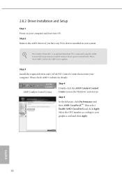
... recommend using this utility to installation. Step 3 Install the required drivers and CATALYST Control Center then restart your graphics card and click Apply. The Catalyst Uninstaller is an optional download. 2.8.2 Driver Installation and Setup Step 1 Power on your system. Step 2 Remove the AMD drivers if you have any previously installed Catalyst drivers prior to uninstall any VGA drivers installed in the Windows® system tray. AMD Catalyst Control Center Step 4 Double-click the AMD Catalyst Control Center...
... recommend using this utility to installation. Step 3 Install the required drivers and CATALYST Control Center then restart your graphics card and click Apply. The Catalyst Uninstaller is an optional download. 2.8.2 Driver Installation and Setup Step 1 Power on your system. Step 2 Remove the AMD drivers if you have any previously installed Catalyst drivers prior to uninstall any VGA drivers installed in the Windows® system tray. AMD Catalyst Control Center Step 4 Double-click the AMD Catalyst Control Center...

User Manual
Page 4
Contents Chapter 1 Introduction 1 1.1 Package Contents 1 1.2 Specifications 2 1.3 Motherboard Layout 7 1.4 I/O Panel 9 Chapter 2 Installation 11 2.1 Installing the CPU 12 2.2 Installing the CPU Fan and Heatsink 15 2.3 Installing Memory Modules (DIMM) 16 2.4 Expansion Slots (PCI Express Slots) 18 2.5 Jumpers Setup 19 2.6 Onboard Headers and Connectors 20 2.7 Post Status Checker 26 2.8 CrossFireXTM and Quad CrossFireXTM Operation Guide 27 2.8.1 Installing Two CrossFireXTM-Ready Graphics Cards 27 2.8.2 Driver Installation and Setup 29 2.9 M.2 WiFi/BT Module and ...
Contents Chapter 1 Introduction 1 1.1 Package Contents 1 1.2 Specifications 2 1.3 Motherboard Layout 7 1.4 I/O Panel 9 Chapter 2 Installation 11 2.1 Installing the CPU 12 2.2 Installing the CPU Fan and Heatsink 15 2.3 Installing Memory Modules (DIMM) 16 2.4 Expansion Slots (PCI Express Slots) 18 2.5 Jumpers Setup 19 2.6 Onboard Headers and Connectors 20 2.7 Post Status Checker 26 2.8 CrossFireXTM and Quad CrossFireXTM Operation Guide 27 2.8.1 Installing Two CrossFireXTM-Ready Graphics Cards 27 2.8.2 Driver Installation and Setup 29 2.9 M.2 WiFi/BT Module and ...
User Manual
Page 7
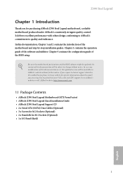
...motherboard specifications and the BIOS software might be updated, the content of this documentation occur, the updated version will be available on ASRock's website as well. ASRock website http://www.asrock.com. 1.1 Package Contents • ASRock Z390 Steel Legend Motherboard (ATX Form Factor) • ASRock Z390 Steel Legend Quick Installation Guide • ASRock Z390 Steel Legend Support CD • 2 x Serial ATA (SATA) Data Cables (Optional) • 3 x Screws for M.2 Sockets (Optional) • 2 x Standoffs for purchasing ASRock Z390 Steel Legend motherboard, a reliable motherboard...
...motherboard specifications and the BIOS software might be updated, the content of this documentation occur, the updated version will be available on ASRock's website as well. ASRock website http://www.asrock.com. 1.1 Package Contents • ASRock Z390 Steel Legend Motherboard (ATX Form Factor) • ASRock Z390 Steel Legend Quick Installation Guide • ASRock Z390 Steel Legend Support CD • 2 x Serial ATA (SATA) Data Cables (Optional) • 3 x Screws for M.2 Sockets (Optional) • 2 x Standoffs for purchasing ASRock Z390 Steel Legend motherboard, a reliable motherboard...

User Manual
Page 11
... can auto detect if 3-pin or 4-pin fan is in use. • 1 x 24 pin ATX Power Connector • 1 x 8 pin 12V Power Connector • 1 x Front Panel Audio Connector • 1 x Thunderbolt AIC Connector (5-pin) • 2 x USB 2.0 Headers (Support 3 USB 2.0 ports) (Supports ESD Protection) • 2 x USB 3.2 Gen1 Headers (Support 4 USB 3.2 Gen1 ports) (Supports ESD Protection) BIOS Feature • AMI UEFI Legal BIOS with multilingual GUI support • ACPI 6.0 Compliant wake up events • SMBIOS 2.7 Support • DRAM, PCH 1.0V, VCCIO, VCCST, VCCSA, VPPM Voltage Multi-adjustment...
... can auto detect if 3-pin or 4-pin fan is in use. • 1 x 24 pin ATX Power Connector • 1 x 8 pin 12V Power Connector • 1 x Front Panel Audio Connector • 1 x Thunderbolt AIC Connector (5-pin) • 2 x USB 2.0 Headers (Support 3 USB 2.0 ports) (Supports ESD Protection) • 2 x USB 3.2 Gen1 Headers (Support 4 USB 3.2 Gen1 ports) (Supports ESD Protection) BIOS Feature • AMI UEFI Legal BIOS with multilingual GUI support • ACPI 6.0 Compliant wake up events • SMBIOS 2.7 Support • DRAM, PCH 1.0V, VCCIO, VCCST, VCCSA, VPPM Voltage Multi-adjustment...

User Manual
Page 29
...13 This motherboard provides a 24-pin ATX power connector. ATX Power Connector (24-pin ATXPWR1) (see p.7, No. 2) +12V This motherboard pro- Z390 Steel Legend Chassis/Water Pump Fan Connectors (4-pin CHA_FAN1/WP) (see p.7, No. 18) (4-pin CHA_FAN2/WP) (see p.7, No. 29) (4-pin CHA_FAN3/WP) (see p.7, No. 17) 4 3 2 1 FAN_SPEED_CONTROL CHA_FAN_SPEED FAN_VOLTAGE GND This motherboard provides three 4-Pin water cooling chassis fan connectors. If you plan to connect a 3-Pin CPU water cooler fan, please connect it to Pin 1-3. To use a 4-pin ATX power supply, please plug it to Pin 1-3.
...13 This motherboard provides a 24-pin ATX power connector. ATX Power Connector (24-pin ATXPWR1) (see p.7, No. 2) +12V This motherboard pro- Z390 Steel Legend Chassis/Water Pump Fan Connectors (4-pin CHA_FAN1/WP) (see p.7, No. 18) (4-pin CHA_FAN2/WP) (see p.7, No. 29) (4-pin CHA_FAN3/WP) (see p.7, No. 17) 4 3 2 1 FAN_SPEED_CONTROL CHA_FAN_SPEED FAN_VOLTAGE GND This motherboard provides three 4-Pin water cooling chassis fan connectors. If you plan to connect a 3-Pin CPU water cooler fan, please connect it to Pin 1-3. To use a 4-pin ATX power supply, please plug it to Pin 1-3.

User Manual
Page 33
... the top of the graphics cards. (The CrossFire Bridge is recommended to enable CrossFireXTM. Z390 Steel Legend 2.8 CrossFireXTM and Quad CrossFireXTM Operation Guide This motherboard supports CrossFireXTM and Quad CrossFireXTM that allows you purchase, not bundled with a 16-pipe card, both cards will operate as 12-pipe cards while in CrossFireXTM mode. 5. You should only use a AMD certified PSU. Download the drivers from the AMD's website: www.amd.com 3.
... the top of the graphics cards. (The CrossFire Bridge is recommended to enable CrossFireXTM. Z390 Steel Legend 2.8 CrossFireXTM and Quad CrossFireXTM Operation Guide This motherboard supports CrossFireXTM and Quad CrossFireXTM that allows you purchase, not bundled with a 16-pipe card, both cards will operate as 12-pipe cards while in CrossFireXTM mode. 5. You should only use a AMD certified PSU. Download the drivers from the AMD's website: www.amd.com 3.

User Manual
Page 35
Z390 Steel Legend 2.8.2 Driver Installation and Setup Step 1 Power on your computer. AMD Catalyst Control Center Step 4 Double-click the AMD Catalyst Control Center icon in your graphics card and click Apply. The Catalyst Uninstaller is an optional download. We recommend using this utility to uninstall any VGA drivers installed in the Windows® system tray. English 29 Please check AMD's website for details. Please check AMD's website for AMD driver updates. Then select Enable AMD CrossFireX and click...
Z390 Steel Legend 2.8.2 Driver Installation and Setup Step 1 Power on your computer. AMD Catalyst Control Center Step 4 Double-click the AMD Catalyst Control Center icon in your graphics card and click Apply. The Catalyst Uninstaller is an optional download. We recommend using this utility to uninstall any VGA drivers installed in the Windows® system tray. English 29 Please check AMD's website for details. Please check AMD's website for AMD driver updates. Then select Enable AMD CrossFireX and click...
User Manual
Page 46
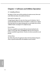
... install can work properly. Click on the support CD driver page. Please click Install All or follow the installation wizard to display the menu. The CD automatically displays the Main Menu if "AUTORUN" is enabled in the Support CD to install it. 40 English If the Main Menu does not appear automatically, locate and double click on the file "ASRSETUP.EXE" in your CD-ROM drive. Utilities Menu The Utilities Menu shows the application software...
... install can work properly. Click on the support CD driver page. Please click Install All or follow the installation wizard to display the menu. The CD automatically displays the Main Menu if "AUTORUN" is enabled in the Support CD to install it. 40 English If the Main Menu does not appear automatically, locate and double click on the file "ASRSETUP.EXE" in your CD-ROM drive. Utilities Menu The Utilities Menu shows the application software...

User Manual
Page 80
... enhanced PCI Express power saving in OS. Share Memory Configure the size of the DMI Link. Onboard HD Audio Enable/disable onboard HD audio. PCIE ASPM Support This option enables/disables the ASPM support for PCIE3. DMI ASPM Support This option enables/disables the control of ASPM on CPU side of memory that is allocated to disable the integrated graphics when an external graphics card is installed. 74 English PCIE3 Link Speed Select the link speed for all CPU downstream devices. IGPU Multi-Monitor Select disable...
... enhanced PCI Express power saving in OS. Share Memory Configure the size of the DMI Link. Onboard HD Audio Enable/disable onboard HD audio. PCIE ASPM Support This option enables/disables the ASPM support for PCIE3. DMI ASPM Support This option enables/disables the control of ASPM on CPU side of memory that is allocated to disable the integrated graphics when an external graphics card is installed. 74 English PCIE3 Link Speed Select the link speed for all CPU downstream devices. IGPU Multi-Monitor Select disable...
User Manual
Page 83
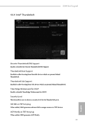
... for OSUP Enable or disable Titan Ridge Workaround for the Thunderbolt ports. SW SMI on TBT Hot-plug When enbled, BIOS generates ACPI Notify. 77 English Thunderbolt Usb Support Enabled to allow booting from Bootable devices which are present behind Thunderbolt. 4.6.4 Intel® Thunderbolt Z390 Steel Legend Discrete Thunderbolt(TM) Support Enable or disable the Discrete Thunderbolt(TM) Support. ACPI Notify on TBT hot-plug When enbled, BIOS generates software SMI to...
... for OSUP Enable or disable Titan Ridge Workaround for the Thunderbolt ports. SW SMI on TBT Hot-plug When enbled, BIOS generates ACPI Notify. 77 English Thunderbolt Usb Support Enabled to allow booting from Bootable devices which are present behind Thunderbolt. 4.6.4 Intel® Thunderbolt Z390 Steel Legend Discrete Thunderbolt(TM) Support Enable or disable the Discrete Thunderbolt(TM) Support. ACPI Notify on TBT hot-plug When enbled, BIOS generates software SMI to...

User Manual
Page 85
PS2 Y-Cable Enable the PS2 Y-Cable or set this option to Auto. 79 English Serial Port Address Select the address of the Serial port. 4.6.5 Super IO Configuration Z390 Steel Legend Serial Port Enable or disable the Serial port.
PS2 Y-Cable Enable the PS2 Y-Cable or set this option to Auto. 79 English Serial Port Address Select the address of the Serial port. 4.6.5 Super IO Configuration Z390 Steel Legend Serial Port Enable or disable the Serial port.

User Manual
Page 91
... USB storage device and run Instant Flash to any logging activation during reset. Instant Flash Save UEFI files in your UEFI. Internet Flash - Please setup network configuration before using Internet Flash. *For BIOS backup and recovery purpose, it is done prior to update your USB pen drive before using this to configure event log settings. Z390 Steel Legend Erase Event Log Choose options for you. Event Logs Use this function. 85 English DHCP (Auto IP), Auto ASRock Internet Flash downloads and updates the latest UEFI firmware version...
... USB storage device and run Instant Flash to any logging activation during reset. Instant Flash Save UEFI files in your UEFI. Internet Flash - Please setup network configuration before using Internet Flash. *For BIOS backup and recovery purpose, it is done prior to update your USB pen drive before using this to configure event log settings. Z390 Steel Legend Erase Event Log Choose options for you. Event Logs Use this function. 85 English DHCP (Auto IP), Auto ASRock Internet Flash downloads and updates the latest UEFI firmware version...

User Manual
Page 92
Network Configuration Use this to download the UEFI firmware. 86 English UEFI Download Server Select a server to configure internet connection settings for Internet Flash. Internet Setting Enable or disable sound effects in the setup utility.
Network Configuration Use this to download the UEFI firmware. 86 English UEFI Download Server Select a server to configure internet connection settings for Internet Flash. Internet Setting Enable or disable sound effects in the setup utility.

User Manual
Page 96
... press enter to remove the password. 4.9 Security Screen In this section you may also clear the user password. Only the administrator has authority to change the settings in ME. Users are unable to change the settings in the UEFI Setup Utility. Supervisor Password Set or change the supervisor/user password for Secure Boot. Secure Boot Use this option to enable or disable support for the system. Intel(R) Platform Trust Technology Enable/disable Intel PTT in the UEFI Setup Utility. You may set or change the password...
... press enter to remove the password. 4.9 Security Screen In this section you may also clear the user password. Only the administrator has authority to change the settings in ME. Users are unable to change the settings in the UEFI Setup Utility. Supervisor Password Set or change the supervisor/user password for Secure Boot. Secure Boot Use this option to enable or disable support for the system. Intel(R) Platform Trust Technology Enable/disable Intel PTT in the UEFI Setup Utility. You may set or change the password...


