

User Manual
Page 2
...gov/hazardouswaste/ perchlorate" ASRock Website: http://www.asrock.com ASRock assumes no event shall ASRock, its directors, oicers, employees, or agents be constructed as a commitment by ASRock. In no responsibility for a particular purpose. CALIFORNIA, USA ONLY he Lithium battery adopted on this motherboard contains Perchlorate, a ...including damages for loss of proits, loss of business, loss of data, interruption of business and the like), even if ASRock has been advised of the possibility of such damages arising from any means, except duplication of merchantability or itness for any ...
...gov/hazardouswaste/ perchlorate" ASRock Website: http://www.asrock.com ASRock assumes no event shall ASRock, its directors, oicers, employees, or agents be constructed as a commitment by ASRock. In no responsibility for a particular purpose. CALIFORNIA, USA ONLY he Lithium battery adopted on this motherboard contains Perchlorate, a ...including damages for loss of proits, loss of business, loss of data, interruption of business and the like), even if ASRock has been advised of the possibility of such damages arising from any means, except duplication of merchantability or itness for any ...
User Manual
Page 4
Contents Chapter 1 Introduction 1 1.1 Package Contents 1 1.2 Speciications 2 1.3 Motherboard Layout 7 1.4 I/O Panel 10 Chapter 2 Installation 12 2.1 Installing the CPU 13 2.2 Installing the CPU Fan and Heatsink 16 2.3 Installing Memory Modules (DIMM) 17 2.4 Expansion Slots (PCI ...
Contents Chapter 1 Introduction 1 1.1 Package Contents 1 1.2 Speciications 2 1.3 Motherboard Layout 7 1.4 I/O Panel 10 Chapter 2 Installation 12 2.1 Installing the CPU 13 2.2 Installing the CPU Fan and Heatsink 16 2.3 Installing Memory Modules (DIMM) 17 2.4 Expansion Slots (PCI ...
User Manual
Page 7
... step-by-step installation guides. Because the motherboard speciications and the BIOS sotware might be available on ASRock's website as well. Z170 OC Formula Chapter 1 Introduction hank you are using. ASRock website http://www.asrock.com. 1.1 Package Contents • ASRock Z170 OC Formula Motherboard (ATX Form Factor) • ASRock Z170 OC Formula Quick Installation Guide • ASRock Z170 OC Formula Support CD • 4 x Serial ATA (SATA) Data Cables (Optional) •...
... step-by-step installation guides. Because the motherboard speciications and the BIOS sotware might be available on ASRock's website as well. Z170 OC Formula Chapter 1 Introduction hank you are using. ASRock website http://www.asrock.com. 1.1 Package Contents • ASRock Z170 OC Formula Motherboard (ATX Form Factor) • ASRock Z170 OC Formula Quick Installation Guide • ASRock Z170 OC Formula Support CD • 4 x Serial ATA (SATA) Data Cables (Optional) •...
User Manual
Page 13
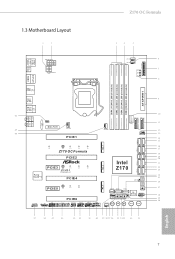
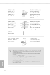
Z170 OC Formula 1.3 Motherboard Layout 1 2 3 4 5 USB 2.0 T: USB1 B: USB2 PS2 Keyboard /Mouse Clr CMOS ATX12V1 ATX12V2 VOL_CON1 6 CPU_FAN2 CHA_FAN4 7 CPU DRAM VGA BOOT 8 DISPLAY1 HDMI1 DDR4_A1 (64 bit, 288-pin ... 12 CHA_FAN1 13 14 15 SATA3_2 SATA3_0 M2_1 16 SATA3_3 SATA3_1 CT5 CT4 CT3 CT2 CT1 17 Z170 OC Formula 18 SATA_EXP1 SATA_EXP0 PCIE2 19 20 Intel SATA3_A3 SATA3_A4 21 M2_2 PCIE3 CT4 CT3 CT2 CT1 Ultra M.2 Z170 22 23 SATA3_A2 SATA3_A1 PCIe Gen3 x4 Purity SoundTM 3 PCIE4 BIOS_B_LED BIOS_A_LED BIOS_B1 128Mb BIOS BIOS_A1...
Z170 OC Formula 1.3 Motherboard Layout 1 2 3 4 5 USB 2.0 T: USB1 B: USB2 PS2 Keyboard /Mouse Clr CMOS ATX12V1 ATX12V2 VOL_CON1 6 CPU_FAN2 CHA_FAN4 7 CPU DRAM VGA BOOT 8 DISPLAY1 HDMI1 DDR4_A1 (64 bit, 288-pin ... 12 CHA_FAN1 13 14 15 SATA3_2 SATA3_0 M2_1 16 SATA3_3 SATA3_1 CT5 CT4 CT3 CT2 CT1 17 Z170 OC Formula 18 SATA_EXP1 SATA_EXP0 PCIE2 19 20 Intel SATA3_A3 SATA3_A4 21 M2_2 PCIE3 CT4 CT3 CT2 CT1 Ultra M.2 Z170 22 23 SATA3_A2 SATA3_A1 PCIe Gen3 x4 Purity SoundTM 3 PCIE4 BIOS_B_LED BIOS_A_LED BIOS_B1 128Mb BIOS BIOS_A1...
User Manual
Page 18
... touch the ICs. • Whenever you uninstall any motherboard settings. • Make sure to unplug the power cord before you install the motherboard, study the coniguration of the following precautions before installing or removing the motherboard components. Failure to ensure that comes with the components....; When placing screws to secure the motherboard to the chassis, please do so may damage the motherboard. 12 English Pre-installation Precautions Take note of your motherboard directly on a grounded anti-static pad or in the bag that the motherboard its into it. Doing so may...
... touch the ICs. • Whenever you uninstall any motherboard settings. • Make sure to unplug the power cord before you install the motherboard, study the coniguration of the following precautions before installing or removing the motherboard components. Failure to ensure that comes with the components....; When placing screws to secure the motherboard to the chassis, please do so may damage the motherboard. 12 English Pre-installation Precautions Take note of your motherboard directly on a grounded anti-static pad or in the bag that the motherboard its into it. Doing so may...

User Manual
Page 21
he cover must be placed if you wish to return the motherboard for ater service. 15 English Z170 OC Formula Please save and replace the cover if the processor is removed.
he cover must be placed if you wish to return the motherboard for ater service. 15 English Z170 OC Formula Please save and replace the cover if the processor is removed.
User Manual
Page 23
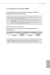
... DIMM may be damaged. English 17 For dual channel coniguration, you always need to the motherboard and the DIMM if you install two memory modules, make sure to activate Dual Channel Memory Technology with only one correct orientation. It... size and chip-type) DDR4 DIMM pairs. 2. Dual Channel Memory Coniguration If you force the DIMM into the slot at incorrect orientation. Z170 OC Formula 2.3 Installing Memory Modules (DIMM) his motherboard provides four 288-pin DDR4 (Double Data Rate 4) DIMM slots, and supports Dual Channel Memory Technology. 1. It is not allowed to install...
... DIMM may be damaged. English 17 For dual channel coniguration, you always need to the motherboard and the DIMM if you install two memory modules, make sure to activate Dual Channel Memory Technology with only one correct orientation. It... size and chip-type) DDR4 DIMM pairs. 2. Dual Channel Memory Coniguration If you force the DIMM into the slot at incorrect orientation. Z170 OC Formula 2.3 Installing Memory Modules (DIMM) his motherboard provides four 288-pin DDR4 (Double Data Rate 4) DIMM slots, and supports Dual Channel Memory Technology. 1. It is not allowed to install...
User Manual
Page 25
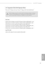
Z170 OC Formula 2.4 Expansion Slots (PCI Express Slots) here are 6 PCI Express slots and 1 mini-PCI Express slot on the motherboard. Before installing an expansion card, please make sure that the power supply is switched of the expansion card and make necessary hardware settings for PCI ...
Z170 OC Formula 2.4 Expansion Slots (PCI Express Slots) here are 6 PCI Express slots and 1 mini-PCI Express slot on the motherboard. Before installing an expansion card, please make sure that the power supply is switched of the expansion card and make necessary hardware settings for PCI ...
User Manual
Page 26
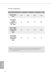
PCIe Slot Conigurations Single Graphics Card PCIE1 x16 Two Graphics Cards in CrossFireXTM or x8 SLITM Mode hree Graphics Cards in 3-Way CrossFireXTM x8 Mode Four Graphics Cards in 4-Way CrossFireXTM x8 Mode PCIE2 N/A N/A x4 x4 PCIE4 N/A x8 x8 x4 PCIE6 N/A N/A N/A x4 For a better thermal environment, please connect a chassis fan to the motherboard's chassis fan connector (CHA_FAN1, CHA_FAN2, CHA_FAN3 or CHA_FAN4) when using multiple graphics cards. English 20
PCIe Slot Conigurations Single Graphics Card PCIE1 x16 Two Graphics Cards in CrossFireXTM or x8 SLITM Mode hree Graphics Cards in 3-Way CrossFireXTM x8 Mode Four Graphics Cards in 4-Way CrossFireXTM x8 Mode PCIE2 N/A N/A x4 x4 PCIE4 N/A x8 x8 x4 PCIE6 N/A N/A N/A x4 For a better thermal environment, please connect a chassis fan to the motherboard's chassis fan connector (CHA_FAN1, CHA_FAN2, CHA_FAN3 or CHA_FAN4) when using multiple graphics cards. English 20
User Manual
Page 28
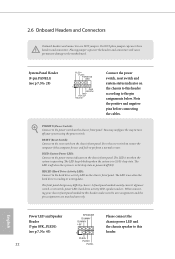
... hard drive activity LED on the chassis front panel. Press the reset switch to restart the computer if the computer freezes and fails to the motherboard. 2.6 Onboard Headers and Connectors Onboard headers and connectors are matched correctly. he front panel design may conigure the way to the reset switch on the...
... hard drive activity LED on the chassis front panel. Press the reset switch to restart the computer if the computer freezes and fails to the motherboard. 2.6 Onboard Headers and Connectors Onboard headers and connectors are matched correctly. he front panel design may conigure the way to the reset switch on the...
User Manual
Page 30
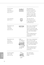
...for the HD audio panel only. Connect Ground (GND) to MIC2_L. High Deinition Audio supports Jack Sensing, but the panel wire on this motherboard. Connect Mic_IN (MIC) to Ground (GND). To activate the front mic, go to the "FrontMic" Tab in our manual and chassis manual...+ Vbus IntA_PB_SSRXIntA_PB_SSRX+ GND IntA_PB_SSTXIntA_PB_SSTX+ GND IntA_PB_DIntA_PB_D+ Dummy 1 Besides six USB 3.0 ports on the I /O panel, there are two headers on this motherboard. MIC_RET and OUT_RET are two headers and one port on the chassis must support HDA to install your system. 2.
...for the HD audio panel only. Connect Ground (GND) to MIC2_L. High Deinition Audio supports Jack Sensing, but the panel wire on this motherboard. Connect Mic_IN (MIC) to Ground (GND). To activate the front mic, go to the "FrontMic" Tab in our manual and chassis manual...+ Vbus IntA_PB_SSRXIntA_PB_SSRX+ GND IntA_PB_SSTXIntA_PB_SSTX+ GND IntA_PB_DIntA_PB_D+ Dummy 1 Besides six USB 3.0 ports on the I /O panel, there are two headers on this motherboard. MIC_RET and OUT_RET are two headers and one port on the chassis must support HDA to install your system. 2.
User Manual
Page 31
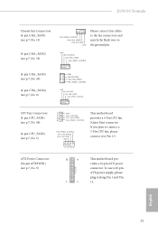
... CPU_FAN1) (see p.7, No. 48) (4-pin CPU_FAN2) (see p.7, No. 9) 12 24 1 13 his motherboard provides a 4-Pin CPU fan (Quiet Fan) connector. English 25 If you plan to connect a 3-Pin CPU fan, please connect it along Pin 1 and Pin 13. Z170 OC Formula Chassis Fan Connectors (4-pin CHA_FAN1) (see p.7, No. 13) (4-pin CHA_FAN2) (see p.7, No. 38...
... CPU_FAN1) (see p.7, No. 48) (4-pin CPU_FAN2) (see p.7, No. 9) 12 24 1 13 his motherboard provides a 4-Pin CPU fan (Quiet Fan) connector. English 25 If you plan to connect a 3-Pin CPU fan, please connect it along Pin 1 and Pin 13. Z170 OC Formula Chassis Fan Connectors (4-pin CHA_FAN1) (see p.7, No. 13) (4-pin CHA_FAN2) (see p.7, No. 38...
User Manual
Page 32
...Please connect a hunderbolt™ add-in card (AIC) to this connector via the GPIO cable. *Please install the hunderbolt™ AIC card to the motherboard. Please connect a hunderbolt™ add-in card (AIC) to this connector via the GPIO cable. *Please install the hunderbolt™ AIC card to ... one hunderbolt AIC Card is used to supply additional power to PCIE2 (default slot). *Only one hunderbolt AIC Card is supported on this motherboard. To use a 4-pin ATX power supply, please plug it along Pin 1 and Pin 5. *he 4-pin ATX 12V power connector is supported on ...
...Please connect a hunderbolt™ add-in card (AIC) to this connector via the GPIO cable. *Please install the hunderbolt™ AIC card to the motherboard. Please connect a hunderbolt™ add-in card (AIC) to this connector via the GPIO cable. *Please install the hunderbolt™ AIC card to ... one hunderbolt AIC Card is used to supply additional power to PCIE2 (default slot). *Only one hunderbolt AIC Card is supported on this motherboard. To use a 4-pin ATX power supply, please plug it along Pin 1 and Pin 5. *he 4-pin ATX 12V power connector is supported on ...
User Manual
Page 34
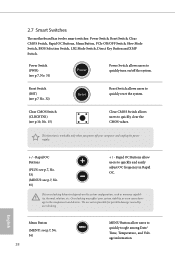
...solution, etc. Menu Button (MENU: see p.7, No. - 35) + / - his function is workable only when you power of the system. English Rapid OC Buttons + (PLUS: see p.7, No. 33) (MINUS: see p.7, No. 36) 28 MENU MENU Button allow users to quickly toogle among Date/ Time,... Temperature, and Voltage information. Rapid OC Buttons allow users to quickly and easily adjust OC frequency in Rapid OC. 2.7 Smart Switches he motherboard has twelve smart switches: Power Switch, Reset Switch, Clear CMOS Switch, Rapid OC Buttons, Menu Button, PCIe ON/OFF Switch, Slow...
...solution, etc. Menu Button (MENU: see p.7, No. - 35) + / - his function is workable only when you power of the system. English Rapid OC Buttons + (PLUS: see p.7, No. 33) (MINUS: see p.7, No. 36) 28 MENU MENU Button allow users to quickly toogle among Date/ Time,... Temperature, and Voltage information. Rapid OC Buttons allow users to quickly and easily adjust OC frequency in Rapid OC. 2.7 Smart Switches he motherboard has twelve smart switches: Power Switch, Reset Switch, Clear CMOS Switch, Rapid OC Buttons, Menu Button, PCIe ON/OFF Switch, Slow...
User Manual
Page 35
Z170 OC Formula PCIe ON/OFF Switch (SWITCH1) (see p.7, No. 39) ON 1234 1: PCIE1 2: PCIE2 3: PCIE4 4: ...When you power of the system before changing the switch. 2. For safety issues, users are not able to boot from the motherboard. OFF quency. BIOS Selection Switch (BIOS_SEL1) (see p.7, No. 34) ON If Slow Mode is on the primary BIOS.... For more information about your PCIE card, please remove it was poorly designed. his motherboard has two BIOS chips, a primary BIOS (BIOS_A) and a backup BIOS (BIOS_ B), which BIOS is out of the BIOS ...
Z170 OC Formula PCIe ON/OFF Switch (SWITCH1) (see p.7, No. 39) ON 1234 1: PCIE1 2: PCIE2 3: PCIE4 4: ...When you power of the system before changing the switch. 2. For safety issues, users are not able to boot from the motherboard. OFF quency. BIOS Selection Switch (BIOS_SEL1) (see p.7, No. 34) ON If Slow Mode is on the primary BIOS.... For more information about your PCIE card, please remove it was poorly designed. his motherboard has two BIOS chips, a primary BIOS (BIOS_A) and a backup BIOS (BIOS_ B), which BIOS is out of the BIOS ...

User Manual
Page 40
... graphics card into PCIE1 slot and the other graphics card to the PCI Express graphics cards. 34 English 2.9 SLITM and Quad SLITM Operation Guide his motherboard supports NVIDIA® SLITM and Quad SLITM (Scalable Link Interface) technology that allows you to install up to use identical SLITM-ready graphics cards that...
... graphics card into PCIE1 slot and the other graphics card to the PCI Express graphics cards. 34 English 2.9 SLITM and Quad SLITM Operation Guide his motherboard supports NVIDIA® SLITM and Quad SLITM (Scalable Link Interface) technology that allows you to install up to use identical SLITM-ready graphics cards that...
User Manual
Page 43
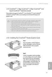
... the CrossFire Bridge Interconnects on the slots. If you pair a 12-pipe CrossFireXTM Edition card with this motherboard. Please refer to PCIE4 slot. Z170 OC Formula 2.10 CrossFireXTM, 3-Way CrossFireXTM, 4-Way CrossFireXTM and Quad CrossFireXTM Operation Guide his motherboard supports CrossFireXTM, 3-way CrossFireXTM, 4-way CrossFireXTM and Quad CrossFireXTM allows you to install up to enable...
... the CrossFire Bridge Interconnects on the slots. If you pair a 12-pipe CrossFireXTM Edition card with this motherboard. Please refer to PCIE4 slot. Z170 OC Formula 2.10 CrossFireXTM, 3-Way CrossFireXTM, 4-Way CrossFireXTM and Quad CrossFireXTM Operation Guide his motherboard supports CrossFireXTM, 3-way CrossFireXTM, 4-way CrossFireXTM and Quad CrossFireXTM allows you to install up to enable...
User Manual
Page 45
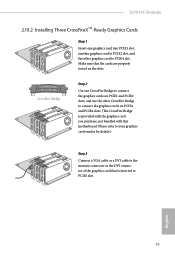
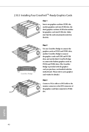
Z170 OC Formula 2.10.2 Installing Three CrossFireXTM-Ready Graphics Cards Step 1 Insert one CrossFire Bridge to connect the graphics cards on PCIE1 and PCIE2 slots, and use the ... the cards are properly seated on PCIE2 and PCIE4 slots. (he CrossFire Bridge is provided with the graphics card you purchase, not bundled with this motherboard.
Z170 OC Formula 2.10.2 Installing Three CrossFireXTM-Ready Graphics Cards Step 1 Insert one CrossFire Bridge to connect the graphics cards on PCIE1 and PCIE2 slots, and use the ... the cards are properly seated on PCIE2 and PCIE4 slots. (he CrossFire Bridge is provided with the graphics card you purchase, not bundled with this motherboard.
User Manual
Page 46
... PCIE4 slot and the last graphics card into PCIE6 slot. Make sure that is provided with the graphics card you purchase, not bundled with this motherboard. Please refer to your graphics card vendor for details.) Step 3 Connect a VGA cable or a DVI cable to the monitor connector or the DVI connector of...
... PCIE4 slot and the last graphics card into PCIE6 slot. Make sure that is provided with the graphics card you purchase, not bundled with this motherboard. Please refer to your graphics card vendor for details.) Step 3 Connect a VGA cable or a DVI cable to the monitor connector or the DVI connector of...
User Manual
Page 49
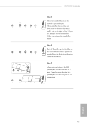
... orientation. Step 5 Align and gently insert the M.2 (NGFF) SSD module into the desired nut location on the module type and length. E D C B A E D C B A C B A E D C B A Z170 OC Formula Step 3 Move the standof based on the motherboard. Step 4 Peel of the yellow protective ilm on the nut to use the default nut. Hand tighten the standof into the M.2 slot...
... orientation. Step 5 Align and gently insert the M.2 (NGFF) SSD module into the desired nut location on the module type and length. E D C B A E D C B A C B A E D C B A Z170 OC Formula Step 3 Move the standof based on the motherboard. Step 4 Peel of the yellow protective ilm on the nut to use the default nut. Hand tighten the standof into the M.2 slot...

