
User Manual
Page 7
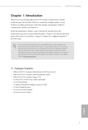
... this documentation occur, the updated version will be available on ASRock's website as well. ASRock website http://www.asrock.com. 1.1 Package Contents • ASRock Z170 OC Formula Motherboard (ATX Form Factor) • ASRock Z170 OC Formula Quick Installation Guide • ASRock Z170 OC Formula Support CD • 4 x Serial ATA (SATA) Data Cables (Optional) • 1 x I/O Panel Shield • 1 x ASRock Flexible SLI Bridge Connector Cable • 1 x WiFi Module Bracket...
... this documentation occur, the updated version will be available on ASRock's website as well. ASRock website http://www.asrock.com. 1.1 Package Contents • ASRock Z170 OC Formula Motherboard (ATX Form Factor) • ASRock Z170 OC Formula Quick Installation Guide • ASRock Z170 OC Formula Support CD • 4 x Serial ATA (SATA) Data Cables (Optional) • 1 x I/O Panel Shield • 1 x ASRock Flexible SLI Bridge Connector Cable • 1 x WiFi Module Bracket...
User Manual
Page 8
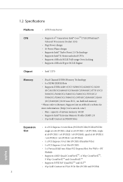
...• 15μ Gold Contact in VGA PCIe Slot (PCIE1 and PCIE4) 2 English 1.2 Speciications Platform • ATX Form Factor CPU • Supports 6th Generation Intel® CoreTM i7/i5/i3/Pentium®/ Celeron® Processors (...ASRock Hyper BCLK Engine Chipset • Intel® Z170 Memory • Dual Channel DDR4 Memory Technology • 4 x DDR4 DIMM Slots • Supports DDR4 4400+(OC)*/4300(OC)/4266(OC) /4200 (OC)/4133(OC)/4000(OC)/3866(OC)/3800(OC)/3733 (OC)/ 3666(OC)/3600(OC)/3466(OC)/3400(OC)/3333(OC)/ 3300(OC)/3200(OC)/3000(OC)/2933(OC)/2800(OC)/2600 (OC)/2400(OC...
...• 15μ Gold Contact in VGA PCIe Slot (PCIE1 and PCIE4) 2 English 1.2 Speciications Platform • ATX Form Factor CPU • Supports 6th Generation Intel® CoreTM i7/i5/i3/Pentium®/ Celeron® Processors (...ASRock Hyper BCLK Engine Chipset • Intel® Z170 Memory • Dual Channel DDR4 Memory Technology • 4 x DDR4 DIMM Slots • Supports DDR4 4400+(OC)*/4300(OC)/4266(OC) /4200 (OC)/4133(OC)/4000(OC)/3866(OC)/3800(OC)/3733 (OC)/ 3666(OC)/3600(OC)/3466(OC)/3400(OC)/3333(OC)/ 3300(OC)/3200(OC)/3000(OC)/2933(OC)/2800(OC)/2600 (OC)/2400(OC...
User Manual
Page 11
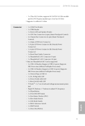
Z170 OC Formula • 3 x Ultra M.2 Sockets, supports M.2 SATA3 6.0 Gb/s module and M.2 PCI Express module up to adjust OC frequency • 1 x Menu Button • 1 x PCIe ON/OFF Switch • 1 x Post Status Checker (PSC) • 1 x Slow Mode Switch • 1 x...(32 Gb/s) * Supports 3 x ASRock U.2 Kits Connector • 1 x COM Port Header • 1 x TPM Header • 1 x Power LED and Speaker Header • 2 x CPU Fan Connectors (4-pin) (Smart Fan Speed Control) • 4 x Chassis Fan Connectors (4-pin) (Smart Fan Speed Control) • 1 x 24 pin ATX Power Connector • 1 x ...
Z170 OC Formula • 3 x Ultra M.2 Sockets, supports M.2 SATA3 6.0 Gb/s module and M.2 PCI Express module up to adjust OC frequency • 1 x Menu Button • 1 x PCIe ON/OFF Switch • 1 x Post Status Checker (PSC) • 1 x Slow Mode Switch • 1 x...(32 Gb/s) * Supports 3 x ASRock U.2 Kits Connector • 1 x COM Port Header • 1 x TPM Header • 1 x Power LED and Speaker Header • 2 x CPU Fan Connectors (4-pin) (Smart Fan Speed Control) • 4 x Chassis Fan Connectors (4-pin) (Smart Fan Speed Control) • 1 x 24 pin ATX Power Connector • 1 x ...
User Manual
Page 14
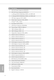
... DIMM Slots (DDR3_A1, DDR3_B1) 4 2 x 288-pin DDR3 DIMM Slots (DDR3_A2, DDR3_B2) 5 CPU Fan Connector (CPU_FAN2) 6 Chassis Fan Connector (CHA_FAN4) 7 V-ProbeTM (VOL_CON1) 8 Post Status Checker (PSC) 9 ATX Power Connector (ATXPWR1) 10 Vertical Type A USB 3.0 (USB3_9) 11 USB 3.0 Header (USB3_5_6) 12 USB 3.0 Header (USB3_7_8) 13 Chassis Fan Connector (CHA_FAN1) 14 SATA3 Connector (SATA3_0... (BIOS_SEL1) 28 System Panel Header (PANEL1) 29 Direct Key Button (DIRKEY1) 30 XMP Switch (XMP_ON1) 31 Power Switch (PWR) 32 Reset Switch (RST) 33 Rapid OC Button (+) (PLUS) 8 English No.
... DIMM Slots (DDR3_A1, DDR3_B1) 4 2 x 288-pin DDR3 DIMM Slots (DDR3_A2, DDR3_B2) 5 CPU Fan Connector (CPU_FAN2) 6 Chassis Fan Connector (CHA_FAN4) 7 V-ProbeTM (VOL_CON1) 8 Post Status Checker (PSC) 9 ATX Power Connector (ATXPWR1) 10 Vertical Type A USB 3.0 (USB3_9) 11 USB 3.0 Header (USB3_5_6) 12 USB 3.0 Header (USB3_7_8) 13 Chassis Fan Connector (CHA_FAN1) 14 SATA3 Connector (SATA3_0... (BIOS_SEL1) 28 System Panel Header (PANEL1) 29 Direct Key Button (DIRKEY1) 30 XMP Switch (XMP_ON1) 31 Power Switch (PWR) 32 Reset Switch (RST) 33 Rapid OC Button (+) (PLUS) 8 English No.
User Manual
Page 18
Chapter 2 Installation his is an ATX form factor motherboard. Also remember to use a grounded wrist strap or touch a safety grounded object before installing or removing the motherboard components. Doing so may ...
Chapter 2 Installation his is an ATX form factor motherboard. Also remember to use a grounded wrist strap or touch a safety grounded object before installing or removing the motherboard components. Doing so may ...
User Manual
Page 31
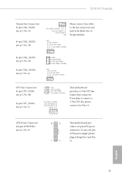
Z170 OC Formula Chassis Fan Connectors (4-pin CHA_FAN1) (see p.7, No. 13) (4-pin CHA_FAN2) (see p.7, No. 9) 12 24 1 13 his motherboard provides a 4-Pin CPU fan (Quiet Fan) ...(4-pin CPU_FAN2) (see p.7, No. 5) 1 GND 2 FAN_VOLTAGE 3 CPU_FAN_SPEED 4 FAN_SPEED_CONTROL FAN_SPEED_CONTROL CPU_FAN_SPEED FAN_VOLTAGE GND his motherboard provides a 24-pin ATX power connector. To use a 20-pin ATX power supply, please plug it to Pin 1-3. 1 2 34 ATX Power Connector (24-pin ATXPWR1) (see p.7, No. 38) FAN_SPEED_CONTROL CHA_FAN_SPEED FAN_VOLTAGE GND Please connect fan cables to the...
Z170 OC Formula Chassis Fan Connectors (4-pin CHA_FAN1) (see p.7, No. 13) (4-pin CHA_FAN2) (see p.7, No. 9) 12 24 1 13 his motherboard provides a 4-Pin CPU fan (Quiet Fan) ...(4-pin CPU_FAN2) (see p.7, No. 5) 1 GND 2 FAN_VOLTAGE 3 CPU_FAN_SPEED 4 FAN_SPEED_CONTROL FAN_SPEED_CONTROL CPU_FAN_SPEED FAN_VOLTAGE GND his motherboard provides a 24-pin ATX power connector. To use a 20-pin ATX power supply, please plug it to Pin 1-3. 1 2 34 ATX Power Connector (24-pin ATXPWR1) (see p.7, No. 38) FAN_SPEED_CONTROL CHA_FAN_SPEED FAN_VOLTAGE GND Please connect fan cables to the...
User Manual
Page 32
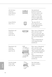
... card to the motherboard. RRXD1 DDTR#1 DDSR#1 CCTS#1 1 RRI#1 RRTS#1 GND TTXD1 DDCD#1 his motherboard provides an 8-pin ATX 12V power connector and 4 1 a 4-pin ATX 12V power connector. English ATX 12V Power Connectors (8-pin ATX12V1) (see p.7, No. 2) (4-pin ATX12V2) (see p.7, No. 1) hunderbolt 2 AIC Connector ...No. 40) 26 8 5 his COM1 header supports a serial port module. To use a 4-pin ATX power supply, please plug it along Pin 1 and Pin 5. *he 4-pin ATX 12V power connector is supported on this motherboard. DUMMY I2C_DATA I2C_CLOCK IRQ GND 1 GND SLP_S4# SLP_S3# ...
... card to the motherboard. RRXD1 DDTR#1 DDSR#1 CCTS#1 1 RRI#1 RRTS#1 GND TTXD1 DDCD#1 his motherboard provides an 8-pin ATX 12V power connector and 4 1 a 4-pin ATX 12V power connector. English ATX 12V Power Connectors (8-pin ATX12V1) (see p.7, No. 2) (4-pin ATX12V2) (see p.7, No. 1) hunderbolt 2 AIC Connector ...No. 40) 26 8 5 his COM1 header supports a serial port module. To use a 4-pin ATX power supply, please plug it along Pin 1 and Pin 5. *he 4-pin ATX 12V power connector is supported on this motherboard. DUMMY I2C_DATA I2C_CLOCK IRQ GND 1 GND SLP_S4# SLP_S3# ...