
User Manual
Page 7
... 3.1 Panel • 1 x SATA Express Cable • 1 x USB Power Cable 1 English In this documentation will be subject to change without further notice. ASRock website http://www.asrock.com. 1.1 Package Contents • ASRock Z170 Extreme7 Motherboard (ATX Form Factor) • ASRock Z170 Extreme7 Quick Installation Guide • ASRock Z170 Extreme7 Support CD • 4 x Serial ATA (SATA) Data Cables (Optional) • 1 x I/O Panel Shield •...
... 3.1 Panel • 1 x SATA Express Cable • 1 x USB Power Cable 1 English In this documentation will be subject to change without further notice. ASRock website http://www.asrock.com. 1.1 Package Contents • ASRock Z170 Extreme7 Motherboard (ATX Form Factor) • ASRock Z170 Extreme7 Quick Installation Guide • ASRock Z170 Extreme7 Support CD • 4 x Serial ATA (SATA) Data Cables (Optional) • 1 x I/O Panel Shield •...
User Manual
Page 9
... Video HD Technology, Intel® InsiderTM, Intel® HD Graphics 510/530 • Pixel Shader 5.0, DirectX 12 • Max. Z170 Extreme7+ Audio • Supports Intel® HD Graphics Built-in Visuals : Intel® Quick Sync Video with Diferential Ampliier - resolution up ...60Hz • Supports DisplayPort 1.2 with Content Protection (Realtek ALC1150 Audio Codec) • Premium Blu-ray Audio support • Supports Surge Protection (ASRock Full Spike Protection) • Supports Purity SoundTM 3 - resolution up to 4K x 2K (4096x2304) @ 24Hz • Supports DVI-D with max...
... Video HD Technology, Intel® InsiderTM, Intel® HD Graphics 510/530 • Pixel Shader 5.0, DirectX 12 • Max. Z170 Extreme7+ Audio • Supports Intel® HD Graphics Built-in Visuals : Intel® Quick Sync Video with Diferential Ampliier - resolution up ...60Hz • Supports DisplayPort 1.2 with Content Protection (Realtek ALC1150 Audio Codec) • Premium Blu-ray Audio support • Supports Surge Protection (ASRock Full Spike Protection) • Supports Purity SoundTM 3 - resolution up to 4K x 2K (4096x2304) @ 24Hz • Supports DVI-D with max...

User Manual
Page 11
... AIC Connector • 3 x USB 2.0 Headers (Support 6 USB 2.0 ports) (Supports ESD Protection (ASRock Full Spike Protection)) • 2 x USB 3.0 Headers (Support 4 USB 3.0 ports) (ASMedia ASM1074 hub) (Supports ESD Protection (ASRock Full Spike Protection)) • 1 x Dr. Debug with LED • 1 x Power Switch with ... • SMBIOS 2.3.1 Support • CPU, GT_CPU, DRAM, VPPM, PCH 1.0V, VCCIO, VC- Z170 Extreme7+ • 3 x SATA Express 10 Gb/s Connectors* * Support to Gen3 x4 (32 Gb/s) * Supports ASRock U.2 Kit Connector • 1 x COM Port Header • 1 x TPM Header • 1 ...
... AIC Connector • 3 x USB 2.0 Headers (Support 6 USB 2.0 ports) (Supports ESD Protection (ASRock Full Spike Protection)) • 2 x USB 3.0 Headers (Support 4 USB 3.0 ports) (ASMedia ASM1074 hub) (Supports ESD Protection (ASRock Full Spike Protection)) • 1 x Dr. Debug with LED • 1 x Power Switch with ... • SMBIOS 2.3.1 Support • CPU, GT_CPU, DRAM, VPPM, PCH 1.0V, VCCIO, VC- Z170 Extreme7+ • 3 x SATA Express 10 Gb/s Connectors* * Support to Gen3 x4 (32 Gb/s) * Supports ASRock U.2 Kit Connector • 1 x COM Port Header • 1 x TPM Header • 1 ...

User Manual
Page 17
English 11 Z170 Extreme7+ 1.5 ASRock Front USB 3.1 Panel Speciications Dimension • 75mm (W) x 42.8mm (H) x 148mm (L) Controller • ASMedia ASM1142 Controller Front Panel I/O • 1 x USB 3.1 Type-A Port (10 Gb/s) (Supports ESD Protection (ASRock Full Spike Protection)) * For charging Type-A USB devices, we suggest using... • 1 x USB 3.1 Type-C Port (10 Gb/s) (Supports ESD Protection (ASRock Full Spike Protection)) * his port supports power outputs up to install the ASRock Front USB 3.1 Panel into the drive bay of your chassis before connecting other USB devices....
English 11 Z170 Extreme7+ 1.5 ASRock Front USB 3.1 Panel Speciications Dimension • 75mm (W) x 42.8mm (H) x 148mm (L) Controller • ASMedia ASM1142 Controller Front Panel I/O • 1 x USB 3.1 Type-A Port (10 Gb/s) (Supports ESD Protection (ASRock Full Spike Protection)) * For charging Type-A USB devices, we suggest using... • 1 x USB 3.1 Type-C Port (10 Gb/s) (Supports ESD Protection (ASRock Full Spike Protection)) * his port supports power outputs up to install the ASRock Front USB 3.1 Panel into the drive bay of your chassis before connecting other USB devices....

User Manual
Page 19
USB3_4 USB3_4 13 SATA3_4_5 SATA3_A1_A2 SATA3_A3_A4 SATA_EXP0 SATA3_1_3 SATA3_0_2 Step 8 Connect the other end of the USB Power Cable to the SATA Express Connector on the motherboard. Step 7 Connect the other end of the SATA Express Cable to the USB 2.0 Header on the motherboard. USB 3.0 USB 3.0 English Z170 Extreme7+ Step 5 Screw ASRock Front USB 3.1 Panel to the SATA Power Connector. SATA3_4_5 SATA3_A1_A2 SATA3_A3_A4 SATA_EXP0 SATA3_1_3 SATA3_0_2 Step 6 Connect the PSU's SATA Power Cable to the drive bay with screws.
USB3_4 USB3_4 13 SATA3_4_5 SATA3_A1_A2 SATA3_A3_A4 SATA_EXP0 SATA3_1_3 SATA3_0_2 Step 8 Connect the other end of the USB Power Cable to the SATA Express Connector on the motherboard. Step 7 Connect the other end of the SATA Express Cable to the USB 2.0 Header on the motherboard. USB 3.0 USB 3.0 English Z170 Extreme7+ Step 5 Screw ASRock Front USB 3.1 Panel to the SATA Power Connector. SATA3_4_5 SATA3_A1_A2 SATA3_A3_A4 SATA_EXP0 SATA3_1_3 SATA3_0_2 Step 6 Connect the PSU's SATA Power Cable to the drive bay with screws.

User Manual
Page 51
Click to select "Auto run at Windows Startup" if you want A-Tuning to be launched when you start up the Windows operating system. 45 English Z170 Extreme7+ Settings Conigure ASRock A-Tuning.
Click to select "Auto run at Windows Startup" if you want A-Tuning to be launched when you start up the Windows operating system. 45 English Z170 Extreme7+ Settings Conigure ASRock A-Tuning.
User Manual
Page 57
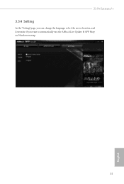
Z170 Extreme7+ 3.3.4 Setting In the "Setting" page, you can change the language, select the server location, and determine if you want to automatically run the ASRock Live Update & APP Shop on Windows startup. 51 English
Z170 Extreme7+ 3.3.4 Setting In the "Setting" page, you can change the language, select the server location, and determine if you want to automatically run the ASRock Live Update & APP Shop on Windows startup. 51 English
User Manual
Page 59
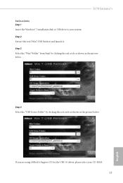
Step 4 Select the "USB Driver Folder" by clicking the red circle as shown as the picture below . If you are using ASRock's Support CD for the USB 3.0 driver, please select your system. Z170 Extreme7+ Instructions Step 1 Insert the Windows® 7 installation disk or USB drive to your CD-ROM. 53 English Step 2 Extract the tool (Win7 USB Patcher) and launch it. Step 3 Select the "Win7 Folder" from Step1 by clicking the red circle as shown as the picture below .
Step 4 Select the "USB Driver Folder" by clicking the red circle as shown as the picture below . If you are using ASRock's Support CD for the USB 3.0 driver, please select your system. Z170 Extreme7+ Instructions Step 1 Insert the Windows® 7 installation disk or USB drive to your CD-ROM. 53 English Step 2 Extract the tool (Win7 USB Patcher) and launch it. Step 3 Select the "Win7 Folder" from Step1 by clicking the red circle as shown as the picture below .


