

User Manual
Page 4
... Package Contents 1 1.2 Speciications 2 1.3 Motherboard Layout 7 1.4 I/O Panel 9 1.5 ASRock Front USB 3.1 Panel 11 Chapter 2 Installation 14 2.1 Installing the CPU 15 2.2 Installing the CPU Fan and Heatsink 18 2.3 Installing Memory Modules (DIMM) 19 2.4 Expansion Slots (PCI Express Slots) 21 2.5 Jumpers Setup 22 2.6 Onboard Headers and Connectors 23 2.7 Smart Switches 28 2.8 Dr. Debug 29 2.9 SLITM and Quad SLITM Operation Guide 31 2.9.1 Installing Two SLITM-Ready Graphics Cards 31 2.9.2 Driver Installation and Setup 33 2.10 CrossFireXTM, 3-Way CrossFireXTM and...
... Package Contents 1 1.2 Speciications 2 1.3 Motherboard Layout 7 1.4 I/O Panel 9 1.5 ASRock Front USB 3.1 Panel 11 Chapter 2 Installation 14 2.1 Installing the CPU 15 2.2 Installing the CPU Fan and Heatsink 18 2.3 Installing Memory Modules (DIMM) 19 2.4 Expansion Slots (PCI Express Slots) 21 2.5 Jumpers Setup 22 2.6 Onboard Headers and Connectors 23 2.7 Smart Switches 28 2.8 Dr. Debug 29 2.9 SLITM and Quad SLITM Operation Guide 31 2.9.1 Installing Two SLITM-Ready Graphics Cards 31 2.9.2 Driver Installation and Setup 33 2.10 CrossFireXTM, 3-Way CrossFireXTM and...

User Manual
Page 5
2.10.3 Driver Installation and Setup 37 2.11 M.2_SSD (NGFF) Module Installation Guide 38 Chapter 3 Software and Utilities Operation 41 3.1 Installing Drivers 41 3.2 A-Tuning 42 3.3 ASRock Live Update & APP Shop 46 3.3.1 UI Overview 46 3.3.2 Apps 47 3.3.3 BIOS & Drivers 50 3.3.4 Setting 51 3.4 Enabling USB Ports for Windows® 7 Installation 52 Chapter 4 UEFI SETUP UTILITY 55 4.1 Introduction 55 4.1.1 UEFI Menu Bar 55 4.1.2 Navigation Keys 56 4.2 Main Screen 57 4.3 OC Tweaker Screen 58 4.4 Advanced Screen 68 4.4.1 CPU Coniguration 69 4.4.2 Chipset ...
2.10.3 Driver Installation and Setup 37 2.11 M.2_SSD (NGFF) Module Installation Guide 38 Chapter 3 Software and Utilities Operation 41 3.1 Installing Drivers 41 3.2 A-Tuning 42 3.3 ASRock Live Update & APP Shop 46 3.3.1 UI Overview 46 3.3.2 Apps 47 3.3.3 BIOS & Drivers 50 3.3.4 Setting 51 3.4 Enabling USB Ports for Windows® 7 Installation 52 Chapter 4 UEFI SETUP UTILITY 55 4.1 Introduction 55 4.1.1 UEFI Menu Bar 55 4.1.2 Navigation Keys 56 4.2 Main Screen 57 4.3 OC Tweaker Screen 58 4.4 Advanced Screen 68 4.4.1 CPU Coniguration 69 4.4.2 Chipset ...
User Manual
Page 7
...(ATX Form Factor) • ASRock Z170 Extreme7 Quick Installation Guide • ASRock Z170 Extreme7 Support CD • 4 x Serial ATA (SATA) Data Cables (Optional) • 1 x I/O Panel Shield • 1 x ASRock SLI_Bridge_2S Card • 3 x Screw for M.2 Sockets • 1 x Screw for mini-PCIe Slot • 1 x ASRock Front USB 3.1 Panel • 4 x Screws for speciic information about the model you for purchasing ASRock Z170 Extreme7 motherboard, a reliable motherboard produced under ASRock's consistently stringent quality control. Z170 Extreme7+ Chapter 1 Introduction hank you are using...
...(ATX Form Factor) • ASRock Z170 Extreme7 Quick Installation Guide • ASRock Z170 Extreme7 Support CD • 4 x Serial ATA (SATA) Data Cables (Optional) • 1 x I/O Panel Shield • 1 x ASRock SLI_Bridge_2S Card • 3 x Screw for M.2 Sockets • 1 x Screw for mini-PCIe Slot • 1 x ASRock Front USB 3.1 Panel • 4 x Screws for speciic information about the model you for purchasing ASRock Z170 Extreme7 motherboard, a reliable motherboard produced under ASRock's consistently stringent quality control. Z170 Extreme7+ Chapter 1 Introduction hank you are using...

User Manual
Page 11
.../s) * Supports ASRock U.2 Kit Connector • 1 x COM Port Header • 1 x TPM Header • 1 x Power LED and Speaker Header • 2 x CPU Fan Connectors (4-pin) (Smart Fan Speed Control) • 4 x Chassis Fan Connectors (4-pin) (Smart Fan Speed Con- If either one of them is in use , the others will be announced * M2_1, SATA3_0, SATA3_1 and SATA_EXP0 share lanes. If either one of them is in use , the others will be disabled. * M2_2, SATA3_2, SATA3_3 and SATA_EXP1 share lanes. Z170 Extreme7+ • 3 x SATA Express 10 Gb/s Connectors* * Support...
.../s) * Supports ASRock U.2 Kit Connector • 1 x COM Port Header • 1 x TPM Header • 1 x Power LED and Speaker Header • 2 x CPU Fan Connectors (4-pin) (Smart Fan Speed Control) • 4 x Chassis Fan Connectors (4-pin) (Smart Fan Speed Con- If either one of them is in use , the others will be announced * M2_1, SATA3_0, SATA3_1 and SATA_EXP0 share lanes. If either one of them is in use , the others will be disabled. * M2_2, SATA3_2, SATA3_3 and SATA_EXP1 share lanes. Z170 Extreme7+ • 3 x SATA Express 10 Gb/s Connectors* * Support...

User Manual
Page 14
... SATA Express Connector (SATA_EXP0) 18 SATA Express Connector (SATA_EXP1) 19 SATA3 Connectors (SATA3_A3_A4) 20 SATA3 Connectors (SATA3_A1_A2) 21 SATA3 Connector (SATA3_4) 22 SATA3 Connector (SATA3_5) 23 SATA Express Connector (SATA_EXP2) 24 Power LED and Speaker Header (SPK_PLED1) 25 USB 2.0 Header (USB7_8) 26 USB 2.0 Header (USB5_6) 27 USB 2.0 Header (USB3_4) 28 System Panel Header (PANEL1) 29 BIOS Selection Switch (BIOS_SEL1) 30 Clear CMOS Jumper (CLRMOS1) 31 TPM Header (TPMS1) 32 COM Port Header (COM1) 33 Front Panel Audio Header (HD_AUDIO1) 34 hunderbolt AIC Connector (TB1) 35 Chassis Fan...
... SATA Express Connector (SATA_EXP0) 18 SATA Express Connector (SATA_EXP1) 19 SATA3 Connectors (SATA3_A3_A4) 20 SATA3 Connectors (SATA3_A1_A2) 21 SATA3 Connector (SATA3_4) 22 SATA3 Connector (SATA3_5) 23 SATA Express Connector (SATA_EXP2) 24 Power LED and Speaker Header (SPK_PLED1) 25 USB 2.0 Header (USB7_8) 26 USB 2.0 Header (USB5_6) 27 USB 2.0 Header (USB3_4) 28 System Panel Header (PANEL1) 29 BIOS Selection Switch (BIOS_SEL1) 30 Clear CMOS Jumper (CLRMOS1) 31 TPM Header (TPMS1) 32 COM Port Header (COM1) 33 Front Panel Audio Header (HD_AUDIO1) 34 hunderbolt AIC Connector (TB1) 35 Chassis Fan...

User Manual
Page 27
... connect a chassis fan to the motherboard's chassis fan connector (CHA_FAN1, CHA_FAN2, CHA_FAN3 or CHA_FAN4) when using multiple graphics cards. 21 PCIE6 (PCIe 3.0 x16 slot) is used for PCI Express x4 lane width graphics cards. Please read the documentation of the expansion card and make sure that the power supply is switched of or the power cord is used for WiFi module. mini-PCIe slot: MINI_PCIE1 (mini-PCIe slot) is used for the card before you start the installation. Before installing an expansion card...
... connect a chassis fan to the motherboard's chassis fan connector (CHA_FAN1, CHA_FAN2, CHA_FAN3 or CHA_FAN4) when using multiple graphics cards. 21 PCIE6 (PCIe 3.0 x16 slot) is used for PCI Express x4 lane width graphics cards. Please read the documentation of the expansion card and make sure that the power supply is switched of or the power cord is used for WiFi module. mini-PCIe slot: MINI_PCIE1 (mini-PCIe slot) is used for the card before you start the installation. Before installing an expansion card...

User Manual
Page 29
... sleep state or powered of power switch, reset switch, power LED, hard drive activity LED, speaker and etc. he LED is on when the system is on the chassis to the hard drive activity LED on the chassis front panel. he LED is operating. You may difer by chassis. Do NOT place jumper caps over the headers and connectors will cause permanent damage to perform a normal restart. Z170 Extreme7+ 2.6 Onboard Headers and Connectors Onboard headers and connectors are matched correctly. Press the reset switch...
... sleep state or powered of power switch, reset switch, power LED, hard drive activity LED, speaker and etc. he LED is on when the system is on the chassis to the hard drive activity LED on the chassis front panel. he LED is operating. You may difer by chassis. Do NOT place jumper caps over the headers and connectors will cause permanent damage to perform a normal restart. Z170 Extreme7+ 2.6 Onboard Headers and Connectors Onboard headers and connectors are matched correctly. Press the reset switch...

User Manual
Page 33
... LAD2 SMB_DATA_MAIN SMB_CLK_MAIN GN D +3VS B LAD0 +3V LAD3 PCIRST # FRAM E PCICLK 12 24 1 13 8 5 4 1 his COM1 header supports a serial port module. To use a 20-pin ATX power supply, please plug it along Pin 1 and Pin 13. his connector supports Trusted Platform Module (TPM) system, 1 which can securely store keys, digital certiicates, passwords, and data. GN D English 27 To use a 4-pin ATX power supply, please plug it along Pin 1 and Pin 5. his motherboard provides an 8-pin ATX 12V power connector.
... LAD2 SMB_DATA_MAIN SMB_CLK_MAIN GN D +3VS B LAD0 +3V LAD3 PCIRST # FRAM E PCICLK 12 24 1 13 8 5 4 1 his COM1 header supports a serial port module. To use a 20-pin ATX power supply, please plug it along Pin 1 and Pin 13. his connector supports Trusted Platform Module (TPM) system, 1 which can securely store keys, digital certiicates, passwords, and data. GN D English 27 To use a 4-pin ATX power supply, please plug it along Pin 1 and Pin 5. his motherboard provides an 8-pin ATX 12V power connector.
User Manual
Page 35
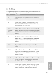
... codes. Please clear CMOS, re-install the memory and VGA card, and remove other USB, PCI devices. 01 - 54 (except 0d), 5A- 60 Problem related to memory. Please press reset or clear CMOS. 92 - 99 Problem related to IDE or SATA devices. Please re-install the memory and CPU. If the problem still exists, please clear CMOS and try removing all PCI-E devices or try using other memory modules. A7 Problem related to PCI-E devices. Z170 Extreme7+ 2.8 Dr. Debug Dr. Debug is installed correctly and then clear CMOS. 0d Problem...
... codes. Please clear CMOS, re-install the memory and VGA card, and remove other USB, PCI devices. 01 - 54 (except 0d), 5A- 60 Problem related to memory. Please press reset or clear CMOS. 92 - 99 Problem related to IDE or SATA devices. Please re-install the memory and CPU. If the problem still exists, please clear CMOS and try removing all PCI-E devices or try using other memory modules. A7 Problem related to PCI-E devices. Z170 Extreme7+ 2.8 Dr. Debug Dr. Debug is installed correctly and then clear CMOS. 0d Problem...

User Manual
Page 37
... identical PCI Express x16 graphics cards. Z170 Extreme7+ 2.9 SLITM and Quad SLITM Operation Guide his motherboard supports NVIDIA® SLITM and Quad SLITM (Scalable Link Interface) technology that your power supply unit (PSU) can provide at least the minimum power your graphics card driver supports NVIDIA® SLITM technology. Make sure that your system requires. Requirements 1. Please refer to the NVIDIA® website for details. 2.9.1 Installing Two SLITM-Ready Graphics Cards...
... identical PCI Express x16 graphics cards. Z170 Extreme7+ 2.9 SLITM and Quad SLITM Operation Guide his motherboard supports NVIDIA® SLITM and Quad SLITM (Scalable Link Interface) technology that your power supply unit (PSU) can provide at least the minimum power your graphics card driver supports NVIDIA® SLITM technology. Make sure that your system requires. Requirements 1. Please refer to the NVIDIA® website for details. 2.9.1 Installing Two SLITM-Ready Graphics Cards...

User Manual
Page 40
... your graphics card vendor for detailed installation guide. 2.10.1 Installing Two CrossFireXTM-Ready Graphics Cards Step 1 Insert one graphics card into PCIE2 slot and the other graphics card to three identical PCI Express x16 graphics cards. 1. Download the drivers from the AMD's website: www.amd.com 3. If you pair a 12-pipe CrossFireXTM Edition card with this motherboard. Diferent CrossFireXTM cards may require diferent methods to the AMD's website for details. 4. Make sure that your power supply...
... your graphics card vendor for detailed installation guide. 2.10.1 Installing Two CrossFireXTM-Ready Graphics Cards Step 1 Insert one graphics card into PCIE2 slot and the other graphics card to three identical PCI Express x16 graphics cards. 1. Download the drivers from the AMD's website: www.amd.com 3. If you pair a 12-pipe CrossFireXTM Edition card with this motherboard. Diferent CrossFireXTM cards may require diferent methods to the AMD's website for details. 4. Make sure that your power supply...
User Manual
Page 43
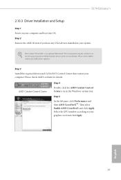
... We recommend using this utility to uninstall any VGA drivers installed in the Windows® system tray. Please check AMD's website for details. Step 3 Install the required drivers and CATALYST Control Center then restart your computer and boot into OS. hen select Enable AMD CrossFireX and click Apply. he Catalyst Uninstaller is an optional download. Step 2 Remove the AMD drivers if you have any previously installed Catalyst drivers prior to...
... We recommend using this utility to uninstall any VGA drivers installed in the Windows® system tray. Please check AMD's website for details. Step 3 Install the required drivers and CATALYST Control Center then restart your computer and boot into OS. hen select Enable AMD CrossFireX and click Apply. he Catalyst Uninstaller is an optional download. Step 2 Remove the AMD drivers if you have any previously installed Catalyst drivers prior to...
User Manual
Page 47
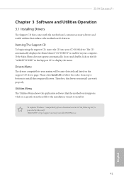
.... Z170 Extreme7+ Chapter 3 Software and Utilities Operation 3.1 Installing Drivers he Support CD that comes with the motherboard contains necessary drivers and useful utilities that the motherboard supports. If the Main Menu does not appear automatically, locate and double click on a speciic item then follow the order from top to bottom to install it. he drivers compatible to display the menu. Click on the ile "ASRSETUP.EXE" in your system will be auto...
.... Z170 Extreme7+ Chapter 3 Software and Utilities Operation 3.1 Installing Drivers he Support CD that comes with the motherboard contains necessary drivers and useful utilities that the motherboard supports. If the Main Menu does not appear automatically, locate and double click on a speciic item then follow the order from top to bottom to install it. he drivers compatible to display the menu. Click on the ile "ASRSETUP.EXE" in your system will be auto...

User Manual
Page 58
... Controller Interface (XHCI - USB3.0). You've got nothing: If you do not have an optical disc drive, please ind another computer and follow the instructions below and go ahead to install Windows® 7 OS. 3.4 Enabling USB Ports for Windows® 7 Installation Intel® Braswell and Skylake has removed their motherboard won't work. Please set PS/S Simulator back to install Windows 7 operating system because the USB ports on their support...
... Controller Interface (XHCI - USB3.0). You've got nothing: If you do not have an optical disc drive, please ind another computer and follow the instructions below and go ahead to install Windows® 7 OS. 3.4 Enabling USB Ports for Windows® 7 Installation Intel® Braswell and Skylake has removed their motherboard won't work. Please set PS/S Simulator back to install Windows 7 operating system because the USB ports on their support...
User Manual
Page 59
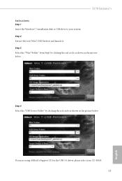
If you are using ASRock's Support CD for the USB 3.0 driver, please select your system. Step 2 Extract the tool (Win7 USB Patcher) and launch it. Z170 Extreme7+ Instructions Step 1 Insert the Windows® 7 installation disk or USB drive to your CD-ROM. 53 English Step 3 Select the "Win7 Folder" from Step1 by clicking the red circle as shown as the picture below . Step 4 Select the "USB Driver Folder" by clicking the red circle as shown as the picture below .
If you are using ASRock's Support CD for the USB 3.0 driver, please select your system. Step 2 Extract the tool (Win7 USB Patcher) and launch it. Z170 Extreme7+ Instructions Step 1 Insert the Windows® 7 installation disk or USB drive to your CD-ROM. 53 English Step 3 Select the "Win7 Folder" from Step1 by clicking the red circle as shown as the picture below . Step 4 Select the "USB Driver Folder" by clicking the red circle as shown as the picture below .

User Manual
Page 78
... enabled at all PCH PCIE devices. Front Panel Enable/disable front panel HD audio. IGPU Multi-Monitor Select disable to enable onboard HD audio and automatically disable it when a sound card is installed. Set to Auto to disable the integrated graphics when an external graphics card is installed. DMI ASPM Support his option enables/disables the ASPM support for lower power consumption. Onboard HD Audio Enable/disable onboard HD audio. WAN Radio Enable/disable the WiFi module's connectivity. Select enable to the integrated graphics processor when the system boots...
... enabled at all PCH PCIE devices. Front Panel Enable/disable front panel HD audio. IGPU Multi-Monitor Select disable to enable onboard HD audio and automatically disable it when a sound card is installed. Set to Auto to disable the integrated graphics when an external graphics card is installed. DMI ASPM Support his option enables/disables the ASPM support for lower power consumption. Onboard HD Audio Enable/disable onboard HD audio. WAN Radio Enable/disable the WiFi module's connectivity. Select enable to the integrated graphics processor when the system boots...

User Manual
Page 83
4.4.5 Super IO Coniguration Z170 Extreme7+ Serial Port Enable or disable the Serial port. Serial Port Address Select the address of the Serial port. PS2 Y-Cable Enable the PS2 Y-Cable or set this option to Auto. 77 English
4.4.5 Super IO Coniguration Z170 Extreme7+ Serial Port Enable or disable the Serial port. Serial Port Address Select the address of the Serial port. PS2 Y-Cable Enable the PS2 Y-Cable or set this option to Auto. 77 English
User Manual
Page 89
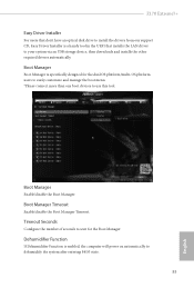
... the boot menu. *Please connect more than one boot devices to use this tool. Z170 Extreme7+ Easy Driver Installer For users that don't have an optical disk drive to install the drivers from our support CD, Easy Driver Installer is enabled, the computer will power on automatically to dehumidify the system ater entering S4/S5 state. 83 English Dehumidiier Function If Dehumidiier Function is a handy tool in the UEFI that installs the LAN driver to...
... the boot menu. *Please connect more than one boot devices to use this tool. Z170 Extreme7+ Easy Driver Installer For users that don't have an optical disk drive to install the drivers from our support CD, Easy Driver Installer is enabled, the computer will power on automatically to dehumidify the system ater entering S4/S5 state. 83 English Dehumidiier Function If Dehumidiier Function is a handy tool in the UEFI that installs the LAN driver to...

User Manual
Page 91
English 85 UEFI Download Server Select a server to conigure internet connection settings for Internet Flash. Z170 Extreme7+ Internet Setting Enable or disable sound efects in the setup utility. Network Coniguration Use this to download the UEFI irmware.
English 85 UEFI Download Server Select a server to conigure internet connection settings for Internet Flash. Z170 Extreme7+ Internet Setting Enable or disable sound efects in the setup utility. Network Coniguration Use this to download the UEFI irmware.

User Manual
Page 94
Supervisor Password Set or change the settings in the UEFI Setup Utility. Leave it blank and press enter to remove the password. Leave it blank and press enter to remove the password. Disable this item to change the password for Windows 8.1 Secure Boot. Users are unable to enable or disable support for the administrator account. Intel(R) Platform Trust Technology Enable/disable Intel PTT in the UEFI Setup Utility. Secure Boot Use this option to change the password for the system. Only the administrator has...
Supervisor Password Set or change the settings in the UEFI Setup Utility. Leave it blank and press enter to remove the password. Leave it blank and press enter to remove the password. Disable this item to change the password for Windows 8.1 Secure Boot. Users are unable to enable or disable support for the administrator account. Intel(R) Platform Trust Technology Enable/disable Intel PTT in the UEFI Setup Utility. Secure Boot Use this option to change the password for the system. Only the administrator has...


