
User Manual
Page 7
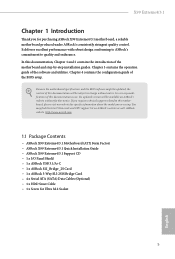
... without further notice. Chapter 3 contains the operation guide of the BIOS setup. ASRock website http://www.asrock.com. 1.1 Package Contents • ASRock X99 Extreme4/3.1 Motherboard (ATX Form Factor) • ASRock X99 Extreme4/3.1 Quick Installation Guide • ASRock X99 Extreme4/3.1 Support CD • 1 x I/O Panel Shield • 1 x ASRock USB 3.1/A+C • 1 x ASRock SLI_Bridge_2S Card • 1 x ASRock 3-Way SLI-2S1S Bridge Card • 4 x Serial ATA (SATA) Data Cables (Optional...
... without further notice. Chapter 3 contains the operation guide of the BIOS setup. ASRock website http://www.asrock.com. 1.1 Package Contents • ASRock X99 Extreme4/3.1 Motherboard (ATX Form Factor) • ASRock X99 Extreme4/3.1 Quick Installation Guide • ASRock X99 Extreme4/3.1 Support CD • 1 x I/O Panel Shield • 1 x ASRock USB 3.1/A+C • 1 x ASRock SLI_Bridge_2S Card • 1 x ASRock 3-Way SLI-2S1S Bridge Card • 4 x Serial ATA (SATA) Data Cables (Optional...
User Manual
Page 9
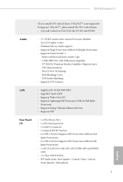
...Gigabit LAN 10/100/1000 Mb/s • Giga PHY Intel® I218V • Supports Wake-On-LAN • Supports Lightning/ESD Protection (ASRock Full Spike Protection) • Supports Energy Eicient Ethernet 802.3az • Supports PXE Rear Panel I/O • 1 x PS/2 Mouse Port ...x Optical SPDIF Out Port • 4 x USB 2.0 Ports (Supports ESD Protection (ASRock Full Spike Protection)) • 4 x USB 3.0 Ports (Supports ESD Protection (ASRock Full Spike Protection)) • 1 x RJ-45 LAN Port with 28 lanes, 3-Way SLITM is not supported. X99 Extreme4/3.1 * If you install CPU with LED (ACT...
...Gigabit LAN 10/100/1000 Mb/s • Giga PHY Intel® I218V • Supports Wake-On-LAN • Supports Lightning/ESD Protection (ASRock Full Spike Protection) • Supports Energy Eicient Ethernet 802.3az • Supports PXE Rear Panel I/O • 1 x PS/2 Mouse Port ...x Optical SPDIF Out Port • 4 x USB 2.0 Ports (Supports ESD Protection (ASRock Full Spike Protection)) • 4 x USB 3.0 Ports (Supports ESD Protection (ASRock Full Spike Protection)) • 1 x RJ-45 LAN Port with 28 lanes, 3-Way SLITM is not supported. X99 Extreme4/3.1 * If you install CPU with LED (ACT...
User Manual
Page 12
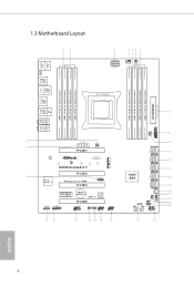
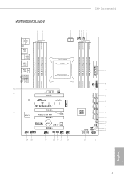
... 31 PWR_FAN1 PCIE1 M2_1 LAN Ultra M.2 PCIe Gen3 x4 CT5 CT4 CT3 CT2 CT1 X99 Extreme4/3.1 PCIE2 30 Purity SoundTM 2 PCI Express 3.0 RoHS PCIE3 1 T BT1 PCIE4 CMOS Battery Super USB 3.1 I/O PCIE5 HD_AUDIO1 1 1 TPMS1 COM1 1 CLRMOS1 BIOS_SEL1 1 1 1 USB6_7 ...USB4_5 1 29 28 27 26 25 24 23 CHA_FAN3 S_SATA3_0_1 S_SATA3_2_3 SATA3_0_3 SATA3_1_4 Intel X99 SATA3_2_5 SATAE_1 BIOS_A_LED CHA_FAN2 SATA_PWR_1 1 PLED1 CHA_FAN1 1...
... 31 PWR_FAN1 PCIE1 M2_1 LAN Ultra M.2 PCIe Gen3 x4 CT5 CT4 CT3 CT2 CT1 X99 Extreme4/3.1 PCIE2 30 Purity SoundTM 2 PCI Express 3.0 RoHS PCIE3 1 T BT1 PCIE4 CMOS Battery Super USB 3.1 I/O PCIE5 HD_AUDIO1 1 1 TPMS1 COM1 1 CLRMOS1 BIOS_SEL1 1 1 1 USB6_7 ...USB4_5 1 29 28 27 26 25 24 23 CHA_FAN3 S_SATA3_0_1 S_SATA3_2_3 SATA3_0_3 SATA3_1_4 Intel X99 SATA3_2_5 SATAE_1 BIOS_A_LED CHA_FAN2 SATA_PWR_1 1 PLED1 CHA_FAN1 1...
User Manual
Page 13
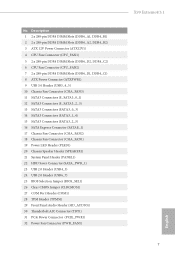
...Slots (DDR4_D2, DDR4_C2) 6 CPU Fan Connector (CPU_FAN2) 7 2 x 288-pin DDR4 DIMM Slots (DDR4_D1, DDR4_C1) 8 ATX Power Connector (ATXPWR1) 9 USB 3.0 Header (USB3_4_5) 10 Chassis Fan Connector (CHA_FAN3) 11 SATA3 Connectors (S_SATA3_0_1) 12 SATA3 Connectors (S_SATA3_2_3) 13 SATA3 Connectors (SATA3_0_3) 14 SATA3 Connectors (SATA3_1_4... Header (PLED1) 20 Chassis Speaker Header (SPEAKER1) 21 System Panel Header (PANEL1) 22 HDD Saver Connector (SATA_PWR_1) 23 USB 2.0 Header (USB4_5) 24 USB 2.0 Header (USB6_7) 25 BIOS Selection Jumper (BIOS_SEL1) 26 Clear CMOS Jumper (CLRCMOS1) 27 COM Port Header (COM1)...
...Slots (DDR4_D2, DDR4_C2) 6 CPU Fan Connector (CPU_FAN2) 7 2 x 288-pin DDR4 DIMM Slots (DDR4_D1, DDR4_C1) 8 ATX Power Connector (ATXPWR1) 9 USB 3.0 Header (USB3_4_5) 10 Chassis Fan Connector (CHA_FAN3) 11 SATA3 Connectors (S_SATA3_0_1) 12 SATA3 Connectors (S_SATA3_2_3) 13 SATA3 Connectors (SATA3_0_3) 14 SATA3 Connectors (SATA3_1_4... Header (PLED1) 20 Chassis Speaker Header (SPEAKER1) 21 System Panel Header (PANEL1) 22 HDD Saver Connector (SATA_PWR_1) 23 USB 2.0 Header (USB4_5) 24 USB 2.0 Header (USB6_7) 25 BIOS Selection Jumper (BIOS_SEL1) 26 Clear CMOS Jumper (CLRCMOS1) 27 COM Port Header (COM1)...

User Manual
Page 29
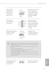
X99 Extreme4/3.1 USB 2.0 Headers (9-pin USB4_5) (see p.6, No. 23) (9-pin USB6_7) (see p.6, No. 24) USB_PWR PP+ GND DUMMY 1 GND P+ PUSB_PWR Besides four USB 2.0 ports on the I /O panel, there is for connecting audio devices to the front audio panel. 1. USB 3.0 Header (19-pin USB3_4_5) (see p.6, No. 9) Vbus ...don't need to the front panel audio header by the steps below: A. MIC_RET and OUT_RET are two headers on this motherboard. Each USB 2.0 header can support two ports. Front Panel Audio Header (9-pin HD_AUDIO1) (see p.6, No. 20) DUMMY SPEAKER 1 +5V DUMMY...
X99 Extreme4/3.1 USB 2.0 Headers (9-pin USB4_5) (see p.6, No. 23) (9-pin USB6_7) (see p.6, No. 24) USB_PWR PP+ GND DUMMY 1 GND P+ PUSB_PWR Besides four USB 2.0 ports on the I /O panel, there is for connecting audio devices to the front audio panel. 1. USB 3.0 Header (19-pin USB3_4_5) (see p.6, No. 9) Vbus ...don't need to the front panel audio header by the steps below: A. MIC_RET and OUT_RET are two headers on this motherboard. Each USB 2.0 header can support two ports. Front Panel Audio Header (9-pin HD_AUDIO1) (see p.6, No. 20) DUMMY SPEAKER 1 +5V DUMMY...
User Manual
Page 47
...the jumper cap placed on your PC for Windows® 7 (32-bit and 64-bit). 41 English Step 1 Power of ASRock USB 3.1/A+C, it is set to 10 Gbps. Detach all other cables that comes with your motherboard and remove its slot bracket. *To...slot on Pin1-2 (default) to install the ASRock USB 3.1/A+C. Step 4 Align the ASRock USB 3.1/A+C with the slot bracket's holding screw. Follow the simple steps below to Pin2-3. *Please install driver for details. X99 Extreme4/3.1 Installation Procedure he ASRock USB 3.1/A+C provides two external USB 3.1 ports which support transfer rates up to Pin1...
...the jumper cap placed on your PC for Windows® 7 (32-bit and 64-bit). 41 English Step 1 Power of ASRock USB 3.1/A+C, it is set to 10 Gbps. Detach all other cables that comes with your motherboard and remove its slot bracket. *To...slot on Pin1-2 (default) to install the ASRock USB 3.1/A+C. Step 4 Align the ASRock USB 3.1/A+C with the slot bracket's holding screw. Follow the simple steps below to Pin2-3. *Please install driver for details. X99 Extreme4/3.1 Installation Procedure he ASRock USB 3.1/A+C provides two external USB 3.1 ports which support transfer rates up to Pin1...
User Manual
Page 51
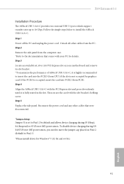
Enable this OC setting proile to the power supply connector. USB Key Plug in the USB Key and let your computer log in red color). OC DNA OC DNA is an unique sotware which helps to windows automatically! Click on hours, S.M.A.R.T. ... time until the computer powers on, and the duration of up and down the drive on and of the dehumidifying process. values, current temperature, etc. X99 Extreme4/3.1 FAN-Tastic Tuning Conigure up to dampness.
Enable this OC setting proile to the power supply connector. USB Key Plug in the USB Key and let your computer log in red color). OC DNA OC DNA is an unique sotware which helps to windows automatically! Click on hours, S.M.A.R.T. ... time until the computer powers on, and the duration of up and down the drive on and of the dehumidifying process. values, current temperature, etc. X99 Extreme4/3.1 FAN-Tastic Tuning Conigure up to dampness.
User Manual
Page 85
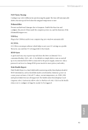
... issues it is recommended to disable legacy USB support. Intel USB 3.0 Mode Select Intel® USB 3.0 controller mode. If you encounter USB compatibility issues it is recommended to disable legacy USB support. Select UEFI Setup Only to support USB devices under Windows® 7). 4.4.6 USB Coniguration X99 Extreme4/3.1 USB Controller Enable or disable all the USB ports. Set [Enabled] to keep the...
... issues it is recommended to disable legacy USB support. Intel USB 3.0 Mode Select Intel® USB 3.0 controller mode. If you encounter USB compatibility issues it is recommended to disable legacy USB support. Select UEFI Setup Only to support USB devices under Windows® 7). 4.4.6 USB Coniguration X99 Extreme4/3.1 USB Controller Enable or disable all the USB ports. Set [Enabled] to keep the...
User Manual
Page 91
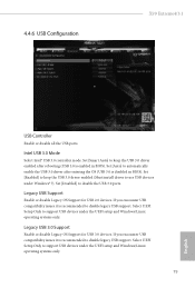
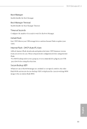
Secure Backup UEFI Whenever one of seconds to wait for you. X99 Extreme4/3.1 Boot Manager Enable/disable the Boot Manager. Internet Flash - DHCP (Auto IP), Auto ASRock Internet Flash downloads and updates the latest UEFI irmware version from our servers for the Boot Manager. Boot Manager Timeout Enable/disable the Boot Manager ... are outdated or corrupted, switch to the other lash ROM and execute Secure Backup UEFI to duplicate the current working ROM image to update your USB pen drive before using this function. Instant Flash Save UEFI iles in your UEFI.
Secure Backup UEFI Whenever one of seconds to wait for you. X99 Extreme4/3.1 Boot Manager Enable/disable the Boot Manager. Internet Flash - DHCP (Auto IP), Auto ASRock Internet Flash downloads and updates the latest UEFI irmware version from our servers for the Boot Manager. Boot Manager Timeout Enable/disable the Boot Manager ... are outdated or corrupted, switch to the other lash ROM and execute Secure Backup UEFI to duplicate the current working ROM image to update your USB pen drive before using this function. Instant Flash Save UEFI iles in your UEFI.
Quick Installation Guide
Page 3
Motherboard Layout 12 PS2 Mouse PS2 Keyboard CLRC BTN1 USB 2.0 T: USB0 B: USB1 USB 2.0 T: USB2 B: USB3 ESATA1 USB 3.0 T: USB0 B: USB1 USB 3.0 T: USB2 B: USB3 Top: RJ-45 X99 Extreme4/3.1 3 4 56 7 ATX12V1 CPU_FAN1 CPU_FAN2 2011-3 Socket 8 DDR4_D2 (64 bit, 288-pin module) DDR4_D1 (64...32 PCIE_PWR1 31 PWR_FAN1 PCIE1 M2_1 LAN Ultra M.2 PCIe Gen3 x4 CT5 CT4 CT3 CT2 CT1 X99 Extreme4/3.1 PCIE2 30 Purity SoundTM 2 PCI Express 3.0 RoHS PCIE3 1 T BT1 PCIE4 CMOS Battery Super USB 3.1 I/O PCIE5 HD_AUDIO1 1 1 TPMS1 COM1 1 CLRMOS1 BIOS_SEL1 1 1 1 USB6_7 USB4_5 1 ...
Motherboard Layout 12 PS2 Mouse PS2 Keyboard CLRC BTN1 USB 2.0 T: USB0 B: USB1 USB 2.0 T: USB2 B: USB3 ESATA1 USB 3.0 T: USB0 B: USB1 USB 3.0 T: USB2 B: USB3 Top: RJ-45 X99 Extreme4/3.1 3 4 56 7 ATX12V1 CPU_FAN1 CPU_FAN2 2011-3 Socket 8 DDR4_D2 (64 bit, 288-pin module) DDR4_D1 (64...32 PCIE_PWR1 31 PWR_FAN1 PCIE1 M2_1 LAN Ultra M.2 PCIe Gen3 x4 CT5 CT4 CT3 CT2 CT1 X99 Extreme4/3.1 PCIE2 30 Purity SoundTM 2 PCI Express 3.0 RoHS PCIE3 1 T BT1 PCIE4 CMOS Battery Super USB 3.1 I/O PCIE5 HD_AUDIO1 1 1 TPMS1 COM1 1 CLRMOS1 BIOS_SEL1 1 1 1 USB6_7 USB4_5 1 ...
Quick Installation Guide
Page 7
... related to this motherboard, please visit our website for Ultra M.2 Socket 5 English ASRock website http://www.asrock.com. 1.1 Package Contents • ASRock X99 Extreme4/3.1 Motherboard (ATX Form Factor) • ASRock X99 Extreme4/3.1 Quick Installation Guide • ASRock X99 Extreme4/3.1 Support CD • 1 x I/O Panel Shield • 1 x ASRock USB 3.1/A+C • 1 x ASRock SLI_Bridge_2S Card • 1 x ASRock 3-Way SLI-2S1S Bridge Card • 4 x Serial ATA (SATA) Data Cables (Optional...
... related to this motherboard, please visit our website for Ultra M.2 Socket 5 English ASRock website http://www.asrock.com. 1.1 Package Contents • ASRock X99 Extreme4/3.1 Motherboard (ATX Form Factor) • ASRock X99 Extreme4/3.1 Quick Installation Guide • ASRock X99 Extreme4/3.1 Support CD • 1 x I/O Panel Shield • 1 x ASRock USB 3.1/A+C • 1 x ASRock SLI_Bridge_2S Card • 1 x ASRock 3-Way SLI-2S1S Bridge Card • 4 x Serial ATA (SATA) Data Cables (Optional...

Quick Installation Guide
Page 9
...SNR DAC with Content Protection (Realtek ALC1150 Audio Codec) • Premium Blu-ray Audio support • Supports Surge Protection (ASRock Full Spike Protection) • Supports Purity Sound™ 2 - EMI Shielding Cover - PCB Isolate Shielding • Supports ...SPDIF Out Port • 4 x USB 2.0 Ports (Supports ESD Protection (ASRock Full Spike Protection)) • 4 x USB 3.0 Ports (Supports ESD Protection (ASRock Full Spike Protection)) • 1 x RJ-45 LAN Port with 28 lanes, 3-Way SLITM is not supported. Direct Drive Technology - X99 Extreme4/3.1 * If you install CPU with...
...SNR DAC with Content Protection (Realtek ALC1150 Audio Codec) • Premium Blu-ray Audio support • Supports Surge Protection (ASRock Full Spike Protection) • Supports Purity Sound™ 2 - EMI Shielding Cover - PCB Isolate Shielding • Supports ...SPDIF Out Port • 4 x USB 2.0 Ports (Supports ESD Protection (ASRock Full Spike Protection)) • 4 x USB 3.0 Ports (Supports ESD Protection (ASRock Full Spike Protection)) • 1 x RJ-45 LAN Port with 28 lanes, 3-Way SLITM is not supported. Direct Drive Technology - X99 Extreme4/3.1 * If you install CPU with...
Quick Installation Guide
Page 25
... panel and adjust "Recording Volume". To activate the front mic, go to the front panel audio header by the steps below: A. Each USB 2.0 header can support two ports. B. X99 Extreme4/3.1 USB 2.0 Headers (9-pin USB4_5) (see p.1, No. 23) (9-pin USB6_7) (see p.1, No. 24) USB_PWR PP+ GND DUMMY 1 GND P+... PUSB_PWR Besides four USB 2.0 ports on the I /O panel, there is for the HD audio panel only. If you use an AC'97 audio panel,...
... panel and adjust "Recording Volume". To activate the front mic, go to the front panel audio header by the steps below: A. Each USB 2.0 header can support two ports. B. X99 Extreme4/3.1 USB 2.0 Headers (9-pin USB4_5) (see p.1, No. 23) (9-pin USB6_7) (see p.1, No. 24) USB_PWR PP+ GND DUMMY 1 GND P+... PUSB_PWR Besides four USB 2.0 ports on the I /O panel, there is for the HD audio panel only. If you use an AC'97 audio panel,...
Quick Installation Guide
Page 33
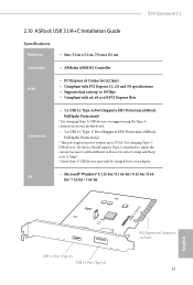
X99 Extreme4/3.1 2.10 ASRock USB 3.1/A+C Installation Guide Speciications Platform • Size: 3.1-in x 3.2-in, 7.9 cm x 8.1 cm Controller • ASMedia ASM1142 Controller PCIE • PCI Express x4 Connector (x2 lane) &#... x4, x8 or x16 PCI Express Slots Connector • 1 x USB 3.1 Type-A Port (Supports ESD Protection (ASRock Full Spike Protection)) * For charging Type-A USB devices, we suggest using the Type-A connectors on your motherboard. • 1 x USB 3.1 Type-C Port (Supports ESD Protection (ASRock Full Spike Protection)) * his port supports power outputs up to adjust ...
X99 Extreme4/3.1 2.10 ASRock USB 3.1/A+C Installation Guide Speciications Platform • Size: 3.1-in x 3.2-in, 7.9 cm x 8.1 cm Controller • ASMedia ASM1142 Controller PCIE • PCI Express x4 Connector (x2 lane) &#... x4, x8 or x16 PCI Express Slots Connector • 1 x USB 3.1 Type-A Port (Supports ESD Protection (ASRock Full Spike Protection)) * For charging Type-A USB devices, we suggest using the Type-A connectors on your motherboard. • 1 x USB 3.1 Type-C Port (Supports ESD Protection (ASRock Full Spike Protection)) * his port supports power outputs up to adjust ...
Quick Installation Guide
Page 129
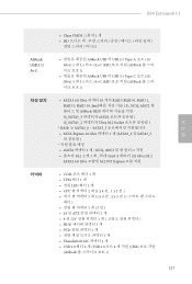
X99 Extreme4/3.1 한국어 ASRock USB 3.1/ A+C 커넥터 • Clear CMOS 스위치 1 개 • HD ASRock USB 의 USB 3.1 Type-A 포트 (10 Gb/s) 1 개 3.1 카드 /A+C (ESD ASRock ASRock USB 의 USB 3.1 Type-C 포트 (10 Gb/s) 1 개 3.1 카드 /A+C (ESD ASRock • SATA3 6.0 Gb/s 커넥터 10 개가 RAID (RAID 0, RAID 1, RAID 5, RAID 10, Intel...
X99 Extreme4/3.1 한국어 ASRock USB 3.1/ A+C 커넥터 • Clear CMOS 스위치 1 개 • HD ASRock USB 의 USB 3.1 Type-A 포트 (10 Gb/s) 1 개 3.1 카드 /A+C (ESD ASRock ASRock USB 의 USB 3.1 Type-C 포트 (10 Gb/s) 1 개 3.1 카드 /A+C (ESD ASRock • SATA3 6.0 Gb/s 커넥터 10 개가 RAID (RAID 0, RAID 1, RAID 5, RAID 10, Intel...
Quick Installation Guide
Page 141
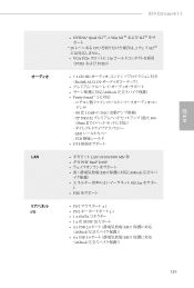
...;αϙʔ τ • PXE Λαϙʔτ • PS/2 x 1 • PS/2 x 1 • 1 x eSATA 1 x ޫ SPDIF 4 x USB 2.0 ESD ʢASRock 4 x USB 3.0 ESD ʢASRock 139 日本語 X99 Extreme4/3.1 ΦʔσΟΦ LAN ϦΞύωϧ I/O • NVIDIA® Quad SLITMɺ3-Way SLITM ͓Α...3 ΣΠ SLITM VGA PCIe εϩοτʹ 15 PCIE1 ͓Αͼ PCIE3ʣ • 7.1 CH HD Realtek ALC1150 ASRock Purity Sound ™ 2 ʹରԠ -
...;αϙʔ τ • PXE Λαϙʔτ • PS/2 x 1 • PS/2 x 1 • 1 x eSATA 1 x ޫ SPDIF 4 x USB 2.0 ESD ʢASRock 4 x USB 3.0 ESD ʢASRock 139 日本語 X99 Extreme4/3.1 ΦʔσΟΦ LAN ϦΞύωϧ I/O • NVIDIA® Quad SLITMɺ3-Way SLITM ͓Α...3 ΣΠ SLITM VGA PCIe εϩοτʹ 15 PCIE1 ͓Αͼ PCIE3ʣ • 7.1 CH HD Realtek ALC1150 ASRock Purity Sound ™ 2 ʹରԠ -


