
User Manual
Page 4
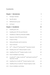
... Package Contents 1 1.2 Speciications 2 1.3 Motherboard Layout 6 1.4 I/O Panel 8 Chapter 2 Installation 10 2.1 Installing the CPU 11 2.2 Installing the CPU Fan and Heatsink 14 2.3 Installation of Memory Modules (DIMM) 15 2.4 Expansion Slots (PCI Express Slots) 17 2.5 Jumpers Setup 19 2.6 Onboard Headers and Connectors 21 2.7 Smart Switches 26 2.8 SLITM , 3-Way SLITMand Quad SLITM Operation Guide 27 2.8.1 Installing Two SLITM-Ready Graphics Cards 27 2.8.2 Installing Three SLITM-Ready Graphics Cards 29 2.8.3 Driver Installation and Setup 31 2.9 CrossFireXTM, 3-Way...
... Package Contents 1 1.2 Speciications 2 1.3 Motherboard Layout 6 1.4 I/O Panel 8 Chapter 2 Installation 10 2.1 Installing the CPU 11 2.2 Installing the CPU Fan and Heatsink 14 2.3 Installation of Memory Modules (DIMM) 15 2.4 Expansion Slots (PCI Express Slots) 17 2.5 Jumpers Setup 19 2.6 Onboard Headers and Connectors 21 2.7 Smart Switches 26 2.8 SLITM , 3-Way SLITMand Quad SLITM Operation Guide 27 2.8.1 Installing Two SLITM-Ready Graphics Cards 27 2.8.2 Installing Three SLITM-Ready Graphics Cards 29 2.8.3 Driver Installation and Setup 31 2.9 CrossFireXTM, 3-Way...
User Manual
Page 7
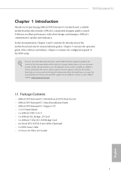
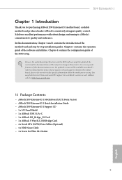
...; ASRock X99 Extreme4/3.1 Quick Installation Guide • ASRock X99 Extreme4/3.1 Support CD • 1 x I/O Panel Shield • 1 x ASRock USB 3.1/A+C • 1 x ASRock SLI_Bridge_2S Card • 1 x ASRock 3-Way SLI-2S1S Bridge Card • 4 x Serial ATA (SATA) Data Cables (Optional) • 1 x HDD Saver Cable • 1 x Screw for purchasing ASRock X99 Extreme4/3.1 motherboard, a reliable motherboard produced under ASRock's consistently stringent quality control. X99 Extreme4/3.1 Chapter 1 Introduction hank you are using. Chapter 3 contains the operation guide of the BIOS setup...
...; ASRock X99 Extreme4/3.1 Quick Installation Guide • ASRock X99 Extreme4/3.1 Support CD • 1 x I/O Panel Shield • 1 x ASRock USB 3.1/A+C • 1 x ASRock SLI_Bridge_2S Card • 1 x ASRock 3-Way SLI-2S1S Bridge Card • 4 x Serial ATA (SATA) Data Cables (Optional) • 1 x HDD Saver Cable • 1 x Screw for purchasing ASRock X99 Extreme4/3.1 motherboard, a reliable motherboard produced under ASRock's consistently stringent quality control. X99 Extreme4/3.1 Chapter 1 Introduction hank you are using. Chapter 3 contains the operation guide of the BIOS setup...
User Manual
Page 10
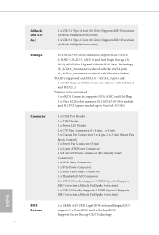
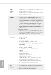
... PCI Express module up to Gen3 x4 (32 Gb/s) Connector • 1 x COM Port Header • 1 x TPM Header • 1 x Power LED Header • 2 x CPU Fan Connectors (1 x 4-pin, 1 x 3-pin) • 3 x Chassis Fan Connectors (1 x 4-pin, 2 x 3-pin) (Smart Fan Speed Control) • 1 x Power Fan Connector (3-pin) • 1 x 24 pin ATX Power Connector • 1 x 8 pin 12V Power Connector (Hi-Density Power Connector) • 1 x HDD Saver Connector • 1 x PCIe Power Connector • 1 x Front Panel Audio Connector • 1 x hunderbolt AIC Connector • 2 x USB 2.0 Headers (support...
... PCI Express module up to Gen3 x4 (32 Gb/s) Connector • 1 x COM Port Header • 1 x TPM Header • 1 x Power LED Header • 2 x CPU Fan Connectors (1 x 4-pin, 1 x 3-pin) • 3 x Chassis Fan Connectors (1 x 4-pin, 2 x 3-pin) (Smart Fan Speed Control) • 1 x Power Fan Connector (3-pin) • 1 x 24 pin ATX Power Connector • 1 x 8 pin 12V Power Connector (Hi-Density Power Connector) • 1 x HDD Saver Connector • 1 x PCIe Power Connector • 1 x Front Panel Audio Connector • 1 x hunderbolt AIC Connector • 2 x USB 2.0 Headers (support...
User Manual
Page 13
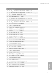
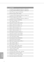
... SATA3 Connectors (SATA3_2_5) 16 SATA Express Connector (SATAE_1) 17 Chassis Fan Connector (CHA_FAN2) 18 Chassis Fan Connector (CHA_FAN1) 19 Power LED Header (PLED1) 20 Chassis Speaker Header (SPEAKER1) 21 System Panel Header (PANEL1) 22 HDD Saver Connector (SATA_PWR_1) 23 USB 2.0 Header (USB4_5) 24 USB 2.0 Header (USB6_7) 25 BIOS Selection Jumper (BIOS_SEL1) 26 Clear CMOS Jumper (CLRCMOS1) 27 COM Port Header (COM1) 28 TPM Header (TPMS1) 29 Front Panel Audio Header (HD_AUDIO1) 30 hunderbolt AIC Connector (TBT1) 31 PCIe Power Connector (PCIE_PWR1) 32 Power Fan Connector (PWR_FAN1) X99 Extreme4...
... SATA3 Connectors (SATA3_2_5) 16 SATA Express Connector (SATAE_1) 17 Chassis Fan Connector (CHA_FAN2) 18 Chassis Fan Connector (CHA_FAN1) 19 Power LED Header (PLED1) 20 Chassis Speaker Header (SPEAKER1) 21 System Panel Header (PANEL1) 22 HDD Saver Connector (SATA_PWR_1) 23 USB 2.0 Header (USB4_5) 24 USB 2.0 Header (USB6_7) 25 BIOS Selection Jumper (BIOS_SEL1) 26 Clear CMOS Jumper (CLRCMOS1) 27 COM Port Header (COM1) 28 TPM Header (TPMS1) 29 Front Panel Audio Header (HD_AUDIO1) 30 hunderbolt AIC Connector (TBT1) 31 PCIe Power Connector (PCIE_PWR1) 32 Power Fan Connector (PWR_FAN1) X99 Extreme4...
User Manual
Page 31
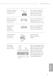
... securely store keys, digital certiicates, passwords, and data. TPM Header (17-pin TPMS1) (see p.6, No. 27) Please connect the HDD Saver 1 Cable to this connector to manage the power state of HDD. HDD Saver Connector (4-pin SATA_PWR_1) (see p.6, No. 22) hunderbolt AIC Connector (5-pin TBT1) (see p.6, No. 30) Serial Port Header (9-pin COM1) (see p.6, No. 28) 1 GN D SMB_CLK_MAIN SMB_DATA_MAIN LAD2 LAD1 GN D S_PWRDWN # SERIRQ # GND his COM1 header supports a serial port module. X99 Extreme4/3.1 PCIe Power Connector (4-pin PCIE_PWR1...
... securely store keys, digital certiicates, passwords, and data. TPM Header (17-pin TPMS1) (see p.6, No. 27) Please connect the HDD Saver 1 Cable to this connector to manage the power state of HDD. HDD Saver Connector (4-pin SATA_PWR_1) (see p.6, No. 22) hunderbolt AIC Connector (5-pin TBT1) (see p.6, No. 30) Serial Port Header (9-pin COM1) (see p.6, No. 28) 1 GN D SMB_CLK_MAIN SMB_DATA_MAIN LAD2 LAD1 GN D S_PWRDWN # SERIRQ # GND his COM1 header supports a serial port module. X99 Extreme4/3.1 PCIe Power Connector (4-pin PCIE_PWR1...
User Manual
Page 38
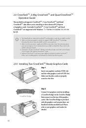
... PCI Express x16 graphics cards. Make sure that are properly seated on the top of the graphics cards. (he CrossFire Bridge is provided with the graphics card you purchase, not bundled with this motherboard. Please refer to the AMD's website for detailed installation guide. 2.9.1 Installing Two CrossFireXTM-Ready Graphics Cards Step 1 Insert one graphics card into PCIE1 slot and the other graphics card to your graphics card driver supports AMD CrossFireXTM technology. Please refer to PCIE3 slot...
... PCI Express x16 graphics cards. Make sure that are properly seated on the top of the graphics cards. (he CrossFire Bridge is provided with the graphics card you purchase, not bundled with this motherboard. Please refer to the AMD's website for detailed installation guide. 2.9.1 Installing Two CrossFireXTM-Ready Graphics Cards Step 1 Insert one graphics card into PCIE1 slot and the other graphics card to your graphics card driver supports AMD CrossFireXTM technology. Please refer to PCIE3 slot...
User Manual
Page 41
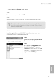
... computer and boot into OS. Please check AMD's website for details. Select the GPU number according to installation. Please check AMD's website for AMD driver updates. English 35 We recommend using this utility to uninstall any VGA drivers installed in the Windows® system tray. AMD Catalyst Control Center Step 4 Double-click the AMD Catalyst Control Center icon in your graphics card and click Apply. hen select Enable AMD CrossFireX and...
... computer and boot into OS. Please check AMD's website for details. Select the GPU number according to installation. Please check AMD's website for AMD driver updates. English 35 We recommend using this utility to uninstall any VGA drivers installed in the Windows® system tray. AMD Catalyst Control Center Step 4 Double-click the AMD Catalyst Control Center icon in your graphics card and click Apply. hen select Enable AMD CrossFireX and...
User Manual
Page 45
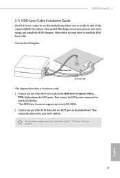
X99 Extreme4/3.1 2.11 HDD Saver Cable Installation Guide The HDD Saver Connector on this user manual. 39 English hen connect the SATA power connector(s) to your SATA HDD(s). Connect one end of the SATA data cable to your SATA HDD(s). * he diagram shown here is for reference only. 1. his design secures more privacy, saves more energy, and extends the HDDs' lifespans. Please follow the steps below to switch on the motherboard. hen connect the other end to...
X99 Extreme4/3.1 2.11 HDD Saver Cable Installation Guide The HDD Saver Connector on this user manual. 39 English hen connect the SATA power connector(s) to your SATA HDD(s). Connect one end of the SATA data cable to your SATA HDD(s). * he diagram shown here is for reference only. 1. his design secures more privacy, saves more energy, and extends the HDDs' lifespans. Please follow the steps below to switch on the motherboard. hen connect the other end to...
User Manual
Page 47
...-bit). 41 English Step 5 Replace the side panel. Step 1 Power of ASRock USB 3.1/A+C, it is highly recommended to Pin2-3. *Please install driver for details. Step 3 Locate an available x4, x8 or x16 PCI Express slot on Pin1-2 (default) to insert the card into PCIE2 (from PCH). Step 2 Remove the side panel from the computer case. *Refer to Pin1-2 by graphics card. To disable device charging during S3 (Sleep), S4 (Suspend) or S5 (Power Of) power...
...-bit). 41 English Step 5 Replace the side panel. Step 1 Power of ASRock USB 3.1/A+C, it is highly recommended to Pin2-3. *Please install driver for details. Step 3 Locate an available x4, x8 or x16 PCI Express slot on Pin1-2 (default) to insert the card into PCIE2 (from PCH). Step 2 Remove the side panel from the computer case. *Refer to Pin1-2 by graphics card. To disable device charging during S3 (Sleep), S4 (Suspend) or S5 (Power Of) power...

User Manual
Page 48
... to bottom to install it. Drivers Menu he drivers compatible to display the menu. he Utilities Menu shows the application sotware that enhance the motherboard's features. herefore, the drivers you install can work properly. Chapter 3 Software and Utilities Operation 3.1 Installing Drivers he Support CD that comes with the motherboard contains necessary drivers and useful utilities that the motherboard supports. Utilities Menu he CD automatically displays the Main Menu if "AUTORUN" is enabled in the Support CD to your CD-ROM drive. Click on...
... to bottom to install it. Drivers Menu he drivers compatible to display the menu. he Utilities Menu shows the application sotware that enhance the motherboard's features. herefore, the drivers you install can work properly. Chapter 3 Software and Utilities Operation 3.1 Installing Drivers he Support CD that comes with the motherboard contains necessary drivers and useful utilities that the motherboard supports. Utilities Menu he CD automatically displays the Main Menu if "AUTORUN" is enabled in the Support CD to your CD-ROM drive. Click on...
User Manual
Page 80
... is installed. Onboard HD Audio Enable/disable onboard HD audio. PCIE5 Link Speed Select the link speed for PCIE2. Onboard LAN Enable or disable the onboard network interface controller. Intel® Smart Connect Technology Intel® Smart Connect Technology automatically updates your email and social networks, such as Twitter, Facebook, etc. Set to Auto to enable onboard HD audio and automatically disable it when a sound card is in sleep mode. Deep Sleep Conigure deep sleep mode for all PCH downstream devices PCH DMI ASPM Support his option enables/disables the...
... is installed. Onboard HD Audio Enable/disable onboard HD audio. PCIE5 Link Speed Select the link speed for PCIE2. Onboard LAN Enable or disable the onboard network interface controller. Intel® Smart Connect Technology Intel® Smart Connect Technology automatically updates your email and social networks, such as Twitter, Facebook, etc. Set to Auto to enable onboard HD audio and automatically disable it when a sound card is in sleep mode. Deep Sleep Conigure deep sleep mode for all PCH downstream devices PCH DMI ASPM Support his option enables/disables the...
User Manual
Page 85
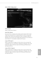
...or disable Legacy OS Support for USB 2.0 devices. If you encounter USB compatibility issues it is enabled in BIOS). Set [Disabled] to support USB devices under the UEFI setup and Windows/Linux operating systems only. 79 English 4.4.6 USB Coniguration X99 Extreme4/3.1 USB Controller Enable or disable all the USB ports. Legacy USB Support Enable or disable Legacy OS Support for USB 3.0 devices. Set [Smart Auto] to keep the USB 3.0 driver enabled (Must install driver to disable legacy USB support. Select UEFI Setup Only to disable the USB 3.0 ports. Intel USB 3.0 Mode...
...or disable Legacy OS Support for USB 2.0 devices. If you encounter USB compatibility issues it is enabled in BIOS). Set [Disabled] to support USB devices under the UEFI setup and Windows/Linux operating systems only. 79 English 4.4.6 USB Coniguration X99 Extreme4/3.1 USB Controller Enable or disable all the USB ports. Legacy USB Support Enable or disable Legacy OS Support for USB 3.0 devices. Set [Smart Auto] to keep the USB 3.0 driver enabled (Must install driver to disable legacy USB support. Select UEFI Setup Only to disable the USB 3.0 ports. Intel USB 3.0 Mode...
User Manual
Page 90
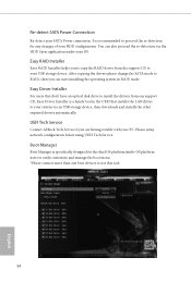
... USB storage device. UEFI Tech Service Contact ASRock Tech Service if you can also proceed the re-detection via an USB storage device, then downloads and installs the other required drivers automatically. Ater copying the drivers please change the SATA mode to copy the RAID driver from our support CD, Easy Driver Installer is speciically designed for any changes of your system via the HDD Saver application under your SATA Power connection. Easy Driver Installer For users that installs the LAN driver to use...
... USB storage device. UEFI Tech Service Contact ASRock Tech Service if you can also proceed the re-detection via an USB storage device, then downloads and installs the other required drivers automatically. Ater copying the drivers please change the SATA mode to copy the RAID driver from our support CD, Easy Driver Installer is speciically designed for any changes of your system via the HDD Saver application under your SATA Power connection. Easy Driver Installer For users that installs the LAN driver to use...
User Manual
Page 92
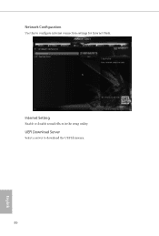
UEFI Download Server Select a server to conigure internet connection settings for Internet Flash. Network Coniguration Use this to download the UEFI irmware. 86 English Internet Setting Enable or disable sound efects in the setup utility.
UEFI Download Server Select a server to conigure internet connection settings for Internet Flash. Network Coniguration Use this to download the UEFI irmware. 86 English Internet Setting Enable or disable sound efects in the setup utility.
Quick Installation Guide
Page 4
... 15 SATA3 Connectors (SATA3_2_5) 16 SATA Express Connector (SATAE_1) 17 Chassis Fan Connector (CHA_FAN2) 18 Chassis Fan Connector (CHA_FAN1) 19 Power LED Header (PLED1) 20 Chassis Speaker Header (SPEAKER1) 21 System Panel Header (PANEL1) 22 HDD Saver Connector (SATA_PWR_1) 23 USB 2.0 Header (USB4_5) 24 USB 2.0 Header (USB6_7) 25 BIOS Selection Jumper (BIOS_SEL1) 26 Clear CMOS Jumper (CLRCMOS1) 27 COM Port Header (COM1) 28 TPM Header (TPMS1) 29 Front Panel Audio Header (HD_AUDIO1) 30 hunderbolt AIC Connector (TBT1) 31 PCIe Power Connector (PCIE_PWR1) 32 Power Fan Connector (PWR_FAN1) 2 English...
... 15 SATA3 Connectors (SATA3_2_5) 16 SATA Express Connector (SATAE_1) 17 Chassis Fan Connector (CHA_FAN2) 18 Chassis Fan Connector (CHA_FAN1) 19 Power LED Header (PLED1) 20 Chassis Speaker Header (SPEAKER1) 21 System Panel Header (PANEL1) 22 HDD Saver Connector (SATA_PWR_1) 23 USB 2.0 Header (USB4_5) 24 USB 2.0 Header (USB6_7) 25 BIOS Selection Jumper (BIOS_SEL1) 26 Clear CMOS Jumper (CLRCMOS1) 27 COM Port Header (COM1) 28 TPM Header (TPMS1) 29 Front Panel Audio Header (HD_AUDIO1) 30 hunderbolt AIC Connector (TBT1) 31 PCIe Power Connector (PCIE_PWR1) 32 Power Fan Connector (PWR_FAN1) 2 English...
Quick Installation Guide
Page 7
...purchasing ASRock X99 Extreme4/3.1 motherboard, a reliable motherboard produced under ASRock's consistently stringent quality control. If you are using. ASRock website http://www.asrock.com. 1.1 Package Contents • ASRock X99 Extreme4/3.1 Motherboard (ATX Form Factor) • ASRock X99 Extreme4/3.1 Quick Installation Guide • ASRock X99 Extreme4/3.1 Support CD • 1 x I/O Panel Shield • 1 x ASRock USB 3.1/A+C • 1 x ASRock SLI_Bridge_2S Card • 1 x ASRock 3-Way SLI-2S1S Bridge Card • 4 x Serial ATA (SATA) Data Cables (Optional) • 1 x HDD Saver Cable...
...purchasing ASRock X99 Extreme4/3.1 motherboard, a reliable motherboard produced under ASRock's consistently stringent quality control. If you are using. ASRock website http://www.asrock.com. 1.1 Package Contents • ASRock X99 Extreme4/3.1 Motherboard (ATX Form Factor) • ASRock X99 Extreme4/3.1 Quick Installation Guide • ASRock X99 Extreme4/3.1 Support CD • 1 x I/O Panel Shield • 1 x ASRock USB 3.1/A+C • 1 x ASRock SLI_Bridge_2S Card • 1 x ASRock 3-Way SLI-2S1S Bridge Card • 4 x Serial ATA (SATA) Data Cables (Optional) • 1 x HDD Saver Cable...
Quick Installation Guide
Page 10
... PCI Express module up to Gen3 x4 (32 Gb/s) Connector • 1 x COM Port Header • 1 x TPM Header • 1 x Power LED Header • 2 x CPU Fan Connectors (1 x 4-pin, 1 x 3-pin) • 3 x Chassis Fan Connectors (1 x 4-pin, 2 x 3-pin) (Smart Fan Speed Control) • 1 x Power Fan Connector (3-pin) • 1 x 24 pin ATX Power Connector • 1 x 8 pin 12V Power Connector (Hi-Density Power Connector) • 1 x HDD Saver Connector • 1 x PCIe Power Connector • 1 x Front Panel Audio Connector • 1 x hunderbolt AIC Connector • 2 x USB 2.0 Headers (support...
... PCI Express module up to Gen3 x4 (32 Gb/s) Connector • 1 x COM Port Header • 1 x TPM Header • 1 x Power LED Header • 2 x CPU Fan Connectors (1 x 4-pin, 1 x 3-pin) • 3 x Chassis Fan Connectors (1 x 4-pin, 2 x 3-pin) (Smart Fan Speed Control) • 1 x Power Fan Connector (3-pin) • 1 x 24 pin ATX Power Connector • 1 x 8 pin 12V Power Connector (Hi-Density Power Connector) • 1 x HDD Saver Connector • 1 x PCIe Power Connector • 1 x Front Panel Audio Connector • 1 x hunderbolt AIC Connector • 2 x USB 2.0 Headers (support...
Quick Installation Guide
Page 32
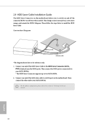
... only. 1. Connection Diagram 1 HDD Saver Cable 2 SATA data cable *he HDD Saver Connector supports up to the section 3.2 "A-Tuning" in the user manual. 30 English hen connect the other end to a SATA port on and off the connected HDDs via sotware when needed. For the sotware coniguration, please refer to two SATA HDDs. 2. hen connect the SATA power connector(s) to your SATA HDD(s). 2.9 HDD Saver Cable Installation Guide The HDD Saver Connector on this motherboard allows you to switch on the motherboard. his...
... only. 1. Connection Diagram 1 HDD Saver Cable 2 SATA data cable *he HDD Saver Connector supports up to the section 3.2 "A-Tuning" in the user manual. 30 English hen connect the other end to a SATA port on and off the connected HDDs via sotware when needed. For the sotware coniguration, please refer to two SATA HDDs. 2. hen connect the SATA power connector(s) to your SATA HDD(s). 2.9 HDD Saver Cable Installation Guide The HDD Saver Connector on this motherboard allows you to switch on the motherboard. his...

RAID Installation Guide
Page 7
... 64-bit / 8 / 8 64-bit / 7 / 7 64-bit OS on your USB storage device with RAID functions, please follow the procedures below. Boot your system. 7 STEP 2: Use ASRock Easy RAID Installer Easy RAID Installer can copy the RAID driver from a support CD to enter BIOS setup utility. C. Press [Enter] to complete the process. 2.3 Installing Windows® 8.1 / 8.1 64-bit / 8 / 8 64-bit / 7 / 7 64-bit With RAID Functions If you exit BIOS setup. Press key to save your change before setting your USB lash drive into a USB port. Enter UEFI SETUP UTILITY Tool and highlight "Easy RAID...
... 64-bit / 8 / 8 64-bit / 7 / 7 64-bit OS on your USB storage device with RAID functions, please follow the procedures below. Boot your system. 7 STEP 2: Use ASRock Easy RAID Installer Easy RAID Installer can copy the RAID driver from a support CD to enter BIOS setup utility. C. Press [Enter] to complete the process. 2.3 Installing Windows® 8.1 / 8.1 64-bit / 8 / 8 64-bit / 7 / 7 64-bit With RAID Functions If you exit BIOS setup. Press key to save your change before setting your USB lash drive into a USB port. Enter UEFI SETUP UTILITY Tool and highlight "Easy RAID...
RAID Installation Guide
Page 18
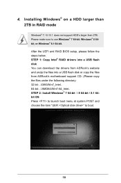
... launch boot menu at system POST and choose the item "UEFI:" to use Windows® 7 64-bit, Windows® 8 64bit, or Windows® 8.1 64-bit. After the UEFI and RAID BIOS setup, please follow the steps below. 4. Please make sure to boot. 18 STEP 1: Copy Intel® RAID drivers into a USB lash disk You can download the drivers from ASRock's website and unzip the iles into a USB lash disk or copy the iles from ASRock's motherboard support...
... launch boot menu at system POST and choose the item "UEFI:" to use Windows® 7 64-bit, Windows® 8 64bit, or Windows® 8.1 64-bit. After the UEFI and RAID BIOS setup, please follow the steps below. 4. Please make sure to boot. 18 STEP 1: Copy Intel® RAID drivers into a USB lash disk You can download the drivers from ASRock's website and unzip the iles into a USB lash disk or copy the iles from ASRock's motherboard support...


