

User Manual
Page 26
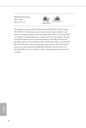
... the BIOS LED (BIOS_A_LED or BIOS_B_LED) to identify which enhances protection for the safety and stability of system safety, users cannot update the backup BIOS manually. However, if the main BIOS is activated currently. BIOS Selection Jumper (BIOS_SEL1) (see p.6, No. 25) Default Backup BIOS (Main BIOS) his motherboard has two BIOS...
... the BIOS LED (BIOS_A_LED or BIOS_B_LED) to identify which enhances protection for the safety and stability of system safety, users cannot update the backup BIOS manually. However, if the main BIOS is activated currently. BIOS Selection Jumper (BIOS_SEL1) (see p.6, No. 25) Default Backup BIOS (Main BIOS) his motherboard has two BIOS...

User Manual
Page 29
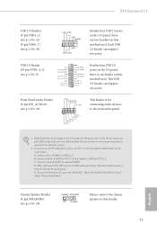
.... Connect Audio_R (RIN) to OUT2_R and Audio_L (LIN) to Ground (GND). D. E. his header is one header on this motherboard. Connect Ground (GND) to OUT2_L. X99 Extreme4/3.1 USB 2.0 Headers (9-pin USB4_5) (see p.6, No. 23) (9-pin USB6_7) (see p.6, No. 24) USB_PWR PP+ GND DUMMY 1 GND P+ PUSB_PWR Besides four USB...for the HD audio panel only. If you use an AC'97 audio panel, please install it to the "FrontMic" Tab in our manual and chassis manual to the front audio panel. 1. C. Chassis Speaker Header (4-pin SPEAKER1) (see p.6, No. 29) GND PRESENCE# MIC_RET OUT_RET 1 O...
.... Connect Audio_R (RIN) to OUT2_R and Audio_L (LIN) to Ground (GND). D. E. his header is one header on this motherboard. Connect Ground (GND) to OUT2_L. X99 Extreme4/3.1 USB 2.0 Headers (9-pin USB4_5) (see p.6, No. 23) (9-pin USB6_7) (see p.6, No. 24) USB_PWR PP+ GND DUMMY 1 GND P+ PUSB_PWR Besides four USB...for the HD audio panel only. If you use an AC'97 audio panel, please install it to the "FrontMic" Tab in our manual and chassis manual to the front audio panel. 1. C. Chassis Speaker Header (4-pin SPEAKER1) (see p.6, No. 29) GND PRESENCE# MIC_RET OUT_RET 1 O...
User Manual
Page 38
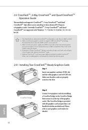
... (PSU) can provide at least the minimum power your system requires. Make sure that the cards are AMD certiied. 2. Please refer to AMD graphics card manuals for detailed installation guide. 2.9.1 Installing Two CrossFireXTM-Ready Graphics Cards Step 1 Insert one graphics card into PCIE1 slot and the other graphics card to enable...
... (PSU) can provide at least the minimum power your system requires. Make sure that the cards are AMD certiied. 2. Please refer to AMD graphics card manuals for detailed installation guide. 2.9.1 Installing Two CrossFireXTM-Ready Graphics Cards Step 1 Insert one graphics card into PCIE1 slot and the other graphics card to enable...
User Manual
Page 45
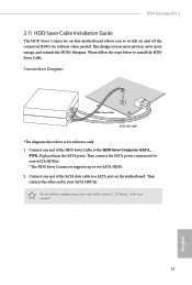
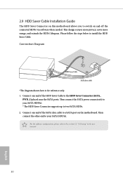
... you to the HDD Saver Connector (SATA_ PWR_1) placed near the SATA ports. Connect one end of the SATA data cable to your SATA HDD(s). X99 Extreme4/3.1 2.11 HDD Saver Cable Installation Guide The HDD Saver Connector on this user manual. 39 English
... you to the HDD Saver Connector (SATA_ PWR_1) placed near the SATA ports. Connect one end of the SATA data cable to your SATA HDD(s). X99 Extreme4/3.1 2.11 HDD Saver Cable Installation Guide The HDD Saver Connector on this user manual. 39 English
User Manual
Page 73
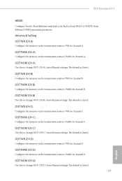
...termination resistors' WR for channel D. ODT NOM (CH C) Use this to change ODT (CH C) Auto/Manual settings. ODT NOM (CH D) Use this to change ODT (CH A) Auto/Manual settings. X99 Extreme4/3.1 tRRDR Conigure Read to Read diferent rank dead cycle Back to back READ to change ODT (CH D) ...Auto/Manual settings. ODT WR (CH C) Conigure the memory on die termination resistors' WR for channel C. ODT...
...termination resistors' WR for channel D. ODT NOM (CH C) Use this to change ODT (CH C) Auto/Manual settings. ODT NOM (CH D) Use this to change ODT (CH A) Auto/Manual settings. X99 Extreme4/3.1 tRRDR Conigure Read to Read diferent rank dead cycle Back to back READ to change ODT (CH D) ...Auto/Manual settings. ODT WR (CH C) Conigure the memory on die termination resistors' WR for channel C. ODT...
Quick Installation Guide
Page 22
... the BIOS LED (BIOS_A_LED or BIOS_B_LED) to identify which enhances protection for the safety and stability of system safety, users cannot update the backup BIOS manually. Ater that, short pin1 and pin2 again, then use a jumper cap to short pin2 and pin3, then the backup BIOS will take over on the...
... the BIOS LED (BIOS_A_LED or BIOS_B_LED) to identify which enhances protection for the safety and stability of system safety, users cannot update the backup BIOS manually. Ater that, short pin1 and pin2 again, then use a jumper cap to short pin2 and pin3, then the backup BIOS will take over on the...
Quick Installation Guide
Page 25
... (4-pin SPEAKER1) (see p.1, No. 20) DUMMY SPEAKER 1 +5V DUMMY Please connect the chassis speaker to the "FrontMic" Tab in our manual and chassis manual to install your system. 2. Front Panel Audio Header (9-pin HD_AUDIO1) (see p.1, No. 29) GND PRESENCE# MIC_RET OUT_RET 1 O UT2 _L... there are for the HD audio panel only. B. C. Connect Mic_IN (MIC) to connect them for the AC'97 audio panel. You don't need to MIC2_L. X99 Extreme4/3.1 USB 2.0 Headers (9-pin USB4_5) (see p.1, No. 23) (9-pin USB6_7) (see p.1, No. 24) USB_PWR PP+ GND DUMMY 1 GND P+ PUSB_PWR Besides four...
... (4-pin SPEAKER1) (see p.1, No. 20) DUMMY SPEAKER 1 +5V DUMMY Please connect the chassis speaker to the "FrontMic" Tab in our manual and chassis manual to install your system. 2. Front Panel Audio Header (9-pin HD_AUDIO1) (see p.1, No. 29) GND PRESENCE# MIC_RET OUT_RET 1 O UT2 _L... there are for the HD audio panel only. B. C. Connect Mic_IN (MIC) to connect them for the AC'97 audio panel. You don't need to MIC2_L. X99 Extreme4/3.1 USB 2.0 Headers (9-pin USB4_5) (see p.1, No. 23) (9-pin USB6_7) (see p.1, No. 24) USB_PWR PP+ GND DUMMY 1 GND P+ PUSB_PWR Besides four...
Quick Installation Guide
Page 32
... HDD(s). For the sotware coniguration, please refer to install the HDD Saver Cable. Please follow the steps below to the section 3.2 "A-Tuning" in the user manual. 30 English Connect one end of the SATA data cable to a SATA port on and off the connected HDDs via sotware when needed. 2.9 HDD Saver...
... HDD(s). For the sotware coniguration, please refer to install the HDD Saver Cable. Please follow the steps below to the section 3.2 "A-Tuning" in the user manual. 30 English Connect one end of the SATA data cable to a SATA port on and off the connected HDDs via sotware when needed. 2.9 HDD Saver...
