

User Manual
Page 10
...BIOS Selection Switch English 10 Connector • 1 x COM Port Header • 1 x Power LED Header • 2 x CPU Fan Connectors (1 x 4-pin, 1 x 3-pin) • 3 x Chassis Fan Connectors (1 x 4-pin, 2 x 3-pin) (Smart Fan Speed Control) • 1 x Power Fan Connector (3-pin) • 1 x SB Fan Connector (3-pin) • 1 x 24 pin ATX Power Connector • 1 x 8 pin 12V Power Connector (Hi-Density Power Connector) • 1 x HDD Saver Connector • 2 x PCIe Power Connectors • 1 x Front Panel Audio Connector • 2 x USB 2.0 Headers (support 4 USB 2.0 ports) (Supports...
...BIOS Selection Switch English 10 Connector • 1 x COM Port Header • 1 x Power LED Header • 2 x CPU Fan Connectors (1 x 4-pin, 1 x 3-pin) • 3 x Chassis Fan Connectors (1 x 4-pin, 2 x 3-pin) (Smart Fan Speed Control) • 1 x Power Fan Connector (3-pin) • 1 x SB Fan Connector (3-pin) • 1 x 24 pin ATX Power Connector • 1 x 8 pin 12V Power Connector (Hi-Density Power Connector) • 1 x HDD Saver Connector • 2 x PCIe Power Connectors • 1 x Front Panel Audio Connector • 2 x USB 2.0 Headers (support 4 USB 2.0 ports) (Supports...

User Manual
Page 13
... SATA3 Connectors (SATA3_2_5) 17 SAS Connectors (SAS_0_1) 18 SAS Connectors (SAS_2_3) 19 SAS Connectors (SAS_4_5) 20 SAS Connectors (SAS_6_7) 21 Chassis Speaker Header (SPEAKER1) 22 SB Fan Connector (SB_FAN1) 23 HDD Saver Connector (SATA_PWR_1) 24 Power LED Header (PLED1) 25 System Panel Header (PANEL1) 26 Power Switch (PWRBTN1) 27 Reset Switch (RSTBTN1) 28 BIOS Selection Switch (BIOS_SEL1) 29 Chassis Fan Connector (CHA_FAN1) 30 Chassis Fan Connector (CHA_FAN2) 31 USB 2.0 Header (USB4_5) 32 USB 2.0 Header (USB6_7) 33 COM Port Header (COM1) 34 PCIe Power Connector (PCIE_PWR2) X99 Extreme11 13...
... SATA3 Connectors (SATA3_2_5) 17 SAS Connectors (SAS_0_1) 18 SAS Connectors (SAS_2_3) 19 SAS Connectors (SAS_4_5) 20 SAS Connectors (SAS_6_7) 21 Chassis Speaker Header (SPEAKER1) 22 SB Fan Connector (SB_FAN1) 23 HDD Saver Connector (SATA_PWR_1) 24 Power LED Header (PLED1) 25 System Panel Header (PANEL1) 26 Power Switch (PWRBTN1) 27 Reset Switch (RSTBTN1) 28 BIOS Selection Switch (BIOS_SEL1) 29 Chassis Fan Connector (CHA_FAN1) 30 Chassis Fan Connector (CHA_FAN2) 31 USB 2.0 Header (USB4_5) 32 USB 2.0 Header (USB6_7) 33 COM Port Header (COM1) 34 PCIe Power Connector (PCIE_PWR2) X99 Extreme11 13...

User Manual
Page 27
For connecting SAS HDDs, please contact SAS data cable dealers. *It is supported on SATA3_0 ~ SATA3_5 ports only. hese eight SAS-3 connectors support SAS/ SATA data cables for internal storage devices with up to 12.0 Gb/s data transfer rate. he current SAS-3 interface allows up to the SAS-3 connectors. 27 English If the eSATA port (ESATA2) on the rear I /O has been connected, the internal S_SATA3_1 will not...
For connecting SAS HDDs, please contact SAS data cable dealers. *It is supported on SATA3_0 ~ SATA3_5 ports only. hese eight SAS-3 connectors support SAS/ SATA data cables for internal storage devices with up to 12.0 Gb/s data transfer rate. he current SAS-3 interface allows up to the SAS-3 connectors. 27 English If the eSATA port (ESATA2) on the rear I /O has been connected, the internal S_SATA3_1 will not...

User Manual
Page 32
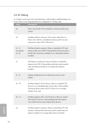
... reset or clear CMOS. 92 - 99 Problem related to memory. Please re-install the CPU and memory. A0 - Please re-install IDE and SATA devices. Please clear CMOS, re-install the memory and VGA card, and remove other USB, PCIE devices. 01 - 54 (except 0d), 5A- 60 Problem related to PCI-E devices. Please re-install the memory and CPU. English 32 If the problem still exists, please install only one memory module or try installing them in other memory modules. 61 - 91 Chipset initialization error. Code...
... reset or clear CMOS. 92 - 99 Problem related to memory. Please re-install the CPU and memory. A0 - Please re-install IDE and SATA devices. Please clear CMOS, re-install the memory and VGA card, and remove other USB, PCIE devices. 01 - 54 (except 0d), 5A- 60 Problem related to PCI-E devices. Please re-install the memory and CPU. English 32 If the problem still exists, please install only one memory module or try installing them in other memory modules. 61 - 91 Chipset initialization error. Code...

User Manual
Page 41
... card with Windows® 7 / 7 64-bit / 8 / 8 64-bit / 8.1 / 8.1 64-bit OS. 1. Make sure that your power supply unit (PSU) can provide at least the minimum power your graphics card vendor for details. 4. X99 Extreme11 2.10 CrossFireXTM, 3-Way CrossFireXTM, 4-Way CrossFireXTM and Quad CrossFireXTM Operation Guide his motherboard supports CrossFireXTM, 3-way CrossFireXTM, 4-way CrossFireXTM and Quad CrossFireXTM that allows you to install up to use identical CrossFireXTM-ready graphics cards...
... card with Windows® 7 / 7 64-bit / 8 / 8 64-bit / 8.1 / 8.1 64-bit OS. 1. Make sure that your power supply unit (PSU) can provide at least the minimum power your graphics card vendor for details. 4. X99 Extreme11 2.10 CrossFireXTM, 3-Way CrossFireXTM, 4-Way CrossFireXTM and Quad CrossFireXTM Operation Guide his motherboard supports CrossFireXTM, 3-way CrossFireXTM, 4-way CrossFireXTM and Quad CrossFireXTM that allows you to install up to use identical CrossFireXTM-ready graphics cards...
User Manual
Page 45
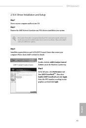
... then AMD CrossFireXTM. Please check AMD's website for details. We recommend using this utility to uninstall any VGA drivers installed in the Windows® system tray. Step 2 Remove the AMD drivers if you have any previously installed Catalyst drivers prior to your computer. Please check AMD's website for AMD driver updates. English 45 he Catalyst Uninstaller is an optional download. X99 Extreme11 2.10.4 Driver Installation and Setup Step 1 Power on your system. hen select Enable AMD CrossFireX...
... then AMD CrossFireXTM. Please check AMD's website for details. We recommend using this utility to uninstall any VGA drivers installed in the Windows® system tray. Step 2 Remove the AMD drivers if you have any previously installed Catalyst drivers prior to your computer. Please check AMD's website for AMD driver updates. English 45 he Catalyst Uninstaller is an optional download. X99 Extreme11 2.10.4 Driver Installation and Setup Step 1 Power on your system. hen select Enable AMD CrossFireX...
User Manual
Page 51
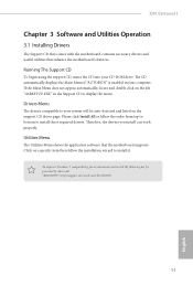
.... he CD automatically displays the Main Menu if "AUTORUN" is enabled in the Support CD to your CD-ROM drive. "KB2720599": http://support.microsot.com/kb/2720599 51 English Click on the support CD driver page. Please click Install All or follow the installation wizard to install those required drivers. X99 Extreme11 Chapter 3 Software and Utilities Operation 3.1 Installing Drivers he Support CD that comes with the motherboard contains necessary drivers and useful utilities that the motherboard supports.
.... he CD automatically displays the Main Menu if "AUTORUN" is enabled in the Support CD to your CD-ROM drive. "KB2720599": http://support.microsot.com/kb/2720599 51 English Click on the support CD driver page. Please click Install All or follow the installation wizard to install those required drivers. X99 Extreme11 Chapter 3 Software and Utilities Operation 3.1 Installing Drivers he Support CD that comes with the motherboard contains necessary drivers and useful utilities that the motherboard supports.

User Manual
Page 87
... for USB 2.0 devices. Set [Smart Auto] to keep the USB 3.0 driver enabled (Must install driver to support USB devices under the UEFI setup and Windows/Linux operating systems only. 87 English Set [Disabled] to support USB devices under Windows® 7). Intel USB 3.0 Mode Select Intel® USB 3.0 controller mode. 4.4.6 USB Coniguration X99 Extreme11 USB Controller Enable or disable all the USB ports. Select UEFI Setup Only to disable the USB 3.0 ports. If you encounter USB compatibility issues it is enabled in BIOS). Select UEFI Setup Only to use USB devices under...
... for USB 2.0 devices. Set [Smart Auto] to keep the USB 3.0 driver enabled (Must install driver to support USB devices under the UEFI setup and Windows/Linux operating systems only. 87 English Set [Disabled] to support USB devices under Windows® 7). Intel USB 3.0 Mode Select Intel® USB 3.0 controller mode. 4.4.6 USB Coniguration X99 Extreme11 USB Controller Enable or disable all the USB ports. Select UEFI Setup Only to disable the USB 3.0 ports. If you encounter USB compatibility issues it is enabled in BIOS). Select UEFI Setup Only to use USB devices under...
User Manual
Page 90
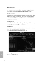
... in the UEFI that don't have an optical disk drive to install the drivers from the support CD to your USB storage device. Boot Manager Enable/disable the Boot Manager. 90 English Easy Driver Installer For users that installs the LAN driver to RAID, then you are having trouble with your system via an USB storage device, then downloads and installs the other required drivers automatically. Please setup network coniguration before using UEFI Tech Service. Ater copying the drivers please change the SATA mode to your...
... in the UEFI that don't have an optical disk drive to install the drivers from the support CD to your USB storage device. Boot Manager Enable/disable the Boot Manager. 90 English Easy Driver Installer For users that installs the LAN driver to RAID, then you are having trouble with your system via an USB storage device, then downloads and installs the other required drivers automatically. Please setup network coniguration before using UEFI Tech Service. Ater copying the drivers please change the SATA mode to your...
Quick Installation Guide
Page 11
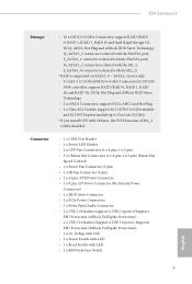
..., support RAID (RAID 0, RAID 1, RAID 1E and RAID 10), NCQ, Hot Plug and ASRock HDD Saver Technology • 2 x eSATA Connectors, support NCQ, AHCI and Hot Plug • 2 x Ultra M.2 Sockets, support M.2 SATA3 6.0 Gb/s module and M.2 PCI Express module up to Gen3 x4 (32 Gb/s) * If you install CPU with LED • 1 x BIOS Selection Switch 9 English Connector • 1 x COM Port Header • 1 x Power LED Header • 2 x CPU Fan Connectors (1 x 4-pin, 1 x 3-pin) • 3 x Chassis Fan Connectors (1 x 4-pin, 2 x 3-pin) (Smart Fan Speed Control) • 1 x Power Fan Connector (3-pin...
..., support RAID (RAID 0, RAID 1, RAID 1E and RAID 10), NCQ, Hot Plug and ASRock HDD Saver Technology • 2 x eSATA Connectors, support NCQ, AHCI and Hot Plug • 2 x Ultra M.2 Sockets, support M.2 SATA3 6.0 Gb/s module and M.2 PCI Express module up to Gen3 x4 (32 Gb/s) * If you install CPU with LED • 1 x BIOS Selection Switch 9 English Connector • 1 x COM Port Header • 1 x Power LED Header • 2 x CPU Fan Connectors (1 x 4-pin, 1 x 3-pin) • 3 x Chassis Fan Connectors (1 x 4-pin, 2 x 3-pin) (Smart Fan Speed Control) • 1 x Power Fan Connector (3-pin...

Quick Installation Guide
Page 23
Serial ATA3 Connectors (S_SATA3_0_1: see p.1, No. 12) (S_SATA3_2_3: see p.1, No. 13) (SATA3_0_3: see p.1, No. 14) (SATA3_1_4: see p.1, No. 15) (SATA3_2_5: see p.1, No. 16) SAS-3 Connectors (SAS_0_1: see p.1, No. 17) (SAS_2_3: see p.1,...X99 Extreme11 hese ten SATA3 connectors support SATA data cables for internal storage devices. If the eSATA port (ESATA2) on the rear I /O has been connected, the internal S_SATA3_1 will not function. If the Ultra M.2 Socket (M2_1) has been occupied, the internal S_SATA3_2 will not function. * RAID is not recommended to connnect DVD-ROM to the SAS-3 connectors...
Serial ATA3 Connectors (S_SATA3_0_1: see p.1, No. 12) (S_SATA3_2_3: see p.1, No. 13) (SATA3_0_3: see p.1, No. 14) (SATA3_1_4: see p.1, No. 15) (SATA3_2_5: see p.1, No. 16) SAS-3 Connectors (SAS_0_1: see p.1, No. 17) (SAS_2_3: see p.1,...X99 Extreme11 hese ten SATA3 connectors support SATA data cables for internal storage devices. If the eSATA port (ESATA2) on the rear I /O has been connected, the internal S_SATA3_1 will not function. If the Ultra M.2 Socket (M2_1) has been occupied, the internal S_SATA3_2 will not function. * RAID is not recommended to connnect DVD-ROM to the SAS-3 connectors...

Quick Installation Guide
Page 26
...his motherboard provides an 8-pin ATX 12V power connector. HDD Saver Connector (4-pin SATA_PWR_1) (see p.1, No. 23) Serial Port Header (9-pin COM1) (see p.1, No. 34) 8 5 4 1 GND +12V DETECT his COM1 header supports a serial port module. To use a 4-pin ATX power supply, please plug it along Pin 1 and Pin 5. English 24 Please connect a 4 pin molex power cable to this connector to this connector when more than three graphics cards are installed. ATX 12V Power Connector (8-pin ATX12V1) (see p.1, No. 3) PCIe Power Connectors (4-pin PCIE_PWR1) (see p.1, No. 37) (4-pin PCIE_PWR2...
...his motherboard provides an 8-pin ATX 12V power connector. HDD Saver Connector (4-pin SATA_PWR_1) (see p.1, No. 23) Serial Port Header (9-pin COM1) (see p.1, No. 34) 8 5 4 1 GND +12V DETECT his COM1 header supports a serial port module. To use a 4-pin ATX power supply, please plug it along Pin 1 and Pin 5. English 24 Please connect a 4 pin molex power cable to this connector to this connector when more than three graphics cards are installed. ATX 12V Power Connector (8-pin ATX12V1) (see p.1, No. 3) PCIe Power Connectors (4-pin PCIE_PWR1) (see p.1, No. 37) (4-pin PCIE_PWR2...
Quick Installation Guide
Page 28
... Chipset initialization error. Please clear CMOS, re-install the memory and VGA card, and remove other memory modules. 55 he Memory could not be detected. If the problem still exists, please clear CMOS and try using other USB, PCIE devices. 01 - 54 (except 0d), 5A- 60 Problem related to IDE or SATA devices. Code Description 00 Please check if the CPU is used to provide code information, which makes troubleshooting even easier. Please re-install the CPU and memory then clear CMOS...
... Chipset initialization error. Please clear CMOS, re-install the memory and VGA card, and remove other memory modules. 55 he Memory could not be detected. If the problem still exists, please clear CMOS and try using other USB, PCIE devices. 01 - 54 (except 0d), 5A- 60 Problem related to IDE or SATA devices. Code Description 00 Please check if the CPU is used to provide code information, which makes troubleshooting even easier. Please re-install the CPU and memory then clear CMOS...

RAID Installation Guide
Page 7
..., and press key to complete the process. Press key to save your USB lash drive into a USB port. 2.3 Installing Windows® 8.1 / 8.1 64-bit / 8 / 8 64-bit / 7 / 7 64-bit With RAID Functions If you exit BIOS setup. STEP 1: Setting the BIOS RAID Items After installing the hard disk drives, please set the necessary RAID items in your change before setting your RAID coniguration. STEP 2: Use ASRock Easy RAID Installer Easy RAID Installer can copy the RAID driver from a support CD to conirm the selection. A. Press [Enter] to your...
..., and press key to complete the process. Press key to save your USB lash drive into a USB port. 2.3 Installing Windows® 8.1 / 8.1 64-bit / 8 / 8 64-bit / 7 / 7 64-bit With RAID Functions If you exit BIOS setup. STEP 1: Setting the BIOS RAID Items After installing the hard disk drives, please set the necessary RAID items in your change before setting your RAID coniguration. STEP 2: Use ASRock Easy RAID Installer Easy RAID Installer can copy the RAID driver from a support CD to conirm the selection. A. Press [Enter] to your...
LSI SAS3 Integrated RAID Solution User Guide
Page 23
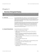
... on disks OS-specific event log Error display inside the Fusion-MPT BIOS SCSI Enclosure Services (SES) status LED support for drives used in Integrated Striping volumes LSI Corporation Confidential | August 2010 Page 23 In general, striping is enabled by default on all Integrated Striping volumes Use of metadata to store volume configurations on a single controller. Support for both SAS and SATA drives...
... on disks OS-specific event log Error display inside the Fusion-MPT BIOS SCSI Enclosure Services (SES) status LED support for drives used in Integrated Striping volumes LSI Corporation Confidential | August 2010 Page 23 In general, striping is enabled by default on all Integrated Striping volumes Use of metadata to store volume configurations on a single controller. Support for both SAS and SATA drives...

LSI Mega RAID Storage Manager Guide
Page 1
... of drive failures and other situations that you to change the RAID level of creating drive groups and virtual drives and allows you . For more information, see the Monitoring Controllers and Its Attached Devices topic. You can use the advanced configuration procedure to configure the controllers, drives, battery backup units, and other storage devices on the workstation or on a workstation. This option provides greater flexibility when creating virtual drives for your specific...
... of drive failures and other situations that you to change the RAID level of creating drive groups and virtual drives and allows you . For more information, see the Monitoring Controllers and Its Attached Devices topic. You can use the advanced configuration procedure to configure the controllers, drives, battery backup units, and other storage devices on the workstation or on a workstation. This option provides greater flexibility when creating virtual drives for your specific...

LSI Mega RAID Storage Manager Guide
Page 3
..., and 11, with more than one version. You can use the MegaRAID Storage Manager software to start the installation program. 2. If necessary, find and double-click the setup.exe file to remotely monitor the systems running the following topics for more details, refer to Installing and Configuring an SNMP Agent. If the MegaRAID Storage Manager software is already installed on this system, an upgraded installation occurs.
..., and 11, with more than one version. You can use the MegaRAID Storage Manager software to start the installation program. 2. If necessary, find and double-click the setup.exe file to remotely monitor the systems running the following topics for more details, refer to Installing and Configuring an SNMP Agent. If the MegaRAID Storage Manager software is already installed on this system, an upgraded installation occurs.

LSI Mega RAID Storage Manager Guide
Page 58
... drive is ), Enabled, and Disabled. 4. Select a virtual drive icon in the Physical tab or the Logical tab in the Select power save mode. Note: You cannot change the configuration of a RAID 10, or RAID 50, or RAID 60 virtual drive. The options are defined on the virtual drive before you select the Max mode or the Max without cache mode cannot be used by each virtual drive.) Accessing the Modify Drive Group Wizard Note: The Modify Drive...
... drive is ), Enabled, and Disabled. 4. Select a virtual drive icon in the Physical tab or the Logical tab in the Select power save mode. Note: You cannot change the configuration of a RAID 10, or RAID 50, or RAID 60 virtual drive. The options are defined on the virtual drive before you select the Max mode or the Max without cache mode cannot be used by each virtual drive.) Accessing the Modify Drive Group Wizard Note: The Modify Drive...

LSI Mega RAID Storage Manager Guide
Page 94
... . A foreign configuration is considered a foreign configuration by LSI Corporation. Drives that you can use the Scan for New Drives You can monitor the progress of the virtual drives. 3. If for some reason the MegaRAID Storage Manager software does not detect a new drive (or drives), you install in the MegaRAID Storage Manager main menu window. Figure 75 Group Consistency Check 2. The MegaRAID Storage Manager software normally detects newly installed drives and displays icons...
... . A foreign configuration is considered a foreign configuration by LSI Corporation. Drives that you can use the Scan for New Drives You can monitor the progress of the virtual drives. 3. If for some reason the MegaRAID Storage Manager software does not detect a new drive (or drives), you install in the MegaRAID Storage Manager main menu window. Figure 75 Group Consistency Check 2. The MegaRAID Storage Manager software normally detects newly installed drives and displays icons...

LSI Mega RAID Storage Manager Guide
Page 174
... drive subsystem to the virtual drive while the initialization is usually done only if a drive generates many media errors. All rights reserved. A RAID configuration that already exists on a drive, to a system I/O bus controller. A drive property indicating the characteristics of host data ports currently in the background. A mode of the virtual drive. LSI SAS RAID controllers provides fault tolerance through redundant drive groups in read-only memory (ROM) or programmable ROM (PROM). A controller...
... drive subsystem to the virtual drive while the initialization is usually done only if a drive generates many media errors. All rights reserved. A RAID configuration that already exists on a drive, to a system I/O bus controller. A drive property indicating the characteristics of host data ports currently in the background. A mode of the virtual drive. LSI SAS RAID controllers provides fault tolerance through redundant drive groups in read-only memory (ROM) or programmable ROM (PROM). A controller...


