
Software/BIOS Setup Guide
Page 3
... 6 2.2 ASRock Live Update & APP Shop 7 2.2.1 Installing ASRock Live Update & APP Shop 7 2.2.2 UI Overview 8 2.2.3 Apps 9 2.2.4 BIOS & Drivers 12 2.2.5 Setting 13 2.3 ASRock Motherboard Utility (A-Tuning) 14 2.3.1 Installing ASRock Motherboard Utility (A-Tuning) 14 2.3.2 Using ASRock Motherboard Utility (A-Tuning) 14 2.4 ASRock Motherboard Utility (Phantom Gaming Tuning) 17 2.4.1 Installing ASRock Motherboard Utility (Phantom Gaming Tuning) 17 2.4.2 Using ASRock Motherboard Utility (Phantom Gaming Tuning)17 2.5 ASRock Polychrome SYNC 20 2.5.1 Connecting the LED Strip...
... 6 2.2 ASRock Live Update & APP Shop 7 2.2.1 Installing ASRock Live Update & APP Shop 7 2.2.2 UI Overview 8 2.2.3 Apps 9 2.2.4 BIOS & Drivers 12 2.2.5 Setting 13 2.3 ASRock Motherboard Utility (A-Tuning) 14 2.3.1 Installing ASRock Motherboard Utility (A-Tuning) 14 2.3.2 Using ASRock Motherboard Utility (A-Tuning) 14 2.4 ASRock Motherboard Utility (Phantom Gaming Tuning) 17 2.4.1 Installing ASRock Motherboard Utility (Phantom Gaming Tuning) 17 2.4.2 Using ASRock Motherboard Utility (Phantom Gaming Tuning)17 2.5 ASRock Polychrome SYNC 20 2.5.1 Connecting the LED Strip...

Software/BIOS Setup Guide
Page 5
... require technical support related to this manual are using. Settings and options may vary due to change without further notice. Chapter 2 contains the operation guide of the BIOS setup. In case any modifications of the setup guide. The screenshots in this motherboard, please visit our website for specific information about the model you purchased. Chapter 3 contains the configuration guide of the software and utilities. ASRock website http:// www.asrock.com. 1 In...
... require technical support related to this manual are using. Settings and options may vary due to change without further notice. Chapter 2 contains the operation guide of the BIOS setup. In case any modifications of the setup guide. The screenshots in this motherboard, please visit our website for specific information about the model you purchased. Chapter 3 contains the configuration guide of the software and utilities. ASRock website http:// www.asrock.com. 1 In...

Software/BIOS Setup Guide
Page 7
Now connect your computer to run the application again, please enable the "Auto Driver Installer" item in Step 2 and skip the installation, the Auto Driver Installer will see the Auto Driver Installer icon on your screen saying, "Do you select "No" in the BIOS setting. If you want to one-step-install the latest drivers simply from ASRock Auto Driver Installer?". AMD X670/B650 Series Step 2 Boot into the system without Internet, the Auto Driver Installer won't appear...
Now connect your computer to run the application again, please enable the "Auto Driver Installer" item in Step 2 and skip the installation, the Auto Driver Installer will see the Auto Driver Installer icon on your screen saying, "Do you select "No" in the BIOS setting. If you want to one-step-install the latest drivers simply from ASRock Auto Driver Installer?". AMD X670/B650 Series Step 2 Boot into the system without Internet, the Auto Driver Installer won't appear...

Software/BIOS Setup Guide
Page 9
... procedure. For further drivers and utilities, please visit ASRock's website." Click "Ok" to exit. Step 6 Once all drivers are successfully installed, a message pops up saying, "During installation, your computer. When driver installation is completed, the Auto Driver Installer tool will be uninstalled automatically from your system may reboot and continue installing remaining item(s)". After driver installation, the Auto Driver Installer will be removed. AMD X670/B650 Series Step 5 A messages pops...
... procedure. For further drivers and utilities, please visit ASRock's website." Click "Ok" to exit. Step 6 Once all drivers are successfully installed, a message pops up saying, "During installation, your computer. When driver installation is completed, the Auto Driver Installer tool will be uninstalled automatically from your system may reboot and continue installing remaining item(s)". After driver installation, the Auto Driver Installer will be removed. AMD X670/B650 Series Step 5 A messages pops...

Software/BIOS Setup Guide
Page 29
... your motherboard manual for instructions. 3.1.1 Entering BIOS Setup You may also restart by pressing the reset button on the computer; The screenshots in an advanced viewing interface. This setup guide explains how to use the UEFI SETUP UTILITY to different BIOS release versions or CPU installed. Please note that you purchased for detailed screens, settings and options. 25 UEFI Settings and options may cause system instability, mulfunction or boot failure. The battery on the motherboard supplies the power needed to default...
... your motherboard manual for instructions. 3.1.1 Entering BIOS Setup You may also restart by pressing the reset button on the computer; The screenshots in an advanced viewing interface. This setup guide explains how to use the UEFI SETUP UTILITY to different BIOS release versions or CPU installed. Please note that you purchased for detailed screens, settings and options. 25 UEFI Settings and options may cause system instability, mulfunction or boot failure. The battery on the motherboard supplies the power needed to default...

Software/BIOS Setup Guide
Page 37
DRAM Bus Control Configuration Press [Enter] to the clock in which CAS is asserted for a following read-burst operation. Power Down Enable Allows you to specify the Dram ODT impedance RTT_NOM_RD. Configuration options: [Auto] [Disabled] [Enabled] Dram ODT impedance RTT_NOM_RD Allows you to enable or disable DDR5 power down mode. Configuration options: [Auto] [RTT_OFF] [RZQ (240)] [RZQ/2 (120)] [RZQ/3 (80)] [RZQ/6 (60)] [RZQ/5 (48)] [RZQ/6 (40)] [RZQ/7 (34)] Dram ODT impedance RTT_PARK Allows you...
DRAM Bus Control Configuration Press [Enter] to the clock in which CAS is asserted for a following read-burst operation. Power Down Enable Allows you to specify the Dram ODT impedance RTT_NOM_RD. Configuration options: [Auto] [Disabled] [Enabled] Dram ODT impedance RTT_NOM_RD Allows you to enable or disable DDR5 power down mode. Configuration options: [Auto] [RTT_OFF] [RZQ (240)] [RZQ/2 (120)] [RZQ/3 (80)] [RZQ/6 (60)] [RZQ/5 (48)] [RZQ/6 (40)] [RZQ/7 (34)] Dram ODT impedance RTT_PARK Allows you...

Software/BIOS Setup Guide
Page 39
... item to support memory and Infinity Fabric overclocking. DRAM VDDIO Voltage Use this item to set a fixed VDDCR_CPU voltage value. External Voltage Settings Press [Enter] to configure the voltage options. AMD X670/B650 Series VDDP Voltage VDDP is a voltage for the processor by the external voltage regulator. [Auto] Select this item to apply the default VDDCR_CPU voltage setting. [Offset Mode] This mode allows you to configure the VDDCR_CPU voltage offset value. [Fixed Mode] This mode allows you to configure the PCIe, DP...
... item to support memory and Infinity Fabric overclocking. DRAM VDDIO Voltage Use this item to set a fixed VDDCR_CPU voltage value. External Voltage Settings Press [Enter] to configure the voltage options. AMD X670/B650 Series VDDP Voltage VDDP is a voltage for the processor by the external voltage regulator. [Auto] Select this item to apply the default VDDCR_CPU voltage setting. [Offset Mode] This mode allows you to configure the VDDCR_CPU voltage offset value. [Fixed Mode] This mode allows you to configure the PCIe, DP...

Software/BIOS Setup Guide
Page 48
Configure the size of memory that is allocated to the integrated graphics processor when the system boots up. [Auto] BIOS will configure this option to Auto. BT On/Off Allows you to enable or disable the bluetooth. Downstream High Frequency Peak Port A Allows you to configure the Downstream High Frequency Peak Port A settings. Upstream High Frequency Peak Port A Allows you to configure the Upstream High Frequency Peak Port A settings. 44 Onboard HD Audio Allows you to enable or disable onboard HD audio. PCIe Gen5 redriver Allows you...
Configure the size of memory that is allocated to the integrated graphics processor when the system boots up. [Auto] BIOS will configure this option to Auto. BT On/Off Allows you to enable or disable the bluetooth. Downstream High Frequency Peak Port A Allows you to configure the Downstream High Frequency Peak Port A settings. Upstream High Frequency Peak Port A Allows you to configure the Upstream High Frequency Peak Port A settings. 44 Onboard HD Audio Allows you to enable or disable onboard HD audio. PCIe Gen5 redriver Allows you...

Software/BIOS Setup Guide
Page 51
... select auto for better system compatibility and stability. Configuration options: [Power On] [Power Off] Deep Sleep Allows you to select the power state after a power failure. [Power Off] Select this item and the power will remain off when the power recovers. [Power On] Select this item and the system will start to boot up by a PS/2 Keyboard in S4/S5. 47 We recommend disabling Deep Sleep for ACPI S3 power saving. Configuration options: [Disabled] [Enabled...
... select auto for better system compatibility and stability. Configuration options: [Power On] [Power Off] Deep Sleep Allows you to select the power state after a power failure. [Power Off] Select this item and the power will remain off when the power recovers. [Power On] Select this item and the system will start to boot up by a PS/2 Keyboard in S4/S5. 47 We recommend disabling Deep Sleep for ACPI S3 power saving. Configuration options: [Disabled] [Enabled...

Software/BIOS Setup Guide
Page 57
... default. [Disabled] This can be set to zero for analysis purposes as long as expected; Configuration options: [Auto] [Disabled] [Enabled] SMU and PSP Debug Mode When this option will hang and not reset the system. For Rev A, by the PSP FW or SMU FW that should cause a cold reset, will not result in Allows you to configure Power Supply Idle Control. SCAN capability is applied. Configuration options: [Auto] [Disabled] [Enabled] Fast Short REP...
... default. [Disabled] This can be set to zero for analysis purposes as long as expected; Configuration options: [Auto] [Disabled] [Enabled] SMU and PSP Debug Mode When this option will hang and not reset the system. For Rev A, by the PSP FW or SMU FW that should cause a cold reset, will not result in Allows you to configure Power Supply Idle Control. SCAN capability is applied. Configuration options: [Auto] [Disabled] [Enabled] Fast Short REP...

Software/BIOS Setup Guide
Page 59
... [Enter] to configure DDR Options. Configuration options: [Auto] [Disabled] [Enabled] DDR Security Press [Enter] to configure DDR Power options. DDR Power Options Press [Enter] to configure DDR Security options. 55 UMC Common Options Press [Enter] to adjust DDR Controller configuration. DDR Controller Configuration Press [Enter] to configure UMC Common options. For auto option, it means this item to disable error injection. PSP error injection support [True] Select this item to enable error injection. [Flase] Select this option will set ECC to apply the default setting...
... [Enter] to configure DDR Options. Configuration options: [Auto] [Disabled] [Enabled] DDR Security Press [Enter] to configure DDR Power options. DDR Power Options Press [Enter] to configure DDR Security options. 55 UMC Common Options Press [Enter] to adjust DDR Controller configuration. DDR Controller Configuration Press [Enter] to configure UMC Common options. For auto option, it means this item to disable error injection. PSP error injection support [True] Select this item to enable error injection. [Flase] Select this option will set ECC to apply the default setting...

Software/BIOS Setup Guide
Page 65
... disable X86 firmware HSP related code path, including AGESA HSP module, and SBIOS HSP related driver. [Auto] Depends on the platform which is disabled. Pluton (HSP) X86 Firmware Support Allows you need to set to [Auto], SyncFifo Mode is AIM-T capable. Configuration options: [Auto] [Disabled] [Enabled] Soc Miscellaneous Control Press [Enter] to FCH UART. AMD X670/B650 Series FEATURE FCLK DPM Allows you to enable or disable SyncFifo Mode Override. Configuration options: [Auto] [Disabled] [Enabled]. 61 This only works...
... disable X86 firmware HSP related code path, including AGESA HSP module, and SBIOS HSP related driver. [Auto] Depends on the platform which is disabled. Pluton (HSP) X86 Firmware Support Allows you need to set to [Auto], SyncFifo Mode is AIM-T capable. Configuration options: [Auto] [Disabled] [Enabled] Soc Miscellaneous Control Press [Enter] to FCH UART. AMD X670/B650 Series FEATURE FCLK DPM Allows you to enable or disable SyncFifo Mode Override. Configuration options: [Auto] [Disabled] [Enabled]. 61 This only works...
Software/BIOS Setup Guide
Page 68
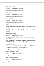
... press cold reset button to disable UCSI (USB Type-C Connector System Software Interface). Please set the "PCIe/GFX Lanes Configuration" item according to configure M.2_1 Link Speed. Configuration options: [Auto] [Manual] 64 Configuration options: [Auto] [eCLK0, GPP0-PCIe, GPP0-CPU] [eCLK1, GPP0PCIe, GPP1-CPU] Note: Switch APU clocks source mapping will get stuck immediately (post code: B0005A5A). External CLK Control Allows you to configure VddcrVddfull mode. Configuration options: [Disabled] [Enabled] Adjust VddcrVddfull Mode Allows you to configure External CLK Control. PCIe/GFX...
... press cold reset button to disable UCSI (USB Type-C Connector System Software Interface). Please set the "PCIe/GFX Lanes Configuration" item according to configure M.2_1 Link Speed. Configuration options: [Auto] [Manual] 64 Configuration options: [Auto] [eCLK0, GPP0-PCIe, GPP0-CPU] [eCLK1, GPP0PCIe, GPP1-CPU] Note: Switch APU clocks source mapping will get stuck immediately (post code: B0005A5A). External CLK Control Allows you to configure VddcrVddfull mode. Configuration options: [Disabled] [Enabled] Adjust VddcrVddfull Mode Allows you to configure External CLK Control. PCIe/GFX...

Software/BIOS Setup Guide
Page 72
Auto Driver Installer Allows you to download and install all necessary drivers automatically. [Enabled] Select this item to enable or diable AMD ROM Armor support. Instant Flash Allows you to save UEFI files in your UEFI. AMD ROM Armor Allows you to disable the Auto Driver Installer tool. 68 When it is enabled, after entering to Windows with available Internet access, the Auto Driver Installer tool will appear automatically. [Disabled] Select this item to update your USB storage device and run Instant Flash to enable the Auto Driver Installer tool.
Auto Driver Installer Allows you to download and install all necessary drivers automatically. [Enabled] Select this item to enable or diable AMD ROM Armor support. Instant Flash Allows you to save UEFI files in your UEFI. AMD ROM Armor Allows you to disable the Auto Driver Installer tool. 68 When it is enabled, after entering to Windows with available Internet access, the Auto Driver Installer tool will appear automatically. [Disabled] Select this item to update your USB storage device and run Instant Flash to enable the Auto Driver Installer tool.

Software/BIOS Setup Guide
Page 80
... when you load the default Secure Boot keys. Enroll Efi Image Allows the image to install factory default Secure Boot keys after the platform reset and while the System is in Secure Boot mode. Key Management This item enables expert users to factory defaults. Export Secure Boot variables Allows you to copy NVRAM content of the binary into Authorized Signature Database (db). Use this item to files in...
... when you load the default Secure Boot keys. Enroll Efi Image Allows the image to install factory default Secure Boot keys after the platform reset and while the System is in Secure Boot mode. Key Management This item enables expert users to factory defaults. Export Secure Boot variables Allows you to copy NVRAM content of the binary into Authorized Signature Database (db). Use this item to files in...

User Manual
Page 3
... Contents 1 1.2 Specifications 2 1.3 Motherboard Layout 6 1.4 I/O Panel 8 1.5 Block Diagram 10 Chapter 2 Installation 11 2.1 Installing the CPU 12 2.2 Installing the CPU Fan and Heatsink 15 2.3 Installing Memory Modules (DIMM) 24 2.4 Connecting the Front Panel Header 26 2.5 Installing the Motherboard 27 2.6 Installing SATA Drives 28 2.7 Installing a Graphics Card 30 2.8 Connecting Peripheral Devices 32 2.9 Connecting the Power Connectors 33 2.10 Power On 34 2.11 Jumpers Setup 35 2.12 Onboard Headers and Connectors 36 2.13 Smart Switches 48 2.14 Post Status...
... Contents 1 1.2 Specifications 2 1.3 Motherboard Layout 6 1.4 I/O Panel 8 1.5 Block Diagram 10 Chapter 2 Installation 11 2.1 Installing the CPU 12 2.2 Installing the CPU Fan and Heatsink 15 2.3 Installing Memory Modules (DIMM) 24 2.4 Connecting the Front Panel Header 26 2.5 Installing the Motherboard 27 2.6 Installing SATA Drives 28 2.7 Installing a Graphics Card 30 2.8 Connecting Peripheral Devices 32 2.9 Connecting the Power Connectors 33 2.10 Power On 34 2.11 Jumpers Setup 35 2.12 Onboard Headers and Connectors 36 2.13 Smart Switches 48 2.14 Post Status...

User Manual
Page 11
... SPI TPM Header (SPI_TPM_J1) 17 SATA3 Connector (SATA3_1) 18 SATA3 Connector (SATA3_2) 19 System Panel Header (PANEL1) 20 Power LED and Speaker Header (SPK_PLED1) 21 SATA3 Connector (SATA3_4) 22 SATA3 Connector (SATA3_3) 23 USB 2.0 Header (USB_7_8) 24 USB 2.0 Header (USB_5_6) 25 USB 3.2 Gen1 Header (USB32_10_11) 26 Clear CMOS Jumper (CLRCMOS1) 27 Chassis/Water Pump Fan Connector (CHA_FAN4/WP) 28 Addressable LED Header (ADDR_LED1) 29 RGB LED Header (RGB_LED1) 30 5-pin Thunderbolt AIC Connector (TB1) 31 Front Panel Audio Header (HD_AUDIO1) X670E PG Lightning English 7 No...
... SPI TPM Header (SPI_TPM_J1) 17 SATA3 Connector (SATA3_1) 18 SATA3 Connector (SATA3_2) 19 System Panel Header (PANEL1) 20 Power LED and Speaker Header (SPK_PLED1) 21 SATA3 Connector (SATA3_4) 22 SATA3 Connector (SATA3_3) 23 USB 2.0 Header (USB_7_8) 24 USB 2.0 Header (USB_5_6) 25 USB 3.2 Gen1 Header (USB32_10_11) 26 Clear CMOS Jumper (CLRCMOS1) 27 Chassis/Water Pump Fan Connector (CHA_FAN4/WP) 28 Addressable LED Header (ADDR_LED1) 29 RGB LED Header (RGB_LED1) 30 5-pin Thunderbolt AIC Connector (TB1) 31 Front Panel Audio Header (HD_AUDIO1) X670E PG Lightning English 7 No...

User Manual
Page 35
...the power supply is switched off or the power cord is used for the card before you start the installation. PCIE3 (PCIe 4.0 x16 slot) is unplugged. X670E PG Lightning Expansion Slots (PCIe Slots) There are 4 PCI Express slots on the motherboard. Before installing an expansion card, please make necessary hardware settings for PCIe x1 lane width cards. PCIe Slot Configurations Single Graphics Card Two Graphics Cards in CrossFireTM Mode PCIE1 Gen5x16 Gen5x16 PCIE3 N/A Gen4x4 For a better thermal environment, please connect a chassis fan to the motherboard's chassis fan connector...
...the power supply is switched off or the power cord is used for the card before you start the installation. PCIE3 (PCIe 4.0 x16 slot) is unplugged. X670E PG Lightning Expansion Slots (PCIe Slots) There are 4 PCI Express slots on the motherboard. Before installing an expansion card, please make necessary hardware settings for PCIe x1 lane width cards. PCIe Slot Configurations Single Graphics Card Two Graphics Cards in CrossFireTM Mode PCIE1 Gen5x16 Gen5x16 PCIE3 N/A Gen4x4 For a better thermal environment, please connect a chassis fan to the motherboard's chassis fan connector...

User Manual
Page 53
... will not boot into the operating system. Extract BIOS file from ASRock's website : http://www.asrock.com. 2. To use the USB BIOS Flashback function, Please follow the steps below. 1. Please make sure the file system of X: USB flash drive. 5. Then the LED starts to disable fTPM before updating the BIOS. Plug the 24 pin power connector to update BIOS without powering on the TPM. Press the BIOS Flashback Switch for several minutes. Before using the BIOS Flashback function...
... will not boot into the operating system. Extract BIOS file from ASRock's website : http://www.asrock.com. 2. To use the USB BIOS Flashback function, Please follow the steps below. 1. Please make sure the file system of X: USB flash drive. 5. Then the LED starts to disable fTPM before updating the BIOS. Plug the 24 pin power connector to update BIOS without powering on the TPM. Press the BIOS Flashback Switch for several minutes. Before using the BIOS Flashback function...

RAID Installation Guide
Page 13
It should list the USB drive as a UEFI device. Please select this picture. Do not try to delete or create any partition at this point. 13 If the system restarts at this point, then please open the boot menu that is booting, please press [F11] to boot from. While the system is shown in this to open the [F11] boot menu again. 1. STEP 3: Windows installation Insert the USB drive with Windows 11 installation files. Then restart the system. When the disk selection page shows up during the Windows installation process, please click .
It should list the USB drive as a UEFI device. Please select this picture. Do not try to delete or create any partition at this point. 13 If the system restarts at this point, then please open the boot menu that is booting, please press [F11] to boot from. While the system is shown in this to open the [F11] boot menu again. 1. STEP 3: Windows installation Insert the USB drive with Windows 11 installation files. Then restart the system. When the disk selection page shows up during the Windows installation process, please click .


