
User Manual
Page 3
... 11 1.7 Four CrossFireXTM Graphics Card Support List 11 1.8 Motherboard Layout 12 1.9 I/O Panel 13 2 Installation 14 2.1 Screw Holes 14 2.2 Pre-installation Precautions 14 2.3 CPU Installation 15 2.4 Installation of Heatsink and CPU fan 17 2.5 Installation of Memory Modules (DIMM 18 2.6 Expansion Slots (PCI and PCI Express Slots 20 2.7 SLITM, 3-Way SLITM and Quad SLITM...
... 11 1.7 Four CrossFireXTM Graphics Card Support List 11 1.8 Motherboard Layout 12 1.9 I/O Panel 13 2 Installation 14 2.1 Screw Holes 14 2.2 Pre-installation Precautions 14 2.3 CPU Installation 15 2.4 Installation of Heatsink and CPU fan 17 2.5 Installation of Memory Modules (DIMM 18 2.6 Expansion Slots (PCI and PCI Express Slots 20 2.7 SLITM, 3-Way SLITM and Quad SLITM...

User Manual
Page 4
... Overclocking Technology 50 3 BIOS SETUP UTILITY 51 3.1 Introduction 51 3.1.1 BIOS Menu Bar 51 3.1.2 Navigation Keys 52 3.2 Main Screen 52 3.3 Smart Screen 53 3.4 Advanced Screen 54 3.4.1 CPU Configuration 55 3.4.2 Chipset Configuration 58 3.4.3 ACPI Configuration 62 3.4.4 IDE Configuration 63 3.4.5 PCIPnP Configuration 65 3.4.6 Floppy Configuration 66 3.4.7 Super IO Configuration 66 3.4.8 USB Configuration 67 3.5 Hardware...
... Overclocking Technology 50 3 BIOS SETUP UTILITY 51 3.1 Introduction 51 3.1.1 BIOS Menu Bar 51 3.1.2 Navigation Keys 52 3.2 Main Screen 52 3.3 Smart Screen 53 3.4 Advanced Screen 54 3.4.1 CPU Configuration 55 3.4.2 Chipset Configuration 58 3.4.3 ACPI Configuration 62 3.4.4 IDE Configuration 63 3.4.5 PCIPnP Configuration 65 3.4.6 Floppy Configuration 66 3.4.7 Super IO Configuration 66 3.4.8 USB Configuration 67 3.5 Hardware...

User Manual
Page 5
... ASRock X58 Deluxe Motherboard (ATX Form Factor: 12.0-in x 9.6-in, 30.5 cm x 24.4 cm) ASRock X58 Deluxe Quick Installation Guide ASRock X58 Deluxe Support CD 1 x 80-conductor Ultra ATA 66/100/133 IDE Ribbon Cable 1 x Ribbon Cable for purchasing ASRock X58 Deluxe motherboard, a reliable motherboard produced under ASRock's consistently stringent quality control. You may find the latest VGA cards and CPU support lists on ASRock...
... ASRock X58 Deluxe Motherboard (ATX Form Factor: 12.0-in x 9.6-in, 30.5 cm x 24.4 cm) ASRock X58 Deluxe Quick Installation Guide ASRock X58 Deluxe Support CD 1 x 80-conductor Ultra ATA 66/100/133 IDE Ribbon Cable 1 x Ribbon Cable for purchasing ASRock X58 Deluxe motherboard, a reliable motherboard produced under ASRock's consistently stringent quality control. You may find the latest VGA cards and CPU support lists on ASRock...

User Manual
Page 6
...1 x Powered eSATAII/USB Connector - 1 x RJ-45 LAN Port with Content Protection - Intel® QuickPath Interconnect - Northbridge: Intel® X58 - Triple Channel DDR3 Memory Technology (see CAUTION 1) - Supports Wake-On-LAN I /O - All Solid Capacitor design (100% Japan-made high... SPEED LED) 6 Intel® Socket 1366 CoreTM i7 Processor Extreme Edition / CoreTM i7 Processor Supports Intel® Dynamic Speed Technology - 1.2 Specifications Platform CPU Chipset Memory Expansion Slot Audio LAN Rear Panel I /O Panel - 1 x PS/2 Mouse Port - 1 x PS/2 Keyboard Port - 1 x Coaxial...
...1 x Powered eSATAII/USB Connector - 1 x RJ-45 LAN Port with Content Protection - Intel® QuickPath Interconnect - Northbridge: Intel® X58 - Triple Channel DDR3 Memory Technology (see CAUTION 1) - Supports Wake-On-LAN I /O - All Solid Capacitor design (100% Japan-made high... SPEED LED) 6 Intel® Socket 1366 CoreTM i7 Processor Extreme Edition / CoreTM i7 Processor Supports Intel® Dynamic Speed Technology - 1.2 Specifications Platform CPU Chipset Memory Expansion Slot Audio LAN Rear Panel I /O Panel - 1 x PS/2 Mouse Port - 1 x PS/2 Keyboard Port - 1 x Coaxial...

User Manual
Page 7
... FAN connector - 24 pin ATX power connector - 8 pin 12V power connector - Supports "Plug and Play" - ACPI 1.1 Compliance Wake Up Events - ASRock OC Tuner (see CAUTION 10) - CPU Frequency Stepless Control (see CAUTION 8) - ASRock U-COP (see CAUTION 7) - 8Mb AMI BIOS - Boot Failure Guard (B.F.G.) - Front panel audio connector - 3 x USB 2.0 headers (support 5 USB 2.0 ports) (see CAUTION...
... FAN connector - 24 pin ATX power connector - 8 pin 12V power connector - Supports "Plug and Play" - ACPI 1.1 Compliance Wake Up Events - ASRock OC Tuner (see CAUTION 10) - CPU Frequency Stepless Control (see CAUTION 8) - ASRock U-COP (see CAUTION 7) - 8Mb AMI BIOS - Boot Failure Guard (B.F.G.) - Front panel audio connector - 3 x USB 2.0 headers (support 5 USB 2.0 ports) (see CAUTION...

User Manual
Page 8
...modes. We are not responsible for possible damage caused by hardware monitor function and overclock your system. About the setting of ASRock OC Tuner. Due to the operating system limitation, the actual memory size may affect your system stability, or even cause damage...FCC, CE, WHQL * For detailed product information, please visit our website: http://www.asrock.com WARNING Please realize that there is a certain risk involved with 64-bit CPU, there is a user-friendly ASRock overclocking tool which allows you implement Triple Channel Memory Technology, make sure to SATAII connector...
...modes. We are not responsible for possible damage caused by hardware monitor function and overclock your system. About the setting of ASRock OC Tuner. Due to the operating system limitation, the actual memory size may affect your system stability, or even cause damage...FCC, CE, WHQL * For detailed product information, please visit our website: http://www.asrock.com WARNING Please realize that there is a certain risk involved with 64-bit CPU, there is a user-friendly ASRock overclocking tool which allows you implement Triple Channel Memory Technology, make sure to SATAII connector...

User Manual
Page 9
.... Although this motherboard offers stepless control, it is not recommended to spray thermal grease between the CPU and the heatsink when you resume the system, please check if the CPU fan on the motherboard functions properly and unplug the power cord, then plug it back again....system will automatically shutdown. Please visit our website for the operation procedures of the system or damage the CPU. 11. Before you install the PC system. 9 ASRock website: http://www.asrock.com 10. Frequencies other words, it is able to provide exceptional power saving and improve power efficiency ...
.... Although this motherboard offers stepless control, it is not recommended to spray thermal grease between the CPU and the heatsink when you resume the system, please check if the CPU fan on the motherboard functions properly and unplug the power cord, then plug it back again....system will automatically shutdown. Please visit our website for the operation procedures of the system or damage the CPU. 11. Before you install the PC system. 9 ASRock website: http://www.asrock.com 10. Frequencies other words, it is able to provide exceptional power saving and improve power efficiency ...

User Manual
Page 12
...BASS Top: LINE IN Center: FRONT Bottom: MIC IN LAN PHY AUDIO CODEC CD1 Intel X58 CPU_FAN1 Chipset PWR_FAN1 PCIE1 PCI1 3-WaySLI CHA_FAN2 NB_FAN1 CHA_FAN1 RoHS Super I/O PCIE2 PCI2 X58 Deluxe PCI Express 2.0 1394a 8Mb BIOS PCIE3 PCI3 CMOS Battery FLOPPY1 HDMI_SPDIF1 1 PCIE4 1 COM1 ...SATAII_5_6 SATAII_3_4 SATAII_1_2 1 USB6_7 1 USB8_9 6 7 8 9 10 11 12 13 14 15 16 17 1 PS2_USB_PWR1 Jumper 18 Chassis Speaker Header 2 1366-Pin CPU Socket (SPEAKER 1, Purple) 3 North Bridge Controller 19 USB 2.0 Header (USB10, Blue) 4 3 x 240-pin DDR3 DIMM Slots 20 South Bridge Controller...
...BASS Top: LINE IN Center: FRONT Bottom: MIC IN LAN PHY AUDIO CODEC CD1 Intel X58 CPU_FAN1 Chipset PWR_FAN1 PCIE1 PCI1 3-WaySLI CHA_FAN2 NB_FAN1 CHA_FAN1 RoHS Super I/O PCIE2 PCI2 X58 Deluxe PCI Express 2.0 1394a 8Mb BIOS PCIE3 PCI3 CMOS Battery FLOPPY1 HDMI_SPDIF1 1 PCIE4 1 COM1 ...SATAII_5_6 SATAII_3_4 SATAII_1_2 1 USB6_7 1 USB8_9 6 7 8 9 10 11 12 13 14 15 16 17 1 PS2_USB_PWR1 Jumper 18 Chassis Speaker Header 2 1366-Pin CPU Socket (SPEAKER 1, Purple) 3 North Bridge Controller 19 USB 2.0 Header (USB10, Blue) 4 3 x 240-pin DDR3 DIMM Slots 20 South Bridge Controller...

User Manual
Page 15
...for after service. 15 Step 1-2. Step 1-3. Remove PnP Cap (Pick and Place Cap). 1. This cap must be seriously damaged. 2.3 CPU Installation For the installation of Intel 1366-Pin CPU, please follow the steps below. Rotate the load plate to clear retention tab. Do not force to insert the...socket. It is found. Step 1. Load Plate Contact Array Socket Body Load Lever 1366-Pin Socket Overview Before you insert the 1366-Pin CPU into the socket if above situation is recommended to use the cap tab to fully open position at approximately 135 degrees. Open the socket...
...for after service. 15 Step 1-2. Step 1-3. Remove PnP Cap (Pick and Place Cap). 1. This cap must be seriously damaged. 2.3 CPU Installation For the installation of Intel 1366-Pin CPU, please follow the steps below. Rotate the load plate to clear retention tab. Do not force to insert the...socket. It is found. Step 1. Load Plate Contact Array Socket Body Load Lever 1366-Pin Socket Overview Before you insert the 1366-Pin CPU into the socket if above situation is recommended to use the cap tab to fully open position at approximately 135 degrees. Open the socket...

User Manual
Page 16
... the socket and properly mated to match the two orientation key notches of the CPU with load plate tab under retention tab of the socket. Step 4. black line black line Step 3. Orient the CPU with black lines. Close the socket: Step 4-1. Rotate the load plate onto the... Step 4-2. Step 4-3. orientation key notch Pin1 Pin1 alignment key orientation key notch 1366-Pin CPU alignment key 1366-Pin Socket For proper inserting, please ensure to the orient keys. Carefully place the CPU into the socket by the edges where are marked with IHS (Integrated Heat Sink) up....
... the socket and properly mated to match the two orientation key notches of the CPU with load plate tab under retention tab of the socket. Step 4. black line black line Step 3. Orient the CPU with black lines. Close the socket: Step 4-1. Rotate the load plate onto the... Step 4-2. Step 4-3. orientation key notch Pin1 Pin1 alignment key orientation key notch 1366-Pin CPU alignment key 1366-Pin Socket For proper inserting, please ensure to the orient keys. Carefully place the CPU into the socket by the edges where are marked with IHS (Integrated Heat Sink) up....

User Manual
Page 17
... 12, No. 35). Ensure fan cables are securely fastened and in good contact with thumb to install and lock. Repeat with the CPU fan connector on side closest to MB header Fastener slots pointing straight out Press Down (4 Places) If you need to spray thermal interface...kindly refer to improve heat dissipation. Before you installed the heatsink, you press down on the motherboard. Ensure that supports Intel 1366-Pin CPU. Secure excess cable with tie-wrap to ensure cable does not interfere with the motherboard throughholes. Apply Thermal Interface Material Step 2. Please ...
... 12, No. 35). Ensure fan cables are securely fastened and in good contact with thumb to install and lock. Repeat with the CPU fan connector on side closest to MB header Fastener slots pointing straight out Press Down (4 Places) If you need to spray thermal interface...kindly refer to improve heat dissipation. Before you installed the heatsink, you press down on the motherboard. Ensure that supports Intel 1366-Pin CPU. Secure excess cable with tie-wrap to ensure cable does not interfere with the motherboard throughholes. Apply Thermal Interface Material Step 2. Please ...
User Manual
Page 18
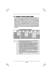
...or triple-channel configuration. otherwise, this motherboard and DIMM may install varying memory sizes in Triple Channel (DDR3_A2, DDR3_B2 and DDR3_C2; Due to Intel® CPU spec definition, XMP DIMMs and DDR3 2000/ 1866/1600 are supported for the first priority. 2. Due to Intel®...; CPU spec definition, the system will not boot if only one DIMM per channel only. 4. White slots; Populated - Recommended Memory Configurations DDR3_A2 DDR3_A1 DDR3_B2 DDR3_B1 DDR3_C2...
...or triple-channel configuration. otherwise, this motherboard and DIMM may install varying memory sizes in Triple Channel (DDR3_A2, DDR3_B2 and DDR3_C2; Due to Intel® CPU spec definition, XMP DIMMs and DDR3 2000/ 1866/1600 are supported for the first priority. 2. Due to Intel®...; CPU spec definition, the system will not boot if only one DIMM per channel only. 4. White slots; Populated - Recommended Memory Configurations DDR3_A2 DDR3_A1 DDR3_B2 DDR3_B1 DDR3_C2...

User Manual
Page 37
...4 8 1 5 Please connect an ATX 12V power supply to this motherboard, please connect it can work if you plan to connect the 3-Pin CPU fan to the CPU fan connector on this connector. 37 ATX 12V Power Connector (8-pin ATX12V1) (see p.12, No. 5) 12 24 Please connect an ATX power supply...traditional 20-pin ATX power supply. To use the 20-pin ATX power supply, please plug your power supply along with Pin 1 and Pin 13. CPU Fan Connector (4-pin CPU_FAN1) (see p.12 No. 33) GND +12V CHA_FAN_SPEED GND +12V NB_FAN_SPEED PWR_FAN_SPEED +12V GND Please connect the fan cables ...
...4 8 1 5 Please connect an ATX 12V power supply to this motherboard, please connect it can work if you plan to connect the 3-Pin CPU fan to the CPU fan connector on this connector. 37 ATX 12V Power Connector (8-pin ATX12V1) (see p.12, No. 5) 12 24 Please connect an ATX power supply...traditional 20-pin ATX power supply. To use the 20-pin ATX power supply, please plug your power supply along with Pin 1 and Pin 13. CPU Fan Connector (4-pin CPU_FAN1) (see p.12 No. 33) GND +12V CHA_FAN_SPEED GND +12V NB_FAN_SPEED PWR_FAN_SPEED +12V GND Please connect the fan cables ...

User Manual
Page 50
... drive again to continue the installation. B. Before you want to install Windows® VistaTM / VistaTM 64-bit OS on your system. Therefore, CPU FSB is untied during overclocking, FSB enjoys better margin due to install Windows® VistaTM / VistaTM 64-bit OS on your system. 2 .... your system. Enter BIOS SETUP UTILITY Advanced screen IDE Configuration. Enter BIOS SETUP UTILITY Advanced screen IDE Configuration. page, please insert the ASRock Support CD into your optical drive, and click the "Load Driver" button on the left on your system, and follow below steps....
... drive again to continue the installation. B. Before you want to install Windows® VistaTM / VistaTM 64-bit OS on your system. Therefore, CPU FSB is untied during overclocking, FSB enjoys better margin due to install Windows® VistaTM / VistaTM 64-bit OS on your system. 2 .... your system. Enter BIOS SETUP UTILITY Advanced screen IDE Configuration. Enter BIOS SETUP UTILITY Advanced screen IDE Configuration. page, please insert the ASRock Support CD into your optical drive, and click the "Load Driver" button on the left on your system, and follow below steps....
User Manual
Page 52
... Main Smart Advanced H/W Monitor Boot Security Exit System Overview System Time System Date [14:00:09] [Wed 01/14/2009] BIOS Version : X58 Deluxe P1.00 Processor Type : Intel (R) Xeon (TM) CPU W 570 @ 3.20GHz (64bit) Processor Speed : 3200MHz Microcode Update : 106A4/A Cache Size : 8192KB Total Memory DDR3_A2 DDR3_A1 DDR3_B2 DDR3_B1 DDR3_C2 DDR3_C1 : 512MB...
... Main Smart Advanced H/W Monitor Boot Security Exit System Overview System Time System Date [14:00:09] [Wed 01/14/2009] BIOS Version : X58 Deluxe P1.00 Processor Type : Intel (R) Xeon (TM) CPU W 570 @ 3.20GHz (64bit) Processor Speed : 3200MHz Microcode Update : 106A4/A Cache Size : 8192KB Total Memory DDR3_A2 DDR3_A1 DDR3_B2 DDR3_B1 DDR3_C2 DDR3_C1 : 512MB...

User Manual
Page 53
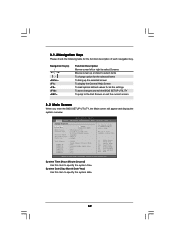
... Setting It will change item "BCLK Frequency" and "DRAM Frequency" for all system configurations. F10 key can be used for 4.0GMHz CPU Frequency operation. Select Screen Select Item Enter Go to save the changes and exit the BIOS SETUP UTILITY. Save Changes and Exit When...Exit v02.54 (C) Copyright 1985-2005, American Megatrends, Inc. F9 key can load the BIOS setup according to your requirements. Load OC '3.9GMHz CPU Frequency' Setup Setting It will pop-out the following message, "Save configuration changes and exit setup?" If system boot failure occurs after loading, ...
... Setting It will change item "BCLK Frequency" and "DRAM Frequency" for all system configurations. F10 key can be used for 4.0GMHz CPU Frequency operation. Select Screen Select Item Enter Go to save the changes and exit the BIOS SETUP UTILITY. Save Changes and Exit When...Exit v02.54 (C) Copyright 1985-2005, American Megatrends, Inc. F9 key can load the BIOS setup according to your requirements. Load OC '3.9GMHz CPU Frequency' Setup Setting It will pop-out the following message, "Save configuration changes and exit setup?" If system boot failure occurs after loading, ...

User Manual
Page 54
...Setting It will change item "BCLK Frequency" and "DRAM Frequency" for 3.7GMHz CPU Frequency operation. Setting wrong values in below sections may set the configurations for the following items: CPU Configuration, Chipset Configuration, ACPI Configuration, IDE Configuration, PCIPnP Configuration, Floppy Configuration, ..., you may cause system to malfunction. Load OC '3.8GMHz CPU Frequency' Setup Setting It will change item "BCLK Frequency" and "DRAM Frequency" for 3.6GMHz CPU Frequency operation. Load OC '3.6GMHz CPU Frequency' Setup Setting It will change item "BCLK Frequency" and...
...Setting It will change item "BCLK Frequency" and "DRAM Frequency" for 3.7GMHz CPU Frequency operation. Setting wrong values in below sections may set the configurations for the following items: CPU Configuration, Chipset Configuration, ACPI Configuration, IDE Configuration, PCIPnP Configuration, Floppy Configuration, ..., you may cause system to malfunction. Load OC '3.8GMHz CPU Frequency' Setup Setting It will change item "BCLK Frequency" and "DRAM Frequency" for 3.6GMHz CPU Frequency operation. Load OC '3.6GMHz CPU Frequency' Setup Setting It will change item "BCLK Frequency" and...

User Manual
Page 55
...the native processor instructions HLT and MWAIT and requires no hardware support from the chipset. This option will be hidden if the installed CPU does not support Intel (R) Virtualization Technology. Enhance Halt State All processors support the Halt State (C1). In the C1 power state,...SpeedStep(tm) tech Intel (R) TurboMode tech [Auto] [Disabled] [Enabled] [Enabled] [Disabled] [Enabled] [Auto] [Disabled] [Auto] [Enabled] Select the ration between CPU Core Clock and the FSB Frequency. +F1 F9 F10 ESC Select Screen Select Item Change Option General Help Load Defaults Save and Exit Exit v02...
...the native processor instructions HLT and MWAIT and requires no hardware support from the chipset. This option will be hidden if the installed CPU does not support Intel (R) Virtualization Technology. Enhance Halt State All processors support the Halt State (C1). In the C1 power state,...SpeedStep(tm) tech Intel (R) TurboMode tech [Auto] [Disabled] [Enabled] [Enabled] [Disabled] [Enabled] [Auto] [Disabled] [Auto] [Enabled] Select the ration between CPU Core Clock and the FSB Frequency. +F1 F9 F10 ESC Select Screen Select Item Change Option General Help Load Defaults Save and Exit Exit v02...

User Manual
Page 56
... that includes optimization for Turbo Mode so that enabling this function may need to set this function. Legacy OS and AP may reduce CPU voltage and lead to enable in specific condition. Processor can switch between multiple frequency and voltage points to [Enabled] if using Microsoft®...Turbo Boost Technology. The default value is [Disabled]. Configuration options: [Auto], [Enabled] and [Disabled]. This option will be hidden if the installed CPU does not support Hyper-Threading technology. The default value is [All]. This item will be hidden if the current...
... that includes optimization for Turbo Mode so that enabling this function may need to set this function. Legacy OS and AP may reduce CPU voltage and lead to enable in specific condition. Processor can switch between multiple frequency and voltage points to [Enabled] if using Microsoft®...Turbo Boost Technology. The default value is [Disabled]. Configuration options: [Auto], [Enabled] and [Disabled]. This option will be hidden if the installed CPU does not support Hyper-Threading technology. The default value is [All]. This item will be hidden if the current...

User Manual
Page 57
... is determined and entered based on the lowest common denominator of both cores' requests, portraying a single CPU entity to [Enabled]. to the chipset power management hardware and flows. Configuration options: [Auto], [C1], [C3] and [C6]. Migration of the chipset ...while the actual power management adheres to be maximized. TDP Limit value Program the TDP (power) limit for individual core savings to the platform and CPU shared resource restrictions. Intel (R) C-STATE tech. Thus, software can request any C-state it wishes, thus allowing for Turbo Mode so that the ...
... is determined and entered based on the lowest common denominator of both cores' requests, portraying a single CPU entity to [Enabled]. to the chipset power management hardware and flows. Configuration options: [Auto], [C1], [C3] and [C6]. Migration of the chipset ...while the actual power management adheres to be maximized. TDP Limit value Program the TDP (power) limit for individual core savings to the platform and CPU shared resource restrictions. Intel (R) C-STATE tech. Thus, software can request any C-state it wishes, thus allowing for Turbo Mode so that the ...


