
User Manual
Page 3
... 10 1.4 ASRock 6CH I/O PlusTM 11 2 Installation 12 2.1 Screw Holes 12 2.2 Pre-installation Precautions 12 2.3 CPU Installation 13 2.4 Installation of Heatsink and CPU fan 15 2.5 Installation of Memory Modules (DIMM 16 2.6 Expansion Slots (PCI and PCI Express Slots 17 2.7 DVI Graphics-SI Card Installation Guide 18 2.8 Jumpers Setup 20 2.9 Onboard Headers and Connectors 21...
... 10 1.4 ASRock 6CH I/O PlusTM 11 2 Installation 12 2.1 Screw Holes 12 2.2 Pre-installation Precautions 12 2.3 CPU Installation 13 2.4 Installation of Heatsink and CPU fan 15 2.5 Installation of Memory Modules (DIMM 16 2.6 Expansion Slots (PCI and PCI Express Slots 17 2.7 DVI Graphics-SI Card Installation Guide 18 2.8 Jumpers Setup 20 2.9 Onboard Headers and Connectors 21...

User Manual
Page 7
...damage to the components and devices of your own risk and expense. Chassis Fan Tachometer - CPU/Chassis FAN connector - 24 pin ATX power connector - 4 pin 12V power connector - AMI Legal BIOS - Drivers, Utilities, AntiVirus Software (Trial Version) - It should be done at... USB23 ports on the I/O panel) (see CAUTION 11) - 1 x WiFi header (see CAUTION 10) - 1 x ATA100 IDE connector (supports 2 x IDE devices) - 1 x Floppy connector - 1 x DeskExpress Hot Plug Detection header - CD in the BIOS, applying Untied Overclocking Technology, or using the thirdparty overclocking tools....
...damage to the components and devices of your own risk and expense. Chassis Fan Tachometer - CPU/Chassis FAN connector - 24 pin ATX power connector - 4 pin 12V power connector - AMI Legal BIOS - Drivers, Utilities, AntiVirus Software (Trial Version) - It should be done at... USB23 ports on the I/O panel) (see CAUTION 11) - 1 x WiFi header (see CAUTION 10) - 1 x ATA100 IDE connector (supports 2 x IDE devices) - 1 x Floppy connector - 1 x DeskExpress Hot Plug Detection header - CD in the BIOS, applying Untied Overclocking Technology, or using the thirdparty overclocking tools....

User Manual
Page 8
...it is subject to the chipset limitation, the actual memory size may cause the instability of the system or damage the CPU. 8. mended to SATAII connector directly. 11. While CPU overheat is detected, the system will operate in overclocking mode. FSB1333-CPU will automatically shutdown. Due to change. CAUTION! 1...., remember to spray thermal grease between the CPU and the heatsink when you implement Dual Channel Memory Technology, make sure to SATAII connector, please read the installation guide of "Hyper Threading Technology", please check page 30. 3.
...it is subject to the chipset limitation, the actual memory size may cause the instability of the system or damage the CPU. 8. mended to SATAII connector directly. 11. While CPU overheat is detected, the system will operate in overclocking mode. FSB1333-CPU will automatically shutdown. Due to change. CAUTION! 1...., remember to spray thermal grease between the CPU and the heatsink when you implement Dual Channel Memory Technology, make sure to SATAII connector, please read the installation guide of "Hyper Threading Technology", please check page 30. 3.

User Manual
Page 10
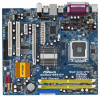
... Core CPU PARALLEL PORT COM1 VGA1 USB2_3 1 27 26 25 24 23 22 21 Top: Line In Center: Line Out Bottom: Mic In Dual Channel Wolfdale1333-DVI USB 2.0 T: USB2 B: USB3 USB 2.0 T: USB0 B: USB1 Top: RJ-45 USB 2.0 T: USB4 B: USB5 USB2.0 Super IO CPU_FAN1 1 IR1... Header (USB2_3, Blue) 10 Red) (IR1) 16 Chassis Speaker Header (SPEAKER 1) 4 CPU Fan Connector (CPU_FAN1) 17 Chassis Fan Connector (CHA_FAN1) 5 775-Pin CPU Socket 18 BIOS SPI Chip 6 North Bridge Controller 19 Floppy Connector (FLOPPY1) 7 2 x 240-pin DDRII DIMM Slots 20 WiFi Header (WIFI) (Dual Channel: DDRII_1,...
... Core CPU PARALLEL PORT COM1 VGA1 USB2_3 1 27 26 25 24 23 22 21 Top: Line In Center: Line Out Bottom: Mic In Dual Channel Wolfdale1333-DVI USB 2.0 T: USB2 B: USB3 USB 2.0 T: USB0 B: USB1 Top: RJ-45 USB 2.0 T: USB4 B: USB5 USB2.0 Super IO CPU_FAN1 1 IR1... Header (USB2_3, Blue) 10 Red) (IR1) 16 Chassis Speaker Header (SPEAKER 1) 4 CPU Fan Connector (CPU_FAN1) 17 Chassis Fan Connector (CHA_FAN1) 5 775-Pin CPU Socket 18 BIOS SPI Chip 6 North Bridge Controller 19 Floppy Connector (FLOPPY1) 7 2 x 240-pin DDRII DIMM Slots 20 WiFi Header (WIFI) (Dual Channel: DDRII_1,...

User Manual
Page 15
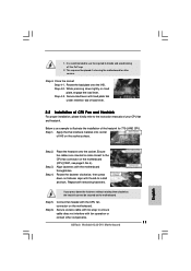
... need to spray thermal interface material between the CPU and the heatsink to improve heat dissipation. Then connect the CPU fan to the CPU_FAN connector (CPU_FAN1, see page 10, No. 4). Step 1. Step 4. Ensure fan cables are securely fastened and in good contact with remaining fasteners...Connect fan header with the motherboard throughholes. Below is equipped with thumb to install and lock. Step 3. Align fasteners with the CPU fan connector on the motherboard. Step 5. Before you installed the heatsink, you press down on the socket surface. Place the heatsink onto the socket....
... need to spray thermal interface material between the CPU and the heatsink to improve heat dissipation. Then connect the CPU fan to the CPU_FAN connector (CPU_FAN1, see page 10, No. 4). Step 1. Step 4. Ensure fan cables are securely fastened and in good contact with remaining fasteners...Connect fan header with the motherboard throughholes. Below is equipped with thumb to install and lock. Step 3. Align fasteners with the CPU fan connector on the motherboard. Step 5. Before you installed the heatsink, you press down on the socket surface. Place the heatsink onto the socket....

User Manual
Page 17
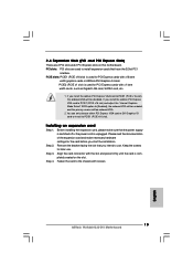
...is unplugged. If you start the installation. You can only choose either PCI Express VGA card or DVI Graphics-SI card to install to the chassis with x16 lane width graphics cards or ASRock DVI Graphics-SI card. PCIE2 (PCIE x1 slot) is used for the card before you install the... add-on this motherboard. Step 3. Installing an expansion card Step 1. Align the card connector with x1 lane width cards, such as Gigabit LAN...
...is unplugged. If you start the installation. You can only choose either PCI Express VGA card or DVI Graphics-SI card to install to the chassis with x16 lane width graphics cards or ASRock DVI Graphics-SI card. PCIE2 (PCIE x1 slot) is used for the card before you install the... add-on this motherboard. Step 3. Installing an expansion card Step 1. Align the card connector with x1 lane width cards, such as Gigabit LAN...

User Manual
Page 18
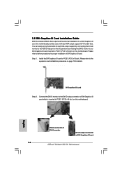
DVI-D connector of DVI-D monitor DVI-D output connector of our DVI Graphics-SI card, this motherboard provides users with dual VGA output support: DVI-D and D-Sub. Please refer to the expansion card installation procedures on this motherboard. Step 1. Install the DVI Graphics-SI card to the DVI-D output connector of DVI Graphics-SI card. 2.7 DVI Graphics-SI Card Installation Guide With the onboard...
DVI-D connector of DVI-D monitor DVI-D output connector of our DVI Graphics-SI card, this motherboard provides users with dual VGA output support: DVI-D and D-Sub. Please refer to the expansion card installation procedures on this motherboard. Step 1. Install the DVI Graphics-SI card to the DVI-D output connector of DVI Graphics-SI card. 2.7 DVI Graphics-SI Card Installation Guide With the onboard...

User Manual
Page 21
...13) SATAII_1 SATAII_2 SATAII_3 SATAII_4 Serial ATA (SATA) Data Cable (Optional) These Serial ATAII (SATAII) connectors support SATAII or SATA hard disk for the details. Then connect the white end of the connector. Serial ATAII Connectors (SATAII_1: see p.10, No. 11) (SATAII_2: see p.10, No. 15) (SATAII_3: see...66/100 cable Note: Please refer to the SATA / SATAII hard disk or the SATAII connector on each drive. 2.9 Onboard Headers and Connectors Onboard headers and connectors are NOT jumpers. FDD connector (33-pin FLOPPY1) (see p.10 No. 19) Pin1 FLOPPY1 the red-striped side to...
...13) SATAII_1 SATAII_2 SATAII_3 SATAII_4 Serial ATA (SATA) Data Cable (Optional) These Serial ATAII (SATAII) connectors support SATAII or SATA hard disk for the details. Then connect the white end of the connector. Serial ATAII Connectors (SATAII_1: see p.10, No. 11) (SATAII_2: see p.10, No. 15) (SATAII_3: see...66/100 cable Note: Please refer to the SATA / SATAII hard disk or the SATAII connector on each drive. 2.9 Onboard Headers and Connectors Onboard headers and connectors are NOT jumpers. FDD connector (33-pin FLOPPY1) (see p.10 No. 19) Pin1 FLOPPY1 the red-striped side to...

User Manual
Page 22
...-802.11n module, an easy-to create a wireless environment and enjoy the convenience of audio devices. The shared USB 2.0 header (USB4_5) is an interface for ASRock DeskExpress. Shared USB 2.0 Header (9-pin USB4_5) (see p.10 No. 27) 1 USB_PWR P-3 P+3 GND USB_PWR P-2 P+2 GND DUMMY WiFi Header (11-pin WIFI) (see...1 GND1 D0-D0+ USB+5V_1 PME# DeskExpress Hot Plug Detection Header IRTX +5VSB Hotplug# (5-pin IR1) (see p.10 No. 3) 1 GND IRRX Internal Audio Connector (4-pin CD1) (CD1: see p.10 No. 23) CD1 CD-L GND GND CD-R Front Panel Audio Header (9-pin HD_AUDIO1) (see p.10 No. 22) GND...
...-802.11n module, an easy-to create a wireless environment and enjoy the convenience of audio devices. The shared USB 2.0 header (USB4_5) is an interface for ASRock DeskExpress. Shared USB 2.0 Header (9-pin USB4_5) (see p.10 No. 27) 1 USB_PWR P-3 P+3 GND USB_PWR P-2 P+2 GND DUMMY WiFi Header (11-pin WIFI) (see...1 GND1 D0-D0+ USB+5V_1 PME# DeskExpress Hot Plug Detection Header IRTX +5VSB Hotplug# (5-pin IR1) (see p.10 No. 3) 1 GND IRRX Internal Audio Connector (4-pin CD1) (CD1: see p.10 No. 23) CD1 CD-L GND GND CD-R Front Panel Audio Header (9-pin HD_AUDIO1) (see p.10 No. 22) GND...

User Manual
Page 23
...change by clicking "OK". System Panel Header (9-pin PANEL1) (see p.10 No. 14) Chassis Speaker Header (4-pin SPEAKER 1) (see p.10 No. 16) Chassis Fan Connector (3-pin CHA_FAN1) (see p.10 No. 4) 4 3 2 1 GND +12V CPU_FAN_SPEED FAN_SPEED_CONTROL Please connect a CPU fan cable to this header. Please follow the instruction ... HDA to Ground (GND). Please connect the chassis speaker to connect them for HD audio panel only. You don't need to this connector and match the black wire to enter Realtek HD Audio Manager. 1. For Windows® 2000 / XP / XP 64-bit OS: Click "...
...change by clicking "OK". System Panel Header (9-pin PANEL1) (see p.10 No. 14) Chassis Speaker Header (4-pin SPEAKER 1) (see p.10 No. 16) Chassis Fan Connector (3-pin CHA_FAN1) (see p.10 No. 4) 4 3 2 1 GND +12V CPU_FAN_SPEED FAN_SPEED_CONTROL Please connect a CPU fan cable to this header. Please follow the instruction ... HDA to Ground (GND). Please connect the chassis speaker to connect them for HD audio panel only. You don't need to this connector and match the black wire to enter Realtek HD Audio Manager. 1. For Windows® 2000 / XP / XP 64-bit OS: Click "...

User Manual
Page 24
... ATX12V1) (see p.10, No. 26) 12 Please connect an ATX power 13 supply to this connector. 1 Though this motherboard, please connect it to Pin 1-3. Though this connector so that it is necessary to connect a power supply with ATX 12V plug to this motherboard provides 4-Pin CPU fan (Quiet Fan...support, the 3-Pin CPU fan still can work if you adopt a traditional 20-pin ATX power supply. Pin 1-3 Connected 3-Pin Fan Installation ATX Power Connector 24 (24-pin ATXPWR1) (see p.10 No. 2) 20-Pin ATX Power Supply Installation 12 1 Please note that it can still work successfully even...
... ATX12V1) (see p.10, No. 26) 12 Please connect an ATX power 13 supply to this connector. 1 Though this motherboard, please connect it to Pin 1-3. Though this connector so that it is necessary to connect a power supply with ATX 12V plug to this motherboard provides 4-Pin CPU fan (Quiet Fan...support, the 3-Pin CPU fan still can work if you adopt a traditional 20-pin ATX power supply. Pin 1-3 Connected 3-Pin Fan Installation ATX Power Connector 24 (24-pin ATXPWR1) (see p.10 No. 2) 20-Pin ATX Power Supply Installation 12 1 Please note that it can still work successfully even...

User Manual
Page 26
STEP 2: Connect the SATA power cable to the motherboard's SATAII connector. Then, the drivers compatible to your system can be auto-detected and listed on this motherboard for the possible overclocking risk before you install can ...
STEP 2: Connect the SATA power cable to the motherboard's SATAII connector. Then, the drivers compatible to your system can be auto-detected and listed on this motherboard for the possible overclocking risk before you install can ...

Quick Installation Guide
Page 2
... DIMM Slots 20 WiFi Header (WIFI) (Dual Channel: DDRII_1, DDRII_2; Red) 25 PCI Express x16 Slot (PCIE1) 12 Third SATAII Connector (SATAII_3; Orange) 27 Shared USB 2.0 Header (USB4_5, Blue) 2 ASRock Wolfdale1333-DVI Motherboard Yellow) 21 PCI Slots (PCI1- 2) 8 IDE1 Connector (IDE1, Blue) 22 Front Panel Audio Header (HD_AUDIO1) 9 Clear CMOS Jumper (CLRCMOS1) 23 AInternal Audio...
... DIMM Slots 20 WiFi Header (WIFI) (Dual Channel: DDRII_1, DDRII_2; Red) 25 PCI Express x16 Slot (PCIE1) 12 Third SATAII Connector (SATAII_3; Orange) 27 Shared USB 2.0 Header (USB4_5, Blue) 2 ASRock Wolfdale1333-DVI Motherboard Yellow) 21 PCI Slots (PCI1- 2) 8 IDE1 Connector (IDE1, Blue) 22 Front Panel Audio Header (HD_AUDIO1) 9 Clear CMOS Jumper (CLRCMOS1) 23 AInternal Audio...

Quick Installation Guide
Page 6
... "Hot Plug" functions) (see CAUTION 12) - 4Mb AMI BIOS - English 6 ASRock Wolfdale1333-DVI Motherboard HD Audio Jack: Line in / Front Speaker / Microphone - 4 x SATAII 3.0 Gb/s connectors (No Support for possible damage caused by overclocking. CPU/Chassis FAN connector - 24 pin ATX power connector - 4 pin 12V power connector - shared with overclocking, including adjusting the setting in header - AMI Legal...
... "Hot Plug" functions) (see CAUTION 12) - 4Mb AMI BIOS - English 6 ASRock Wolfdale1333-DVI Motherboard HD Audio Jack: Line in / Front Speaker / Microphone - 4 x SATAII 3.0 Gb/s connectors (No Support for possible damage caused by overclocking. CPU/Chassis FAN connector - 24 pin ATX power connector - 4 pin 12V power connector - shared with overclocking, including adjusting the setting in header - AMI Legal...

Quick Installation Guide
Page 7
...to read the installation guide of "User Manual" in overclocking mode. Before installing SATAII hard disk to SATAII connector, please read "Untied Overclocking Technology" on page 12 for the CPU FSB frequency and its corre- Power ... information. 10. Although this situation, PCIE frequency will operate in the support CD. 3. mended to SATAII connector directly. 11. Before you install the PC system. 9. Before you implement Dual Channel Memory Technology, make ... power cord, then plug it will automatically shutdown. English 7 ASRock Wolfdale1333-DVI Motherboard
...to read the installation guide of "User Manual" in overclocking mode. Before installing SATAII hard disk to SATAII connector, please read "Untied Overclocking Technology" on page 12 for the CPU FSB frequency and its corre- Power ... information. 10. Although this situation, PCIE frequency will operate in the support CD. 3. mended to SATAII connector directly. 11. Before you install the PC system. 9. Before you implement Dual Channel Memory Technology, make ... power cord, then plug it will automatically shutdown. English 7 ASRock Wolfdale1333-DVI Motherboard
Quick Installation Guide
Page 11
... press down lightly on the socket surface. Step 4. Step 1. Ensure fan cables are oriented on side closest to the CPU fan connector on the motherboard. Step 4-2. Connect fan header with thumb to the instruction manuals of CPU Fan and Heatsink For proper installation, please...cannot be placed if returning the motherboard for 775-LAND CPU. Secure load lever with fan operation or contact other components. 11 ASRock Wolfdale1333-DVI Motherboard English Step 4. Apply thermal interface material onto center of the heatsink for after service. It is an example to handle ...
... press down lightly on the socket surface. Step 4. Step 1. Ensure fan cables are oriented on side closest to the CPU fan connector on the motherboard. Step 4-2. Connect fan header with thumb to the instruction manuals of CPU Fan and Heatsink For proper installation, please...cannot be placed if returning the motherboard for 775-LAND CPU. Secure load lever with fan operation or contact other components. 11 ASRock Wolfdale1333-DVI Motherboard English Step 4. Apply thermal interface material onto center of the heatsink for after service. It is an example to handle ...
Quick Installation Guide
Page 13
... VGA. 2. If you start the installation. Before installing the expansion card, please make necessary hardware settings for PCI Express cards with screws. 13 ASRock Wolfdale1333-DVI Motherboard English Step 3. Step 2. PCIE2 (PCIE x1 slot) is unplugged. PCI slots: PCI slots are 2 PCI slots and 2 PCI Express ... chassis with x1 lane width cards, such as Gigabit LAN card, SATA2 card, etc. 1. Align the card connector with x16 lane width graphics cards or ASRock DVI Graphics-SI card. Please read the documentation of the expansion card and make sure that you install the add-on...
... VGA. 2. If you start the installation. Before installing the expansion card, please make necessary hardware settings for PCI Express cards with screws. 13 ASRock Wolfdale1333-DVI Motherboard English Step 3. Step 2. PCIE2 (PCIE x1 slot) is unplugged. PCI slots: PCI slots are 2 PCI slots and 2 PCI Express ... chassis with x1 lane width cards, such as Gigabit LAN card, SATA2 card, etc. 1. Align the card connector with x16 lane width graphics cards or ASRock DVI Graphics-SI card. Please read the documentation of the expansion card and make sure that you install the add-on...
Quick Installation Guide
Page 14
... DVI-D connector of DVI-D monitor DVI-D output connector of DVI Graphics-SI card. Please refer to below procedures for details. DVI Graphics-SI card Step 2. Connect the DVI-D monitor to the DVI-D output connector of our DVI Graphics-SI card, this motherboard provides users with dual VGA output support: DVI-D... I/O panel and connecting the DVI-D monitor to our DVI Graphics-SI card inserted to the expansion card installation procedures on page 13 for proper installation of DVI Graphics-SI card 14 ASRock Wolfdale1333-DVI Motherboard Install the DVI Graphics-SI card to PCIE1 ...
... DVI-D connector of DVI-D monitor DVI-D output connector of DVI Graphics-SI card. Please refer to below procedures for details. DVI Graphics-SI card Step 2. Connect the DVI-D monitor to the DVI-D output connector of our DVI Graphics-SI card, this motherboard provides users with dual VGA output support: DVI-D... I/O panel and connecting the DVI-D monitor to our DVI Graphics-SI card inserted to the expansion card installation procedures on page 13 for proper installation of DVI Graphics-SI card 14 ASRock Wolfdale1333-DVI Motherboard Install the DVI Graphics-SI card to PCIE1 ...
Quick Installation Guide
Page 15
... function with this motherboard after your computer. English utput connector Graphics-SI card 15 ASRock Wolfdale1333-DVI Motherboard Step 4. Connect the D-Sub monitor to your system and restart your system boots. Then you can freely enjoy the benefits of this motherboard. If ...'t installed Intel® VGA driver yet, please install Intel® VGA driver from our support CD to the VGA/D-Sub port on the I/O panel of DVI-D output function with this motherboard. Step 3.
... function with this motherboard after your computer. English utput connector Graphics-SI card 15 ASRock Wolfdale1333-DVI Motherboard Step 4. Connect the D-Sub monitor to your system and restart your system boots. Then you can freely enjoy the benefits of this motherboard. If ...'t installed Intel® VGA driver yet, please install Intel® VGA driver from our support CD to the VGA/D-Sub port on the I/O panel of DVI-D output function with this motherboard. Step 3.

Quick Installation Guide
Page 17
... Note: Please refer to Pin1 Note: Make sure the red-striped side of the cable is plugged into Pin1 side of the connector. Primary IDE connector (Blue) (39-pin IDE1, see p.2 No. 19) the red-striped side to the instruction of SATA power cable to ... see p.2, No. 13) SATAII_1 SATAII_3 SATAII_4 SATAII_2 Serial ATA (SATA) Data Cable (Optional) These Serial ATAII (SATAII) connectors support SATAII or SATA hard disk for the details. Do NOT place jumper caps over the headers and connectors will cause permanent damage of the power supply. 17 ASRock Wolfdale1333-DVI Motherboard English
... Note: Please refer to Pin1 Note: Make sure the red-striped side of the cable is plugged into Pin1 side of the connector. Primary IDE connector (Blue) (39-pin IDE1, see p.2 No. 19) the red-striped side to the instruction of SATA power cable to ... see p.2, No. 13) SATAII_1 SATAII_3 SATAII_4 SATAII_2 Serial ATA (SATA) Data Cable (Optional) These Serial ATAII (SATAII) connectors support SATAII or SATA hard disk for the details. Do NOT place jumper caps over the headers and connectors will cause permanent damage of the power supply. 17 ASRock Wolfdale1333-DVI Motherboard English
