
User Manual
Page 3
...Expansion Slots (PCI and PCI Express Slots 17 2.7 DVI Graphics-SI Card Installation Guide 18 2.8 Jumpers Setup 20 2.9 Onboard Headers and Connectors 21 2.10 SATAII Hard Disk Setup Guide 25 2.11 Serial ATA (SATA) / Serial ATAII (SATAII) Hard Disks Installation 26 2.12 Driver Installation Guide 26 2.13 Untied Overclocking Technology 26 3 BIOS SETUP UTILITY 27 3.1 Introduction 27 3.1.1 BIOS Menu Bar 27 3.1.2 Navigation Keys 28 3.2 Main Screen 28 3.3 Advanced Screen 28 3.3.1 CPU Configuration 29 3.3.2 Chipset Configuration 31 3.3.3 ACPI Configuration 34 3.3.4 IDE Configuration 35...
...Expansion Slots (PCI and PCI Express Slots 17 2.7 DVI Graphics-SI Card Installation Guide 18 2.8 Jumpers Setup 20 2.9 Onboard Headers and Connectors 21 2.10 SATAII Hard Disk Setup Guide 25 2.11 Serial ATA (SATA) / Serial ATAII (SATAII) Hard Disks Installation 26 2.12 Driver Installation Guide 26 2.13 Untied Overclocking Technology 26 3 BIOS SETUP UTILITY 27 3.1 Introduction 27 3.1.1 BIOS Menu Bar 27 3.1.2 Navigation Keys 28 3.2 Main Screen 28 3.3 Advanced Screen 28 3.3.1 CPU Configuration 29 3.3.2 Chipset Configuration 31 3.3.3 ACPI Configuration 34 3.3.4 IDE Configuration 35...

User Manual
Page 7
...connectors (No Support for possible damage caused by overclocking. 7 CPU Fan Tachometer - Connector BIOS Feature Support CD Hardware Monitor OS Certifications - Front panel audio connector - 1 x USB 2.0 header (supports 2 USB 2.0 ports; Voltage Monitoring: +12V, +5V, +3.3V, Vcore - Microsoft® Windows® 2000 / XP / XP 64-bit / VistaTM / VistaTM 64-bit compliant - It should be done at your system. ACPI 1.1 Compliance Wake Up Events - CPU Temperature Sensing - CPU Quiet Fan - Drivers, Utilities, AntiVirus Software (Trial Version) - We are not responsible for RAID...
...connectors (No Support for possible damage caused by overclocking. 7 CPU Fan Tachometer - Connector BIOS Feature Support CD Hardware Monitor OS Certifications - Front panel audio connector - 1 x USB 2.0 header (supports 2 USB 2.0 ports; Voltage Monitoring: +12V, +5V, +3.3V, Vcore - Microsoft® Windows® 2000 / XP / XP 64-bit / VistaTM / VistaTM 64-bit compliant - It should be done at your system. ACPI 1.1 Compliance Wake Up Events - CPU Temperature Sensing - CPU Quiet Fan - Drivers, Utilities, AntiVirus Software (Trial Version) - We are not responsible for RAID...

User Manual
Page 8
... power cord, then plug it will operate in overclocking mode. CAUTION! 1. Before you resume the system, please check if the CPU fan on page 26 for USB 2.0 works fine under Windows® XP, Windows® XP 64-bit, Windows® VistaTM and Windows® VistaTM 64-bit. 7. Although this motherboard, it back again. mended CPU bus frequencies may be overclocked to perform over-clocking. Before you implement Dual Channel Memory Technology, make sure to change...
... power cord, then plug it will operate in overclocking mode. CAUTION! 1. Before you resume the system, please check if the CPU fan on page 26 for USB 2.0 works fine under Windows® XP, Windows® XP 64-bit, Windows® VistaTM and Windows® VistaTM 64-bit. 7. Although this motherboard, it back again. mended CPU bus frequencies may be overclocked to perform over-clocking. Before you implement Dual Channel Memory Technology, make sure to change...

User Manual
Page 10
...Hot Plug Detection Header (SATAII_2; Orange) 26 ATX Power Connector (ATXPWR1) 13 Fourth SATAII Connector (SATAII_4; Red) (IR1) 16 Chassis Speaker Header (SPEAKER 1) 4 CPU Fan Connector (CPU_FAN1) 17 Chassis Fan Connector (CHA_FAN1) 5 775-Pin CPU Socket 18 BIOS SPI Chip 6 North Bridge Controller 19 Floppy Connector (FLOPPY1) 7 2 x 240-pin DDRII DIMM Slots 20 WiFi Header (WIFI) (Dual Channel: DDRII_1, DDRII_2; Yellow) 21 PCI Slots (PCI1- 2) 8 IDE1 Connector (IDE1, Blue) 22 Front Panel Audio Header (HD_AUDIO1) 9 Clear CMOS Jumper (CLRCMOS1) 23 AInternal Audio Connector...
...Hot Plug Detection Header (SATAII_2; Orange) 26 ATX Power Connector (ATXPWR1) 13 Fourth SATAII Connector (SATAII_4; Red) (IR1) 16 Chassis Speaker Header (SPEAKER 1) 4 CPU Fan Connector (CPU_FAN1) 17 Chassis Fan Connector (CHA_FAN1) 5 775-Pin CPU Socket 18 BIOS SPI Chip 6 North Bridge Controller 19 Floppy Connector (FLOPPY1) 7 2 x 240-pin DDRII DIMM Slots 20 WiFi Header (WIFI) (Dual Channel: DDRII_1, DDRII_2; Yellow) 21 PCI Slots (PCI1- 2) 8 IDE1 Connector (IDE1, Blue) 22 Front Panel Audio Header (HD_AUDIO1) 9 Clear CMOS Jumper (CLRCMOS1) 23 AInternal Audio Connector...

User Manual
Page 25
.../hdd/support/download.htm The above examples are shorted, SATA 1.5Gb/s will be enabled. For different SATAII hard disk products of SATAII hard disks may not be the same. In order to SATAII mode in advance; HITACHI Please use the Feature Tool, a DOS-bootable tool, for the updates. 25 Some default setting of different vendors, the jumper pin setting methods may fail to enable SATAII 3.0Gb/s, please remove the jumpers from pin...
.../hdd/support/download.htm The above examples are shorted, SATA 1.5Gb/s will be enabled. For different SATAII hard disk products of SATAII hard disks may not be the same. In order to SATAII mode in advance; HITACHI Please use the Feature Tool, a DOS-bootable tool, for the updates. 25 Some default setting of different vendors, the jumper pin setting methods may fail to enable SATAII 3.0Gb/s, please remove the jumpers from pin...

User Manual
Page 26
STEP 2: Connect the SATA power cable to fixed PCI / PCIE buses. Therefore, the drivers you enable Untied Overclocking function, please enter "Overclock Mode" option of the SATA data cable to the SATA / SATAII hard disk. 2.12 Driver Installation Guide To install the drivers to your system, please insert the support CD to install those required drivers. STEP 4: Connect the other end of BIOS setup to set the selection from up to bottom side to your system can be auto-detected and listed on...
STEP 2: Connect the SATA power cable to fixed PCI / PCIE buses. Therefore, the drivers you enable Untied Overclocking function, please enter "Overclock Mode" option of the SATA data cable to the SATA / SATAII hard disk. 2.12 Driver Installation Guide To install the drivers to your system, please insert the support CD to install those required drivers. STEP 4: Connect the other end of BIOS setup to set the selection from up to bottom side to your system can be auto-detected and listed on...

User Manual
Page 29
... Use this section may cause system to malfunction. BIOS SETUP UTILITY Main Advanced H/W Monitor Boot Security Exit Advanced Settings WARNING : Setting wrong values in this to select Overclock Mode. The default value is [Auto]. Boot Failure Guard Enable or disable the feature of Boot Failure Guard. CPU Thermal Throttling No-Excute Memory Protection Hyper Threading Technology Intel (R) SpeedStep(tm) tech. [Disabled] [Disabled] [Enabled] [Enabled] [Disabled] [Enabled] [Auto] Select the over clock mode. +F1 F9 F10 ESC Select Screen Select Item Change Option General Help Load...
... Use this section may cause system to malfunction. BIOS SETUP UTILITY Main Advanced H/W Monitor Boot Security Exit Advanced Settings WARNING : Setting wrong values in this to select Overclock Mode. The default value is [Auto]. Boot Failure Guard Enable or disable the feature of Boot Failure Guard. CPU Thermal Throttling No-Excute Memory Protection Hyper Threading Technology Intel (R) SpeedStep(tm) tech. [Disabled] [Disabled] [Enabled] [Enabled] [Disabled] [Enabled] [Auto] Select the over clock mode. +F1 F9 F10 ESC Select Screen Select Item Change Option General Help Load...

User Manual
Page 30
... processor with disable. Ratio Status This is a read -only item, which displays whether the ratio status of this motherboard is "Locked" or "Unlocked". CPU Thermal Throttling You may select [Enabled] to enable P4 CPU internal thermal control mechanism to allow you changing the ratio value of this motherboard. This option will find an item Ratio CMOS Setting appears to keep the CPU from being used by Vanderpool Technology...
... processor with disable. Ratio Status This is a read -only item, which displays whether the ratio status of this motherboard is "Locked" or "Unlocked". CPU Thermal Throttling You may select [Enabled] to enable P4 CPU internal thermal control mechanism to allow you changing the ratio value of this motherboard. This option will find an item Ratio CMOS Setting appears to keep the CPU from being used by Vanderpool Technology...

User Manual
Page 31
... be hidden if the installed CPU does not support Hyper-Threading technology. Processor can switch between multiple frequency and voltage points to Precharge [Auto] Options Auto 200MHz 266MHz 333MHz (DDRII400) (DDRII533) (DDRII667) Primary Graphics Adapter Internal Graphics Mode Select DVMT Mode Select DVMT/FIXED Memory OnBoard HD Audio Front Panel OnBoard Lan PCI Fix Function [PCI] [Auto] [DVMT Mode] [Maximum DVMT] [Auto] [Auto] [Enabled] [Enabled] +F1 F9 F10 ESC Select Screen Select Item Change Option General Help Load Defaults Save and Exit Exit v02.54...
... be hidden if the installed CPU does not support Hyper-Threading technology. Processor can switch between multiple frequency and voltage points to Precharge [Auto] Options Auto 200MHz 266MHz 333MHz (DDRII400) (DDRII533) (DDRII667) Primary Graphics Adapter Internal Graphics Mode Select DVMT Mode Select DVMT/FIXED Memory OnBoard HD Audio Front Panel OnBoard Lan PCI Fix Function [PCI] [Auto] [DVMT Mode] [Maximum DVMT] [Auto] [Auto] [Enabled] [Enabled] +F1 F9 F10 ESC Select Screen Select Item Change Option General Help Load Defaults Save and Exit Exit v02.54...

User Manual
Page 32
... be used under Windows® VistaTM OS because the driver will not be enabled. the onboard VGA will be enabled without the installation of the system memory is available to 128MB, if necessary. Configuration options: [Fixed Mode], [DVMT Mode] and [Fixed+DVMT Mode]. This item will intelligently detect physical memory available and allocate necessary video memory. 32 Configuration options are [6], [5], [4], [3] and [Auto]. Configuration options: [Onboard], [PCI] and [PCI Express]. The default value is issued. In Fixed mode, a fixed-size...
... be used under Windows® VistaTM OS because the driver will not be enabled. the onboard VGA will be enabled without the installation of the system memory is available to 128MB, if necessary. Configuration options: [Fixed Mode], [DVMT Mode] and [Fixed+DVMT Mode]. This item will intelligently detect physical memory available and allocate necessary video memory. 32 Configuration options are [6], [5], [4], [3] and [Auto]. Configuration options: [Onboard], [PCI] and [PCI Express]. The default value is issued. In Fixed mode, a fixed-size...

User Manual
Page 37
... Use this item to enable 32-bit access to keep the default value unless the installed PCI expansion cards' specifications require other settings. S.M.A.R.T. PCI Latency Timer The default value is recommended to maximize the IDE hard disk data transfer rate. 3.3.5 PCIPnP Configuration BIOS SETUP UTILITY Advanced Advanced PCI / PnP Settings PCI Latency Timer PCI IDE BusMaster [32] [Enabled] Value in units of PCI clocks for PCI device latency timer register. +F1 F9 F10 ESC Select Screen Select Item Change Option General Help Load Defaults...
... Use this item to enable 32-bit access to keep the default value unless the installed PCI expansion cards' specifications require other settings. S.M.A.R.T. PCI Latency Timer The default value is recommended to maximize the IDE hard disk data transfer rate. 3.3.5 PCIPnP Configuration BIOS SETUP UTILITY Advanced Advanced PCI / PnP Settings PCI Latency Timer PCI IDE BusMaster [32] [Enabled] Value in units of PCI clocks for PCI device latency timer register. +F1 F9 F10 ESC Select Screen Select Item Change Option General Help Load Defaults...

User Manual
Page 39
... start to enable or disable the use of the parallel port. USB 2.0 Support Use this item to enable or disable the support to enable or disable the USB 2.0 support. Or you may select [Auto] so that the system will show the EPP version in the following item, "EPP Version". Configuration options: [IRQ5] and [IRQ7]. 3.3.8 USB Configuration BIOS SETUP UTILITY Advanced USB Configuration USB Controller USB 2.0 Support Legacy USB Support [Enabled] [Enabled] [Disabled] To enable or disable the onboard USB controllers. +F1 F9 F10 ESC Select Screen Select Item Change Option General Help Load...
... start to enable or disable the use of the parallel port. USB 2.0 Support Use this item to enable or disable the support to enable or disable the USB 2.0 support. Or you may select [Auto] so that the system will show the EPP version in the following item, "EPP Version". Configuration options: [IRQ5] and [IRQ7]. 3.3.8 USB Configuration BIOS SETUP UTILITY Advanced USB Configuration USB Controller USB 2.0 Support Legacy USB Support [Enabled] [Enabled] [Disabled] To enable or disable the onboard USB controllers. +F1 F9 F10 ESC Select Screen Select Item Change Option General Help Load...

User Manual
Page 44
... 4 Software Support 4.1 Install Operating System This motherboard supports various Microsoft® Windows® operating systems: 2000 / XP / XP 64-bit / VistaTM / VistaTM 64-bit. Refer to install it. 4.2.4 Contact Information If you may contact your dealer for more about ASRock, welcome to visit ASRock's website at http://www.asrock.com; Because motherboard settings and hardware options vary, use the setup procedures in the Support CD to activate the devices. 4.2.3 Utilities Menu...
... 4 Software Support 4.1 Install Operating System This motherboard supports various Microsoft® Windows® operating systems: 2000 / XP / XP 64-bit / VistaTM / VistaTM 64-bit. Refer to install it. 4.2.4 Contact Information If you may contact your dealer for more about ASRock, welcome to visit ASRock's website at http://www.asrock.com; Because motherboard settings and hardware options vary, use the setup procedures in the Support CD to activate the devices. 4.2.3 Utilities Menu...

Quick Installation Guide
Page 6
...) - 4Mb AMI BIOS - Voltage Monitoring: +12V, +5V, +3.3V, Vcore - Supports "Plug and Play" - CPU Temperature Sensing - Overclocking may affect your system stability, or even cause damage to the components and devices of your own risk and expense. Microsoft® Windows® 2000 / XP / XP 64-bit / VistaTM / VistaTM 64-bit compliant - English 6 ASRock Wolfdale1333-DVI Motherboard Drivers, Utilities, AntiVirus Software (Trial Version) - Chassis Fan Tachometer - Supports jumperfree - AMI Legal BIOS - HD Audio Jack: Line in...
...) - 4Mb AMI BIOS - Voltage Monitoring: +12V, +5V, +3.3V, Vcore - Supports "Plug and Play" - CPU Temperature Sensing - Overclocking may affect your system stability, or even cause damage to the components and devices of your own risk and expense. Microsoft® Windows® 2000 / XP / XP 64-bit / VistaTM / VistaTM 64-bit compliant - English 6 ASRock Wolfdale1333-DVI Motherboard Drivers, Utilities, AntiVirus Software (Trial Version) - Chassis Fan Tachometer - Supports jumperfree - AMI Legal BIOS - HD Audio Jack: Line in...

Quick Installation Guide
Page 7
..., PCIE frequency will operate in the support CD. 3. This motherboard supports Untied Overclocking Technology. Due to SATAII mode. Although this motherboard, it will automatically shutdown. Power Management for the latest information. 10. Please read the "SATAII Hard Disk Setup Guide" on this motherboard offers stepless control, it back again. mended CPU bus frequencies may be overclocked to change. While CPU overheat is subject to 115MHz. 2. You can also connect SATA hard disk to perform over-clocking. CPU FSB Frequency Memory Support Frequency...
..., PCIE frequency will operate in the support CD. 3. This motherboard supports Untied Overclocking Technology. Due to SATAII mode. Although this motherboard, it will automatically shutdown. Power Management for the latest information. 10. Please read the "SATAII Hard Disk Setup Guide" on this motherboard offers stepless control, it back again. mended CPU bus frequencies may be overclocked to change. While CPU overheat is subject to 115MHz. 2. You can also connect SATA hard disk to perform over-clocking. CPU FSB Frequency Memory Support Frequency...
Quick Installation Guide
Page 14
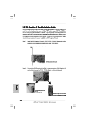
... dual VGA output support by connecting the D-Sub monitor to the VGA/D-Sub port on the I/O panel and connecting the DVI-D monitor to our DVI Graphics-SI card inserted to PCIE1 (PCIE x16 slot) on this motherboard. Install the DVI Graphics-SI card to the expansion card installation procedures on page 13 for proper installation of DVI Graphics-SI card. English DVI-D connector of DVI-D monitor DVI-D output connector of DVI Graphics-SI card 14 ASRock Wolfdale1333-DVI Motherboard Step 1. Please refer to PCIE1 (PCIE x16 slot). 2.5 DVI Graphics-SI Card Installation Guide With the onboard...
... dual VGA output support by connecting the D-Sub monitor to the VGA/D-Sub port on the I/O panel and connecting the DVI-D monitor to our DVI Graphics-SI card inserted to PCIE1 (PCIE x16 slot) on this motherboard. Install the DVI Graphics-SI card to the expansion card installation procedures on page 13 for proper installation of DVI Graphics-SI card. English DVI-D connector of DVI-D monitor DVI-D output connector of DVI Graphics-SI card 14 ASRock Wolfdale1333-DVI Motherboard Step 1. Please refer to PCIE1 (PCIE x16 slot). 2.5 DVI Graphics-SI Card Installation Guide With the onboard...
Quick Installation Guide
Page 15
... monitor to your system and restart your system boots. Step 4. English utput connector Graphics-SI card 15 ASRock Wolfdale1333-DVI Motherboard If you have installed Intel® VGA driver from our support CD to the VGA/D-Sub port on the I/O panel of DVI-D output function with this motherboard. If you haven't installed Intel® VGA driver yet, please install Intel® VGA driver from our support CD to use DVI-D output function with this motherboard. Then you can start...
... monitor to your system and restart your system boots. Step 4. English utput connector Graphics-SI card 15 ASRock Wolfdale1333-DVI Motherboard If you have installed Intel® VGA driver from our support CD to the VGA/D-Sub port on the I/O panel of DVI-D output function with this motherboard. If you haven't installed Intel® VGA driver yet, please install Intel® VGA driver from our support CD to use DVI-D output function with this motherboard. Then you can start...
Quick Installation Guide
Page 19
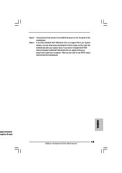
...select "Connector Settings" , choose "Disable front panel jack detection", and save the change by clicking "OK". 1. High Definition Audio supports Jack Sensing, but the panel wire on the lower right hand taskbar to this header. Enter Advanced Settings, and then select Chipset Configuration. Enter Windows system. C. Connect Ground (GND) to connect them for HD audio panel only. You don't need to Ground (GND). Set the Front Panel Control option from [Auto] to the ground pin. 19 ASRock Wolfdale1333-DVI Motherboard English Chassis Speaker Header (4-pin SPEAKER...
...select "Connector Settings" , choose "Disable front panel jack detection", and save the change by clicking "OK". 1. High Definition Audio supports Jack Sensing, but the panel wire on the lower right hand taskbar to this header. Enter Advanced Settings, and then select Chipset Configuration. Enter Windows system. C. Connect Ground (GND) to connect them for HD audio panel only. You don't need to Ground (GND). Set the Front Panel Control option from [Auto] to the ground pin. 19 ASRock Wolfdale1333-DVI Motherboard English Chassis Speaker Header (4-pin SPEAKER...
Quick Installation Guide
Page 22
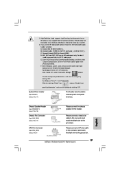
... guide you apply Untied Overclocking Technology. 22 ASRock Wolfdale1333-DVI Motherboard English STEP 2: Connect the SATA power cable to your system can be auto-detected and listed on page 6 for internal storage devices. STEP 4: Connect the other end of your system, please insert the support CD to the SATA / SATAII hard disk. Please follow the order from [Auto] to [CPU, PCIE, Async.]. Please refer to the motherboard's SATAII connector. Before you install can work properly. 2 . 1 1 Untied Overclocking Technology This motherboard supports Untied Overclocking Technology...
... guide you apply Untied Overclocking Technology. 22 ASRock Wolfdale1333-DVI Motherboard English STEP 2: Connect the SATA power cable to your system can be auto-detected and listed on page 6 for internal storage devices. STEP 4: Connect the other end of your system, please insert the support CD to the SATA / SATAII hard disk. Please follow the order from [Auto] to [CPU, PCIE, Async.]. Please refer to the motherboard's SATAII connector. Before you install can work properly. 2 . 1 1 Untied Overclocking Technology This motherboard supports Untied Overclocking Technology...
Quick Installation Guide
Page 23
... to enter BIOS Setup after POST, please restart the system by pressing + + , or pressing the reset button on the file "ASSETUP. Software Support CD information This motherboard supports various Microsoft® Windows® operating systems: 2000 / XP / XP 64-bit / VistaTM / VistaTM 64-bit. otherwise, POST continues with the motherboard contains necessary drivers and useful utilities that will display the Main Menu automatically if "AUTORUN" is enabled in your CD-ROM drive. To begin using the Support...
... to enter BIOS Setup after POST, please restart the system by pressing + + , or pressing the reset button on the file "ASSETUP. Software Support CD information This motherboard supports various Microsoft® Windows® operating systems: 2000 / XP / XP 64-bit / VistaTM / VistaTM 64-bit. otherwise, POST continues with the motherboard contains necessary drivers and useful utilities that will display the Main Menu automatically if "AUTORUN" is enabled in your CD-ROM drive. To begin using the Support...


