User Manual
Page 2
... intent to infringe. This device complies with Part 15 of this motherboard contains Perchlorate, a toxic substance controlled in advance. CALIFORNIA, USA ONLY The Lithium battery adopted on this manual, ASRock does not provide warranty of any interference received, including interference that ...may apply, see www.dtsc.ca.gov/hazardouswaste/perchlorate" ASRock Website: http://www.asrock.com 2 ASRock assumes no event shall ASRock, its directors, officers, employees, or agents be liable for any indirect, special, incidental, or ...
... intent to infringe. This device complies with Part 15 of this motherboard contains Perchlorate, a toxic substance controlled in advance. CALIFORNIA, USA ONLY The Lithium battery adopted on this manual, ASRock does not provide warranty of any interference received, including interference that ...may apply, see www.dtsc.ca.gov/hazardouswaste/perchlorate" ASRock Website: http://www.asrock.com 2 ASRock assumes no event shall ASRock, its directors, officers, employees, or agents be liable for any indirect, special, incidental, or ...

User Manual
Page 3
Contents 1 Introduction 5 1.1 Package Contents 5 1.2 Specifications 6 1.3 Minimum Hardware Requirement Table for Windows® VistaTM Premium 2007 and Basic Logo 9 1.4 Motherboard Layout 10 1.5 ASRock 6CH I/O 11 2 Installation 12 2.1 Screw Holes 12 2.2 Pre-installation Precautions 12 2.3 CPU Installation 13 2.4 Installation of Heatsink and CPU fan 15 2.5 Installation of Memory Modules (...
Contents 1 Introduction 5 1.1 Package Contents 5 1.2 Specifications 6 1.3 Minimum Hardware Requirement Table for Windows® VistaTM Premium 2007 and Basic Logo 9 1.4 Motherboard Layout 10 1.5 ASRock 6CH I/O 11 2 Installation 12 2.1 Screw Holes 12 2.2 Pre-installation Precautions 12 2.3 CPU Installation 13 2.4 Installation of Heatsink and CPU fan 15 2.5 Installation of Memory Modules (...

User Manual
Page 5
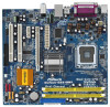
... to change without further notice. www.asrock.com/support/index.asp 1.1 Package Contents ASRock Wolfdale1333-D667 Motherboard (Micro ATX Form Factor: 9.6-in x 8.7-in, 24.4 cm x 22.1 cm) ASRock Wolfdale1333-D667 Quick Installation Guide ASRock Wolfdale1333-D667 Support CD One 80-conductor Ultra ATA 66/100 IDE Ribbon Cable One Ribbon Cable for purchasing ASRock Wolfdale1333-D667 motherboard, a reliable motherboard produced under ASRock's consistently stringent quality control. Chapter...
... to change without further notice. www.asrock.com/support/index.asp 1.1 Package Contents ASRock Wolfdale1333-D667 Motherboard (Micro ATX Form Factor: 9.6-in x 8.7-in, 24.4 cm x 22.1 cm) ASRock Wolfdale1333-D667 Quick Installation Guide ASRock Wolfdale1333-D667 Support CD One 80-conductor Ultra ATA 66/100 IDE Ribbon Cable One Ribbon Cable for purchasing ASRock Wolfdale1333-D667 motherboard, a reliable motherboard produced under ASRock's consistently stringent quality control. Chapter...
User Manual
Page 8
...detected, the system will also be less than the recom- Before installing SATAII hard disk to SATAII mode. This motherboard supports Untied Overclocking Technology. sponding memory support frequency. You can also connect SATA hard disk to spray thermal grease ...modules on this situation, PCIE frequency will automatically shutdown. To improve heat dissipation, remember to SATAII connector directly. 11. Although this motherboard offers stepless control, it back again. mended to 115MHz. 2. Frequencies other than 4GB for the reservation for details. 4. CAUTION...
...detected, the system will also be less than the recom- Before installing SATAII hard disk to SATAII mode. This motherboard supports Untied Overclocking Technology. sponding memory support frequency. You can also connect SATA hard disk to spray thermal grease ...modules on this situation, PCIE frequency will automatically shutdown. To improve heat dissipation, remember to SATAII connector directly. 11. Although this motherboard offers stepless control, it back again. mended to 115MHz. 2. Frequencies other than 4GB for the reservation for details. 4. CAUTION...

User Manual
Page 9
...Requirement Table for Windows® VistaTM Premium 2007 and Basic Logo For system integrators and users who purchase this motherboard, please refer to Premium Discrete requirement at http://www.asrock.com * After June 1, 2007, all Windows® VistaTM systems are required to meet above minimum hardware...Dual Channel (Premium) 512MB Single Channel (Basic) 256MB x 2 Dual Channel (Basic) DX9.0 with ASRock WiFi-802.11g / WiFi-802.11n module, an easy-to-use external graphics card on this motherboard and plan to use wireless local area network (WLAN) adapter. 12. It allows you plan to ...
...Requirement Table for Windows® VistaTM Premium 2007 and Basic Logo For system integrators and users who purchase this motherboard, please refer to Premium Discrete requirement at http://www.asrock.com * After June 1, 2007, all Windows® VistaTM systems are required to meet above minimum hardware...Dual Channel (Premium) 512MB Single Channel (Basic) 256MB x 2 Dual Channel (Basic) DX9.0 with ASRock WiFi-802.11g / WiFi-802.11n module, an easy-to-use external graphics card on this motherboard and plan to use wireless local area network (WLAN) adapter. 12. It allows you plan to ...
User Manual
Page 10
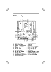
...; 1.4 Motherboard Layout 12 34 56 7 22.1cm (8.7 in) 1 PS2_USB_PWR1 ATX12V1 PS2 Mouse PS2 Keyboard DDRII667 FSB1333 Wolfdale DDRII_2 (64 bit, 240-piFnSmBod8ul0e)0 DDRII_1 (64 bit, 240-piFnSmBod8ul0e)0 Dual Core CPU PARALLEL PORT COM1 VGA1 28 27 26 25 24 23 Top: Line In Center: Line Out Bottom: Mic In Dual Channel Wolfdale1333-D667...
...; 1.4 Motherboard Layout 12 34 56 7 22.1cm (8.7 in) 1 PS2_USB_PWR1 ATX12V1 PS2 Mouse PS2 Keyboard DDRII667 FSB1333 Wolfdale DDRII_2 (64 bit, 240-piFnSmBod8ul0e)0 DDRII_1 (64 bit, 240-piFnSmBod8ul0e)0 Dual Core CPU PARALLEL PORT COM1 VGA1 28 27 26 25 24 23 Top: Line In Center: Line Out Bottom: Mic In Dual Channel Wolfdale1333-D667...

User Manual
Page 12
...Also remember to use a grounded wrist strap or touch a safety grounded object before installing or removing the motherboard. Whenever you handle components. 3. Make sure to the motherboard, peripherals, and/or components. 12 Failure to do so may cause severe damage to unplug the power... place it . Hold components by circles to secure the motherboard to ensure that the power is switched off or the power cord is a Micro ATX form factor (9.6" x 8.7", 24.4 x 22.1 cm) motherboard. Chapter 2 Installation Wolfdale1333-D667 is detached from the wall socket before you and damages ...
...Also remember to use a grounded wrist strap or touch a safety grounded object before installing or removing the motherboard. Whenever you handle components. 3. Make sure to the motherboard, peripherals, and/or components. 12 Failure to do so may cause severe damage to unplug the power... place it . Hold components by circles to secure the motherboard to ensure that the power is switched off or the power cord is a Micro ATX form factor (9.6" x 8.7", 24.4 x 22.1 cm) motherboard. Chapter 2 Installation Wolfdale1333-D667 is detached from the wall socket before you and damages ...

User Manual
Page 14
... the two orientation key notches of the CPU with the two alignment keys of load lever. 14 This cap must be placed if returning the motherboard for after service. Step 4-2. Step 4-3. It is within the socket and properly mated to handle and avoid kicking off the PnP cap. 2. Rotate the load...
... the two orientation key notches of the CPU with the two alignment keys of load lever. 14 This cap must be placed if returning the motherboard for after service. Step 4-2. Step 4-3. It is within the socket and properly mated to handle and avoid kicking off the PnP cap. 2. Rotate the load...
User Manual
Page 15
... CPU to improve heat dissipation. Ensure fan cables are securely fastened and in good contact with the CPU fan connector on the motherboard. Rotate the fastener clockwise, then press down the fasteners without rotating them clockwise, the heatsink cannot be secured on the socket surface...adopt the type of your CPU fan and heatsink. For proper installation, please kindly refer to ensure cable does not interfere with the motherboard throughholes. Step 1. Align fasteners with fan operation or contact other . Secure excess cable with tie-wrap to the instruction manuals of ...
... CPU to improve heat dissipation. Ensure fan cables are securely fastened and in good contact with the CPU fan connector on the motherboard. Rotate the fastener clockwise, then press down the fasteners without rotating them clockwise, the heatsink cannot be secured on the socket surface...adopt the type of your CPU fan and heatsink. For proper installation, please kindly refer to ensure cable does not interfere with the motherboard throughholes. Step 1. Align fasteners with fan operation or contact other . Secure excess cable with tie-wrap to the instruction manuals of ...

User Manual
Page 16
...supply before adding or removing DIMMs or the system components. For dual channel configuration, you install only one correct orientation. otherwise, this motherboard and DIMM may be damaged. 2. Step 1. It will operate at incorrect orientation. If you always need to install two identical (... DIMM on the slot such that the notch on the DIMM matches the break on the slot. 2.5 Installation of Memory Modules (DIMM) Wolfdale1333-D667 motherboard provides two 240-pin DDR2 (Double Data Rate 2) DIMM slots, and supports Dual Channel Memory Technology. Firmly insert the DIMM into DDR2 ...
...supply before adding or removing DIMMs or the system components. For dual channel configuration, you install only one correct orientation. otherwise, this motherboard and DIMM may be damaged. 2. Step 1. It will operate at incorrect orientation. If you always need to install two identical (... DIMM on the slot such that the notch on the DIMM matches the break on the slot. 2.5 Installation of Memory Modules (DIMM) Wolfdale1333-D667 motherboard provides two 240-pin DDR2 (Double Data Rate 2) DIMM slots, and supports Dual Channel Memory Technology. Firmly insert the DIMM into DDR2 ...

User Manual
Page 17
... power supply is switched off or the power cord is used for later use . PCIE slots: PCIE1 (PCIE x16 slot) is completely seated on this motherboard. Step 2. Align the card connector with the slot and press firmly until the card is used for the card before you intend to use . 2.6 Expansion...
... power supply is switched off or the power cord is used for later use . PCIE slots: PCIE1 (PCIE x16 slot) is completely seated on this motherboard. Step 2. Align the card connector with the slot and press firmly until the card is used for the card before you intend to use . 2.6 Expansion...

User Manual
Page 19
... the SATA / SATAII hard disk or the SATAII connector on each drive. Either end of the motherboard! Placing jumper caps over these headers and connectors. The current SATAII interface allows up to the power... PIN1 IDE1 connect the blue end connect the black end to the motherboard to the IDE devices 80-conductor ATA 66/100 cable Note: Please refer to the power connector on... the motherboard. Serial ATAII Connectors (SATAII_1: see p.10, No. 11) (SATAII_2: see p.10, No. 15) ...
... the SATA / SATAII hard disk or the SATAII connector on each drive. Either end of the motherboard! Placing jumper caps over these headers and connectors. The current SATAII interface allows up to the power... PIN1 IDE1 connect the blue end connect the black end to the motherboard to the IDE devices 80-conductor ATA 66/100 cable Note: Please refer to the power connector on... the motherboard. Serial ATAII Connectors (SATAII_1: see p.10, No. 11) (SATAII_2: see p.10, No. 15) ...

User Manual
Page 20
... P-4 P+4 GND DUMMY 1 GND P+5 P-5 USB_PWR 1 GND P-6 P+6 USB_PWR Besides four default USB 2.0 ports on the I/O panel, there are two USB 2.0 headers on this motherboard, this header can support one USB 2.0 port. This connector allows you to use wireless local area network (WLAN) adapter. To connect the 4-Pin USB device...) (see p.10 No. 24) 20 GND PRESENCE# MIC_RET OUT_RET 1 OUT2_L J_SENSE OUT2_R MIC2_R MIC2_L This header supports the Hot Plug detection function for ASRock DeskExpress. WiFi Header (11-pin WIFI) (see p.10 No. 22) USB+5V_2 NC NC GND1 NC+3SVB 1 GND1 D0-D0+ USB+5V_1 PME...
... P-4 P+4 GND DUMMY 1 GND P+5 P-5 USB_PWR 1 GND P-6 P+6 USB_PWR Besides four default USB 2.0 ports on the I/O panel, there are two USB 2.0 headers on this motherboard, this header can support one USB 2.0 port. This connector allows you to use wireless local area network (WLAN) adapter. To connect the 4-Pin USB device...) (see p.10 No. 24) 20 GND PRESENCE# MIC_RET OUT_RET 1 OUT2_L J_SENSE OUT2_R MIC2_R MIC2_L This header supports the Hot Plug detection function for ASRock DeskExpress. WiFi Header (11-pin WIFI) (see p.10 No. 22) USB+5V_2 NC NC GND1 NC+3SVB 1 GND1 D0-D0+ USB+5V_1 PME...

User Manual
Page 22
... 13. 24 13 ATX 12V Connector (4-pin ATX12V1) (see p.10, No. 28) 12 Please connect an ATX power 13 supply to this connector. 1 Though this motherboard provides 24-pin ATX power connector, it can still work successfully even without the fan speed control function. Though this connector so that it is... necessary to connect a power supply with ATX 12V plug to this motherboard provides 4-Pin CPU fan (Quiet Fan) support, the 3-Pin CPU fan still can work if you plan to connect the 3-Pin CPU fan to ...
... 13. 24 13 ATX 12V Connector (4-pin ATX12V1) (see p.10, No. 28) 12 Please connect an ATX power 13 supply to this connector. 1 Though this motherboard provides 24-pin ATX power connector, it can still work successfully even without the fan speed control function. Though this connector so that it is... necessary to connect a power supply with ATX 12V plug to this motherboard provides 4-Pin CPU fan (Quiet Fan) support, the 3-Pin CPU fan still can work if you plan to connect the 3-Pin CPU fan to ...

User Manual
Page 24
.... 24 Please refer to [CPU, PCIE, Async.]. 2 . 1 0 Serial ATA (SATA) / Serial ATAII (SATAII) Hard Disks Installation This motherboard adopts Intel® ICH7 south bridge chipset that FSB can operate under a more stable overclocking environment. STEP 3: Connect one end of BIOS setup to... SATAII hard disk. STEP 2: Connect the SATA power cable to your system can work properly. 2 . 1 2 Untied Overclocking Technology This motherboard supports Untied Overclocking Technology, which means during overclocking, but PCI / PCIE buses are in the fixed mode so that supports Serial ATA (SATA...
.... 24 Please refer to [CPU, PCIE, Async.]. 2 . 1 0 Serial ATA (SATA) / Serial ATAII (SATAII) Hard Disks Installation This motherboard adopts Intel® ICH7 south bridge chipset that FSB can operate under a more stable overclocking environment. STEP 3: Connect one end of BIOS setup to... SATAII hard disk. STEP 2: Connect the SATA power cable to your system can work properly. 2 . 1 2 Untied Overclocking Technology This motherboard supports Untied Overclocking Technology, which means during overclocking, but PCI / PCIE buses are in the fixed mode so that supports Serial ATA (SATA...

User Manual
Page 25
... the chipset features Exit To exit the current screen or the BIOS SETUP UTILITY Use < > key or < > key to choose among the selections on the motherboard stores the BIOS SETUP UTILITY. You may also restart by pressing the reset button on . Because the BIOS software is constantly being updated, the following...
... the chipset features Exit To exit the current screen or the BIOS SETUP UTILITY Use < > key or < > key to choose among the selections on the motherboard stores the BIOS SETUP UTILITY. You may also restart by pressing the reset button on . Because the BIOS software is constantly being updated, the following...
User Manual
Page 28
... mechanism to adjust the ratio value, please disable the option " Intel (R) SpeedStep(tm) tech." Hyper Threading Technology To enable this motherboard. This should be hidden if the current CPU does not support CPU Thermal Throttling. This option will find this..."Locked" or "Unlocked". Ratio CMOS Setting If the ratio status is an enhancement to boot legacy OSes that includes optimization for this motherboard is supported through the native processor instructions HLT and MWAIT and requires no hardware support from being used by Vanderpool Technology. in order to...
... mechanism to adjust the ratio value, please disable the option " Intel (R) SpeedStep(tm) tech." Hyper Threading Technology To enable this motherboard. This should be hidden if the current CPU does not support CPU Thermal Throttling. This option will find this..."Locked" or "Unlocked". Ratio CMOS Setting If the ratio status is an enhancement to boot legacy OSes that includes optimization for this motherboard is supported through the native processor instructions HLT and MWAIT and requires no hardware support from being used by Vanderpool Technology. in order to...

User Manual
Page 29
... memory module(s) inserted and assigns appropriate frequency automatically. Intel (R) SpeedStep(tm) tech. Configuration options: [Auto], [Enabled] and [Disabled]. DRAM Frequency If [Auto] is selected, the motherboard will allow better tolerance for memory compatibility when it is [Disabled]. The configuration options may also select other value as "Portable/Laptop" to enable this...
... memory module(s) inserted and assigns appropriate frequency automatically. Intel (R) SpeedStep(tm) tech. Configuration options: [Auto], [Enabled] and [Disabled]. DRAM Frequency If [Auto] is selected, the motherboard will allow better tolerance for memory compatibility when it is [Disabled]. The configuration options may also select other value as "Portable/Laptop" to enable this...
User Manual
Page 30
.... This item will not be used under Windows® VistaTM OS because the driver will be enabled without the installation of DRAM clocks for the motherboard through efficient memory utilization. Configuration options: [2 DRAM Clocks], [3 DRAM Clocks], [4 DRAM Clocks], [5 DRAM Clocks], [6 DRAM Clocks] and [Auto]. The default value is [PCI]. In DVMT...
.... This item will not be used under Windows® VistaTM OS because the driver will be enabled without the installation of DRAM clocks for the motherboard through efficient memory utilization. Configuration options: [2 DRAM Clocks], [3 DRAM Clocks], [4 DRAM Clocks], [5 DRAM Clocks], [6 DRAM Clocks] and [Auto]. The default value is [PCI]. In DVMT...

User Manual
Page 32
.... ACPI HPET Table Use this item to enable or disable PCI devices to submit Windows® VistaTM certification. 32 PS/2 Keyboard Power On Use this motherboard to turn on the system from the power-soft-off mode. Please set the power state after an unexpected AC/Power loss. Select [Auto] will...
.... ACPI HPET Table Use this item to enable or disable PCI devices to submit Windows® VistaTM certification. 32 PS/2 Keyboard Power On Use this motherboard to turn on the system from the power-soft-off mode. Please set the power state after an unexpected AC/Power loss. Select [Auto] will...

