
User Manual
Page 3
...1.2 Specifications 6 1.3 Minimum Hardware Requirement Table for Windows® VistaTM Premium 2007 and Basic Logo 9 1.4 Motherboard Layout 10 1.5 ASRock 6CH I/O 11 2 Installation 12 2.1 Screw Holes 12 2.2 Pre-installation Precautions 12 2.3 CPU Installation 13 2.4 Installation of Heatsink ... Serial ATAII (SATAII) Hard Disks Installation 24 2.11 Driver Installation Guide 24 2.12 Untied Overclocking Technology 24 3 BIOS SETUP UTILITY 25 3.1 Introduction 25 3.1.1 BIOS Menu Bar 25 3.1.2 Navigation Keys 26 3.2 Main Screen 26 3.3 Advanced Screen 26 3.3.1 CPU Configuration 27 3.3.2 ...
...1.2 Specifications 6 1.3 Minimum Hardware Requirement Table for Windows® VistaTM Premium 2007 and Basic Logo 9 1.4 Motherboard Layout 10 1.5 ASRock 6CH I/O 11 2 Installation 12 2.1 Screw Holes 12 2.2 Pre-installation Precautions 12 2.3 CPU Installation 13 2.4 Installation of Heatsink ... Serial ATAII (SATAII) Hard Disks Installation 24 2.11 Driver Installation Guide 24 2.12 Untied Overclocking Technology 24 3 BIOS SETUP UTILITY 25 3.1 Introduction 25 3.1.1 BIOS Menu Bar 25 3.1.2 Navigation Keys 26 3.2 Main Screen 26 3.3 Advanced Screen 26 3.3.1 CPU Configuration 27 3.3.2 ...

User Manual
Page 5
Chapter 3 and 4 contain the configuration guide to BIOS setup and information of the motherboard and step-bystep guide to change without further notice. You may find the latest VGA cards and CPU support lists on ASRock website without notice. www.asrock.com/support/index.asp 1.1 Package Contents ASRock Wolfdale1333-D667 Motherboard (Micro ATX Form Factor: 9.6-in x 8.7-in...
Chapter 3 and 4 contain the configuration guide to BIOS setup and information of the motherboard and step-bystep guide to change without further notice. You may find the latest VGA cards and CPU support lists on ASRock website without notice. www.asrock.com/support/index.asp 1.1 Package Contents ASRock Wolfdale1333-D667 Motherboard (Micro ATX Form Factor: 9.6-in x 8.7-in...

User Manual
Page 7
... compliant - AMBIOS 2.3.1 Support - CPU Fan Tachometer - It should be done at your system. CD in the BIOS, applying Untied Overclocking Technology, or using the thirdparty overclocking tools. AMI Legal BIOS - ACPI 1.1 Compliance Wake Up Events - Chassis Fan Tachometer - FCC, CE, WHQL WARNING Please realize that there...Chassis Temperature Sensing - We are not responsible for RAID and "Hot Plug" functions) (see CAUTION 12) - 4Mb AMI BIOS - Voltage Monitoring: +12V, +5V, +3.3V, Vcore - CPU/Chassis FAN connector - 24 pin ATX power connector - 4 pin 12V power connector -...
... compliant - AMBIOS 2.3.1 Support - CPU Fan Tachometer - It should be done at your system. CD in the BIOS, applying Untied Overclocking Technology, or using the thirdparty overclocking tools. AMI Legal BIOS - ACPI 1.1 Compliance Wake Up Events - Chassis Fan Tachometer - FCC, CE, WHQL WARNING Please realize that there...Chassis Temperature Sensing - We are not responsible for RAID and "Hot Plug" functions) (see CAUTION 12) - 4Mb AMI BIOS - Voltage Monitoring: +12V, +5V, +3.3V, Vcore - CPU/Chassis FAN connector - 24 pin ATX power connector - 4 pin 12V power connector -...

User Manual
Page 9
...and plan to -use onboard VGA to submit Windows® VistaTM logo, please keep the default setting of "DVMT Mode Select" option under BIOS. * If you to qualify for Windows® VistaTM Premium 2007 and Basic Logo For system integrators and users who purchase this motherboard, please... refer to Premium Discrete requirement at http://www.asrock.com * After June 1, 2007, all Windows® VistaTM systems are required to meet above minimum hardware requirements in order to create a ...
...and plan to -use onboard VGA to submit Windows® VistaTM logo, please keep the default setting of "DVMT Mode Select" option under BIOS. * If you to qualify for Windows® VistaTM Premium 2007 and Basic Logo For system integrators and users who purchase this motherboard, please... refer to Premium Discrete requirement at http://www.asrock.com * After June 1, 2007, all Windows® VistaTM systems are required to meet above minimum hardware requirements in order to create a ...
User Manual
Page 10
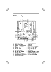
...Fourth SATAII Connector (SATAII_4; Orange) 28 ATX Power Connector (ATXPWR1) 14 System Panel Header (PANEL1) 10 Red) 3 DeskExpress Hot Plug Detection Header 16 BIOS SPI Chip (IR1) 17 Chassis Speaker Header (SPEAKER 1) 4 CPU Fan Connector (CPU_FAN1) 18 Chassis Fan Connector (CHA_FAN1) 5 775-Pin CPU Socket 19...)0 Dual Core CPU PARALLEL PORT COM1 VGA1 28 27 26 25 24 23 Top: Line In Center: Line Out Bottom: Mic In Dual Channel Wolfdale1333-D667 USB 2.0 T: USB2 B: USB3 USB 2.0 T: USB0 B: USB1 Top: RJ-45 Super IO CPU_FAN1 1 IR1 ATXPWR1 Intel 945GC A2 Chipset LAN...
...Fourth SATAII Connector (SATAII_4; Orange) 28 ATX Power Connector (ATXPWR1) 14 System Panel Header (PANEL1) 10 Red) 3 DeskExpress Hot Plug Detection Header 16 BIOS SPI Chip (IR1) 17 Chassis Speaker Header (SPEAKER 1) 4 CPU Fan Connector (CPU_FAN1) 18 Chassis Fan Connector (CHA_FAN1) 5 775-Pin CPU Socket 19...)0 Dual Core CPU PARALLEL PORT COM1 VGA1 28 27 26 25 24 23 Top: Line In Center: Line Out Bottom: Mic In Dual Channel Wolfdale1333-D667 USB 2.0 T: USB2 B: USB3 USB 2.0 T: USB0 B: USB1 Top: RJ-45 Super IO CPU_FAN1 1 IR1 ATXPWR1 Intel 945GC A2 Chipset LAN...

User Manual
Page 17
... with screws. 17 If you install the add-on PCI Express VGA card to PCIE1 (PCIE x16 slot) and adjust the "Internal Graphics Mode Select" BIOS option to install expansion cards that the power supply is switched off or the power cord is used for PCI Express cards with the slot...
... with screws. 17 If you install the add-on PCI Express VGA card to PCIE1 (PCIE x16 slot) and adjust the "Internal Graphics Mode Select" BIOS option to install expansion cards that the power supply is switched off or the power cord is used for PCI Express cards with the slot...

User Manual
Page 21
...) to OUT2_R and Audio_L (LIN) to the front panel audio header as below: A. Enter Advanced Settings, and then select Chipset Configuration. Enter Windows system. 1. D. Enter BIOS Setup Utility. For Windows® VistaTM / VistaTM 64-bit OS: Click the right-top "Folder" icon , choose "Disable front panel jack detection", and save the...
...) to OUT2_R and Audio_L (LIN) to the front panel audio header as below: A. Enter Advanced Settings, and then select Chipset Configuration. Enter Windows system. 1. D. Enter BIOS Setup Utility. For Windows® VistaTM / VistaTM 64-bit OS: Click the right-top "Folder" icon , choose "Disable front panel jack detection", and save the...

User Manual
Page 24
... Serial ATA (SATA) / Serial ATAII (SATAII) hard disks. STEP 2: Connect the SATA power cable to fixed PCI / PCIE buses. STEP 4: Connect the other end of BIOS setup to set the selection from up to bottom side to install those required drivers. Before you to the warning on page 7 for internal storage...
... Serial ATA (SATA) / Serial ATAII (SATAII) hard disks. STEP 2: Connect the SATA power cable to fixed PCI / PCIE buses. STEP 4: Connect the other end of BIOS setup to set the selection from up to bottom side to install those required drivers. Before you to the warning on page 7 for internal storage...

User Manual
Page 25
... top of the screen has a menu bar with its test routines. You may also restart by pressing the reset button on your system. Because the BIOS software is constantly being updated, the following selections: Main To set up the system time/date information Advanced To set up the advanced... BIOS features PCIPnP To set up the PCI features Boot To set up the default system device to locate and load the Operating System Security To ...
... top of the screen has a menu bar with its test routines. You may also restart by pressing the reset button on your system. Because the BIOS software is constantly being updated, the following selections: Main To set up the system time/date information Advanced To set up the advanced... BIOS features PCIPnP To set up the PCI features Boot To set up the default system device to locate and load the Operating System Security To ...

User Manual
Page 26
...the current screen 3.2 Main Screen When you may set the configurations for the following table for all the settings To save changes and exit the BIOS SETUP UTILITY To jump to configure system Time. +Tab F1 F9 F10 ESC Select Screen Select Item Change Field Select Field General Help Load ... UTILITY H/W Monitor Boot System Overview System Time System Date [14:00:09] [Thu 10/25/2007] BIOS Version : Wolfdale1333-D667 P1.00 Processor Type : Intel (R) CPU 3.40 GHz (64bit) Processor Speed : 3400 MHz Microcode Update : F34/17 Cache Size : 1024KB Total Memory DDRII1 DDRII2 : 512MB...
...the current screen 3.2 Main Screen When you may set the configurations for the following table for all the settings To save changes and exit the BIOS SETUP UTILITY To jump to configure system Time. +Tab F1 F9 F10 ESC Select Screen Select Item Change Field Select Field General Help Load ... UTILITY H/W Monitor Boot System Overview System Time System Date [14:00:09] [Thu 10/25/2007] BIOS Version : Wolfdale1333-D667 P1.00 Processor Type : Intel (R) CPU 3.40 GHz (64bit) Processor Speed : 3400 MHz Microcode Update : F34/17 Cache Size : 1024KB Total Memory DDRII1 DDRII2 : 512MB...
User Manual
Page 27
...Frequency (MHz) Use this to select Overclock Mode. Setting wrong values in below sections may cause the system to malfunction. 3.3.1 CPU Configuration BIOS SETUP UTILITY Advanced CPU Configuration Overclock Mode CPU Frequency (MHz) PCIE Frequency (MHz) Boot Failure Guard Spread Spectrum Ratio Actual Value [Auto] ... F1 General Help F9 Load Defaults F10 Save and Exit ESC Exit v02.54 (C) Copyright 1985-2005, American Megatrends, Inc. BIOS SETUP UTILITY Main Advanced H/W Monitor Boot Security Exit Advanced Settings WARNING : Setting wrong values in this section may cause system to...
...Frequency (MHz) Use this to select Overclock Mode. Setting wrong values in below sections may cause the system to malfunction. 3.3.1 CPU Configuration BIOS SETUP UTILITY Advanced CPU Configuration Overclock Mode CPU Frequency (MHz) PCIE Frequency (MHz) Boot Failure Guard Spread Spectrum Ratio Actual Value [Auto] ... F1 General Help F9 Load Defaults F10 Save and Exit ESC Exit v02.54 (C) Copyright 1985-2005, American Megatrends, Inc. BIOS SETUP UTILITY Main Advanced H/W Monitor Boot Security Exit Advanced Settings WARNING : Setting wrong values in this section may cause system to...

User Manual
Page 29
... Defaults Save and Exit Exit v02.54 (C) Copyright 1985-2005, American Megatrends, Inc. Please set this item to [Disable] if above issue occurs. 3.3.2 Chipset Configuration BIOS SETUP UTILITY Advanced Chipset Configuration DRAM Frequency [Auto] Flexibility Option [Disabled] DRAM CAS# Latency [Auto] DRAM RAS# to CAS# Delay [Auto] DRAM RAS# Precharge [Auto...
... Defaults Save and Exit Exit v02.54 (C) Copyright 1985-2005, American Megatrends, Inc. Please set this item to [Disable] if above issue occurs. 3.3.2 Chipset Configuration BIOS SETUP UTILITY Advanced Chipset Configuration DRAM Frequency [Auto] Flexibility Option [Disabled] DRAM CAS# Latency [Auto] DRAM RAS# to CAS# Delay [Auto] DRAM RAS# Precharge [Auto...

User Manual
Page 32
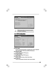
PCI Devices Power On Use this motherboard to submit Windows® VistaTM certification. 32 3.3.3 ACPI Configuration BIOS SETUP UTILITY Advanced ACPI Configuration Suspend To RAM Restore on the system. If [Power Off] is [Disabled]. The default value is selected, the AC/Power ...
PCI Devices Power On Use this motherboard to submit Windows® VistaTM certification. 32 3.3.3 ACPI Configuration BIOS SETUP UTILITY Advanced ACPI Configuration Suspend To RAM Restore on the system. If [Power Off] is [Disabled]. The default value is selected, the AC/Power ...

User Manual
Page 33
... ESC Select Screen Select Item Change Option General Help Load Defaults Save and Exit Exit v02.54 (C) Copyright 1985-2005, American Megatrends, Inc. 3.3.4 IDE Configuration BIOS SETUP UTILITY Advanced IDE Configuration ATA/IDE Configuration SATAII 1 SATAII 2 SATAII 3 SATAII 4 IDE1 Master IDE1 Slave [Enhanced] [Hard Disk] [Not Detected] [Not Detected] [Not Detected...
... ESC Select Screen Select Item Change Option General Help Load Defaults Save and Exit Exit v02.54 (C) Copyright 1985-2005, American Megatrends, Inc. 3.3.4 IDE Configuration BIOS SETUP UTILITY Advanced IDE Configuration ATA/IDE Configuration SATAII 1 SATAII 2 SATAII 3 SATAII 4 IDE1 Master IDE1 Slave [Enhanced] [Hard Disk] [Not Detected] [Not Detected] [Not Detected...

User Manual
Page 34
After selecting the hard disk information into BIOS, use of IDE device. [Auto]: Select [Auto] to the system. +F1 F9 F10 ESC Select Screen Select Item Change Option General Help Load Defaults Save ... IDE ARMD (ATAPI Removable Media Device), such as FDISK, to active. [CD/DVD]: This is used for IDE CD/DVD drives. [ARMD]: This is [Auto]. BIOS SETUP UTILITY Advanced Primary IDE Master Device Vendor Size LBA Mode Block Mode PIO Mode Async DMA Ultra DMA S.M.A.R.T. Make sure to set the PIO...
After selecting the hard disk information into BIOS, use of IDE device. [Auto]: Select [Auto] to the system. +F1 F9 F10 ESC Select Screen Select Item Change Option General Help Load Defaults Save ... IDE ARMD (ATAPI Removable Media Device), such as FDISK, to active. [CD/DVD]: This is used for IDE CD/DVD drives. [ARMD]: This is [Auto]. BIOS SETUP UTILITY Advanced Primary IDE Master Device Vendor Size LBA Mode Block Mode PIO Mode Async DMA Ultra DMA S.M.A.R.T. Make sure to set the PIO...
User Manual
Page 35
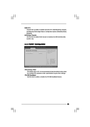
... or disable the PCI IDE BusMaster feature. 35 PCI IDE BusMaster Use this item to maximize the IDE hard disk data transfer rate. 3.3.5 PCIPnP Configuration BIOS SETUP UTILITY Advanced Advanced PCI / PnP Settings PCI Latency Timer PCI IDE BusMaster [32] [Enabled] Value in units of PCI clocks for PCI device latency...
... or disable the PCI IDE BusMaster feature. 35 PCI IDE BusMaster Use this item to maximize the IDE hard disk data transfer rate. 3.3.5 PCIPnP Configuration BIOS SETUP UTILITY Advanced Advanced PCI / PnP Settings PCI Latency Timer PCI IDE BusMaster [32] [Enabled] Value in units of PCI clocks for PCI device latency...
User Manual
Page 36
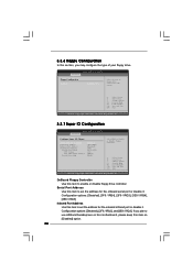
... Help Load Defaults Save and Exit Exit v02.54 (C) Copyright 1985-2005, American Megatrends, Inc. 3.3.7 Super IO Configuration BIOS SETUP UTILITY Advanced Configure Super IO Chipset OnBoard Floppy Controller Serial Port Address Infrared Port Address Parallel Port Address Parallel Port Mode...Option General Help Load Defaults Save and Exit Exit v02.54 (C) Copyright 1985-2005, American Megatrends, Inc. Serial Port Address Use this item to use ASRock DeskExpress on [Disabled] option. 36 Configuration options: [Disabled], [3F8 / IRQ4], [2F8 / IRQ3], [3E8 / IRQ4], [2E8 / IRQ3]. 3.3.6...
... Help Load Defaults Save and Exit Exit v02.54 (C) Copyright 1985-2005, American Megatrends, Inc. 3.3.7 Super IO Configuration BIOS SETUP UTILITY Advanced Configure Super IO Chipset OnBoard Floppy Controller Serial Port Address Infrared Port Address Parallel Port Address Parallel Port Mode...Option General Help Load Defaults Save and Exit Exit v02.54 (C) Copyright 1985-2005, American Megatrends, Inc. Serial Port Address Use this item to use ASRock DeskExpress on [Disabled] option. 36 Configuration options: [Disabled], [3F8 / IRQ4], [2F8 / IRQ3], [3E8 / IRQ4], [2E8 / IRQ3]. 3.3.6...
User Manual
Page 37
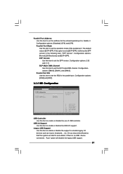
... such as mouse, keyboard,... Configuration options: [Normal], [Bi-Directional], and [ECP+EPP]. Configuration options: [Disabled], [378], and [278]. Configuration options: [IRQ5] and [IRQ7]. 3.3.8 USB Configuration BIOS SETUP UTILITY Advanced USB Configuration USB Controller USB 2.0 Support Legacy USB Support [Enabled] [Enabled] [Disabled] To enable or disable the onboard USB controllers. +F1 F9...
... such as mouse, keyboard,... Configuration options: [Normal], [Bi-Directional], and [ECP+EPP]. Configuration options: [Disabled], [378], and [278]. Configuration options: [IRQ5] and [IRQ7]. 3.3.8 USB Configuration BIOS SETUP UTILITY Advanced USB Configuration USB Controller USB 2.0 Support Legacy USB Support [Enabled] [Enabled] [Disabled] To enable or disable the onboard USB controllers. +F1 F9...

User Manual
Page 38
... will operate in full speed. If you set the target fan speed. You can freely adjust the target fan speed according to allow you choose. BIOS SETUP UTILITY Main Advanced H/W Monitor Boot Security Exit Hardware Health Event Monitoring CPU Temperature M / B Temperature : 37 C / 98 F : 31 C / 87 F Target Fan Speed Fast Middle Slow...
... will operate in full speed. If you set the target fan speed. You can freely adjust the target fan speed according to allow you choose. BIOS SETUP UTILITY Main Advanced H/W Monitor Boot Security Exit Hardware Health Event Monitoring CPU Temperature M / B Temperature : 37 C / 98 F : 31 C / 87 F Target Fan Speed Fast Middle Slow...

User Manual
Page 39
...Help F9 Load Defaults F10 Save and Exit ESC Exit v02.54 (C) Copyright 1985-2005, American Megatrends, Inc. 3.5.1 Boot Settings Configuration BIOS SETUP UTILITY Boot Boot Settings Configuration Boot From Onboard LAN Bootup Num-Lock [Disabled] [On] To enable or disable the boot from ... ROM C] [USB] Select Screen Select Item Enter Go to enable or disable the Boot From Onboard LAN feature. CD - Main Advanced BIOS SETUP UTILITY H/W Monitor Boot Security Exit Boot Settings Boot Settings Configuration Configure Settings during System Boot. 1st Boot Device 2nd Boot Device 3rd ...
...Help F9 Load Defaults F10 Save and Exit ESC Exit v02.54 (C) Copyright 1985-2005, American Megatrends, Inc. 3.5.1 Boot Settings Configuration BIOS SETUP UTILITY Boot Boot Settings Configuration Boot From Onboard LAN Bootup Num-Lock [Disabled] [On] To enable or disable the boot from ... ROM C] [USB] Select Screen Select Item Enter Go to enable or disable the Boot From Onboard LAN feature. CD - Main Advanced BIOS SETUP UTILITY H/W Monitor Boot Security Exit Boot Settings Boot Settings Configuration Configure Settings during System Boot. 1st Boot Device 2nd Boot Device 3rd ...


